DESIGN OF A WIDEBAND ARTIFICIAL MAGNETIC CONDUCTOR ...
DESIGN OF A WIDEBAND ARTIFICIAL MAGNETIC CONDUCTOR ...
DESIGN OF A WIDEBAND ARTIFICIAL MAGNETIC CONDUCTOR ...

Create successful ePaper yourself
Turn your PDF publications into a flip-book with our unique Google optimized e-Paper software.
J. of Electromagn. Waves and Appl., Vol. 22, 2125–2134, 2008<strong>DESIGN</strong> <strong>OF</strong> A <strong>WIDEBAND</strong> <strong>ARTIFICIAL</strong> <strong>MAGNETIC</strong><strong>CONDUCTOR</strong> (AMC) GROUND PLANE FORLOW-PR<strong>OF</strong>ILE ANTENNASJ. YeoSchool of Computer & Communication EngineeringDaegu UniversityGyeongbuk 712-714, KoreaD. KimElectromagnetic Future Technology Research TeamElectronics and Telecommunications Research InstituteDaejeon 305-700, KoreaAbstract—A novel low-profile wideband dipole antenna on a taperedartificial magnetic conductor (AMC) ground plane is proposed. Atapered AMC ground plane consisting of strip dipoles with differentlengths is designed to increase the bandwidth of a dipole antennaplaced right above it. The lowest frequency, where the destructiveinterference becomes dominant and the main beam in broadsidedirection starts to split, can also be increased with the proposedtapered AMC ground plane. Consequently, the 3 dB bandwidth of therealized gain of the proposed antenna with a modified tapered AMCground plane is almost twice wider compared to that with a uniformAMC ground plane.1. INTRODUCTIONIt is well-known that if a horizontally-polarized antenna is placed closeto a perfect electric conductor (PEC), the radiation efficiency of theantenna becomes poor because the image currents cancel out thoseon the antenna [1]. To overcome this problem, a perfect magneticconductor (PMC), which doesn’t exist in nature, can be used.Recently, artificial magnetic conductor (AMC) structures havebeen used to mimic a PMC ground plane over a limited narrowfrequency range, which show in-phase reflection behavior at a certainfrequency band [2]. AMC has been realized either by employing a2D periodic metallic array or by using a periodic array of dielectricinclusions whose parameters are different from those of the host
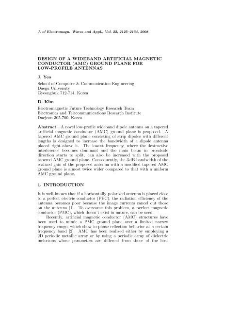
2126 Yeo and Kimmaterial. Extension of a high-impedance bandwidth, compactness of aunit cell, and the angular sensitivity have been main research issues onAMCs [3–5]. Microstrip patch antennas or dipole antennas have beenused as a horizontal antenna, and several methods have been triedto enhance the overall performance of the antenna [6, 7]. An ultrawidebandAMC has been realized by loading the elements of EBGstructures with active devices, which are known as Negative ImpedanceConverters (NICs) [8].Characteristics of a non-periodic AMC with patches of differentlengths and the performance of a high-gain wideband low-profileantenna by using a double-dipole located above that kinds of AMCshave been investigated in [9, 10], respectively. It has been found thatthe main lobe at broadside direction tends to split into several beamsbeyond the resonant frequency of a uniform AMC consisting of regularperiodic patches. This phenomenon has been analyzed by studying thesurface currents on the patches of the AMC. With a uniform AMC,the surface currents induced along successive patches perpendicular tothe antenna have shown a phase shift close to 180 ◦ , which generatesdestructive interference at broadside direction and splits the radiationpattern. This can be avoided by reducing the rows of patches alongthe direction perpendicular to the antenna. To further improve thedirectivity and increase the bandwidth, the lengths of the patcheshave been gradually decreased from the center of the AMC along thedirection of the antenna. This, however, breaks the periodicity of theoriginal AMC structure and the analysis of the modified structure isnot easy. Recently, broadband dipole antennas such as a diamonddipole or an open sleeve dipole have been used above EBG structuresto achieve a broad bandwidth [11].In this paper, a novel wideband AMC ground plane consistingof strip dipoles with different lengths is proposed to increase thebandwidth of a low-profile antenna. The lengths of the strip dipolesare tapered in both directions on an azimuthal plane keeping theperiodicities of an original uniform AMC. The effect of tapering thelengths of the strip dipoles on the realized gain of the antenna isinvestigated. The 3 dB bandwidth of the realized gain and the radiationpatterns are compared with those of the uniform AMC ground planefor the validation of the proposed AMC one. All simulation data areobtained using CST Microwave Studio (MWS).2. <strong>WIDEBAND</strong> AMC <strong>DESIGN</strong> AND RESULTSFigures 1 and 2 show the geometry of original uniform and taperedAMCs on a grounded substrate. Both AMC ground planes are
a 1nFundamental arra yWideband artificial magnetic conductor (AMC) ground plane 2127yN xth2 nd1 st1 st2 nd N xthN yth2 nd1 st1 st2 ndxg xbp yg yN ythap xunitcellFundamental arrayFigure 1. Geometry of an original uniform AMC on a groundedsubstrate. (a = 8 mm, b = 1 mm, p x = 10 mm, α x = α y =0,Nx =5,and Ny = 11).yN xth2 nd1 st1 st2 nd N xthN ytha 11 a 11a n1 a 21a n1a 21a 11a 11a 122 nd1 st1 st2 ndxa 13bg yN ythFigure 2. Geometry of a tapered AMC on a grounded substrate.(a 11 = 8 mm, b = 1 mm, Nx = 5, and Ny = 11).
2128 Yeo and Kimcomposed of 2Nx×2Ny strip dipoles, and the periodicities of a unit cellin x-and y-directions are fixed as p x and p y , respectively. The wholestructure of the AMC ground planes in Figs. 1 and 2 can be built fromthe mirrored copies of the fundamental array in x-and y-directions,which is depicted as a broken-lined box consisting of Nx×Ny cells. Forthe tapered AMC, a ij indicates the length of the strip dipole of (ith,jth) element in the fundamental array matrix, which is determined bya ij = a 11 · s xi · s yi(= a 11 1 − (i − 1)α )(x1 − (j − 1)α )ya 11 a 11(1)where s xi(yi) and α x(y) are the scaling factors and coefficients in x-(y-)direction, which control the lengths of strip dipoles on the taperedAMC ground plane. The geometry of a dipole antenna located abovean AMC ground plane is shown in Fig. 3. The length and the width ofthe antenna are 17.5 mm and 1 mm, respectively, and it is placed 3 mmabove the AMC ground plane.hdipoleantennazlddAMC patchdielectric substrate ( r )groundxFigure 3. Geometry of a dipole antenna located above an AMCground plane. (d = 3 mm, h = 2 mm, l d =17.5 mm, and ɛ r =3.5).As mentioned earlier, the large phase differences among inducedsurface currents on the strip dipoles perpendicular to the dipoleantenna cause destructive interference at broadside direction, and splitthe main beam into several beams steered toward the end-fire directionnear and beyond the resonant frequency of a uniform AMC. Thisdestructive interference can be avoided if the number of the stripdipoles perpendicular to the antenna decreases or the gap betweenthe dipoles increases.For this purpose, we first investigate the variations of the returnloss and the realized gain of the antenna over an original uniform AMCfor different periodicities in y-direction (p y ), which is the directionperpendicular to the axis of the dipole antenna in the given problemgeometry. In this case, y-direction periodicity p y increases from 3 mmto 5 mm and other dimensional parameters of the AMC are fixed.
Wideband artificial magnetic conductor (AMC) ground plane 2129The return loss and the realized gain of the antenna are plotted inFig. 4. In both cases, the return losses and the gains start to drop andfluctuate from the frequencies of the zero reflection phases. Note thatthe frequencies of zero reflection phase for p y = 3 mm, 4 mm, and 5 mmare 7.9 GHz, 8.3 GHz, and 8.6 GHz, respectively. And, it is observedthat the impedance bandwidth is somewhat similar for three cases,but the bandwidth of the realized gain at broadside increases as they-direction periodicity p y increases. This can be explained by the factthat the longer p y can more effectively reduce the phase differencesamong the surface currents induced on the strip dipoles in y-direction;therefore, it reduces the destructive interference at broadside.(a)Figure 4. Return losses and realized gains (at φ = θ = 0) of theantenna over the original uniform AMC ground plane (α x = α y = 0) fordifferent periodicities in y-direction (p y ), (a) Return loss, (b) Realizedgain. Parameters are the same as those used in Figs. 1 and 3.Next, the tapering effect on the realized gain of the antenna whenthe lengths of the strip dipoles in the uniform AMC ground planeare tapered in y-direction is studied. In this case, y-direction scalingcoefficient α y and periodicity p y are varied. Figure 5(a) shows thereturn loss and the realized gain responses of the antenna for differenty-direction periodicity p y with α y =0.75. We see that the bandwidthof the realized gain increases slightly as p y increases. However,the realized gain bandwidths for y-direction tapered AMC cases arebroader than those for the original uniform AMC with increased y-direction periodicity. Tapering effects of strip dipoles on the realizedgain for different y-direction scaling coefficient α y with p y = 3 mm areplotted in Fig. 5(b). The bandwidth of the realized gain increases asthe y-direction scaling coefficient α y increases. This is mainly becauseof the phase property of the wave reflected by each strip dipole, which(b)
2130 Yeo and Kim(a)Figure 5. Realized gain (φ = θ = 0) of the antenna for the y-direction tapered AMC ground plane for (a) a fixed scaling coefficient ofα y =0.75 (p x = 10 mm), and (b) a fixed periodicity of p y = 3 mm. S 11dand G rd mean the return loss and the realized gain of the same dipoleantenna used in Fig. 5 without the AMC ground plane, respectively.(b)yields larger reflection phase value for a shorter strip. Therefore, theAMC with shorter patches results in phase compensation comparedto that with the longer patches, which effectively restricts the wholephase difference among successive strip dipoles within a certain valuemuch smaller than 180 ◦ .In both cases, the return losses are a little larger than −10 dB over7.6 GHz, but the realized gain is much higher that that of the samedipole antenna used in this paper without the AMC ground plane. Weintentionally used the term realized gain, where all antenna parametersare already considered including the impedance bandwidth behaviorshown in Fig. 5. Therefore, it can be said that the proposed antennais quite efficient from the gain and the bandwidth point of views.The characteristics of the realized gain of the antenna for 4different AMC ground planes, which are uniform, x-direction tapered,y-direction tapered, and xy-direction tapered, are compared in Fig. 6.In all cases, the y-direction periodicity p y is fixed as 5 mm. Among thefour cases, the xy-direction tapered AMC ground plane increases therealized gain bandwidth most widely, which is about twice of the gainbandwidth with the uniform AMC. We also see that the y-directiontapered AMC works better compared to the x-directed AMC becausethe dipole is placed along x-direction. The radiation patterns for theuniform, the y-direction tapered, and the xy-direction tapered AMCsat 7 GHz for E-and H-planes are compared in Figs. 7(a) and (b),respectively. The patterns for the y-direction tapered and the xydirectiontapered AMC look very similar and the side lobe levels are
Wideband artificial magnetic conductor (AMC) ground plane 2131Figure 6. Comparison of the realized gain (φ = θ = 0) for fourdifferent types of AMC ground planes: Uniform AMC, x-directiontapered AMC (α x =1.6), y-direction tapered AMC (α y =0.75), andxy-direction tapered AMC (α x =1.2, α y =0.75). Parameters used inFigs. 1, 2, and 3 are chosen for the appropriate types of AMC groundplanes.(a)(b)Figure 7. Radiation patterns for the uniform, the y-direction tapered(α y =0.75), and the xy-direction tapered (α x =1.2, α y =0.75) AMCground planes at 7 GHz (p y = 3 mm): (a) E-plane and (b) H-plane.very low compared to those for the original uniform AMC case.Figure 8 shows the comparison of the two dimensional normalizedradiation patterns scanned in both θ-and φ-directions at 9 GHz, whichis the frequency where the uniform, the x-direction tapered, and they-direction tapered AMC cases produce the main beam at off thebroadside direction and the reduced broadside realized gain except thexy-direction tapered AMC case. For the uniform AMC case, 6 mainbeams off the broadside direction appear, while two off-broadside main
2132 Yeo and Kim(a)(b)(c)(d)Figure 8. Comparison of the two dimensional normalized radiationpatterns scanned in both θ-and φ-directions at 9 GHz (p y = 3 mm):(a) uniform AMC (α x = α y = 0), (b) x-direction tapered (α x =1.6)AMC, (c) y-direction tapered (α y =0.75) AMC, and (d) xy-directiontapered (α x =1.2, α y =0.75) AMC.beams exist with the x-or y-tapered AMCs. However, one main beamappears in the direction of the broadside for the xy-direction taperedAMC case. In fact, the total number of main beams is a measure ofdestructive interference intensity. Therefore, it can be said that theuniform AMC ground plane operates at the farthest frequency fromthe on-broadside radiation frequency region. In addition, we can findanother interesting phenomenon from Fig. 8. In case of y-directiontapered AMC, the main beams split into the x-direction only, whichcorresponds to φ = 0 in Fig. 8(c). It is because the tapering is appliedonly in y-direction, and the overall phase change in x-direction exceeds180 ◦ . For that reason, the total reflected wave destructively interferedin x-direction splits the main beam as a fashion shown in Fig. 8(c). Thesame can be found in x-direction tapered AMC as shown in Fig. 8(b).Finally, 3 dB bandwidths of the realized gain of the antenna for 4different AMC ground planes are compared for p y = 3 and 5 mm, andthe results are summarized in Table 1. The 3 dB bandwidth increasesfrom 17.8% for the original uniform AMC to 43.8% for the xy-direction
Wideband artificial magnetic conductor (AMC) ground plane 2133Table 1. Comparison of the 3 dB bandwidths of the realized gain ofthe antenna for four different AMC ground planes (p y = 3 mm and5 mm).p y =3mmp y =5mmItems3 dB B.W.3 dB B.W.3 dB band3 dB band(% B.W.) (% B.W.)uniform 6.05 ∼ 7.23 1.18 (17.8%) 6.20 ∼ 8.16 1.96 (27.3%)x-tapererd 6.02 ∼ 7.34 1.32 (19.7%) 6.18 ∼ 8.35 2.17 (29.9%)y-tapered 6.03 ∼ 8.52 2.49 (34.2%) 6.11 ∼ 8.80 2.69 (36.1%)xy-tapered 6.02 ∼ 9.39 3.37 (43.8%) 6.10 ∼ 10.04 3.94 (48.9%)tapered one when y-direction periodicity p y = 3 mm. For p y = 5 mm,the bandwidth increases from 27.3% (the original AMC) to 48.9%(the xy-direction tapered AMC). It is important to note that simpletapering on the strip dipole lengths can largely widen the bandwidthof the realized gain without any sacrifice of the gain itself.3. CONCLUSIONSWe have proposed a novel low-profile (≈ 0.11λ) wideband dipoleantenna on a tapered artificial magnetic conductor (AMC) groundplane. The proposed wideband AMC ground plane is comprised ofstrip dipoles, which are tapered both in lateral directions withoutbreaking the periodicity of an original uniform AMC. It has beenfound that the bandwidth of the realized gain of the antenna can belargely increased by tapering the strip dipole and by increasing theperiodicity of the AMC. The 3 dB bandwidth of the realized gain ofthe proposed antenna with a xy-direction tapered AMC ground planecan be expanded almost twice wider compared to the dipole antennawith the original AMC ground plane.ACKNOWLEDGMENTThis research was supported by the Daegu University Research Grant.REFERENCES1. Sievenpiper, D., L. Zhang, R. Broas, N. G. Alexopolous, andE. Yablonovitch, “High-impedance electromagnetic surfaces witha forbidden frequency band,” IEEE Trans. Microw. Theory Tech.,Vol. 47, No. 11, 2059–2074, 1999.
2134 Yeo and Kim2. Yang, F. and Y. Rahmat-Samii, “Reflection phase characterizationsof the EBG ground plane for low profile wire antenna applications,”IEEE Trans. Antennas Propag., Vol. 51, No. 10, 2691–2703, 2003.3. Akhoondzadeh-Asl, L., J. Nourinia, C. Ghobadi, and P. S. Hall,“Influence of element shape on the bandwidth of artificialmagnetic conductors,” J. of Electromagn. Waves and Appl.,Vol. 21, No. 7, 929–946, 2007.4. Kim, Y., F. Yang, and A. Z. Elsherbeni, “Compact artificial magneticconductor designs using planar square spiral geometries,”Progress In Electromagnetics Research, PIER 77, 43–54, 2007.5. Hosseini, N., A. Pirhadi, and M. Hakkak, “A novel AMC withlittle sensitivity to the angle of incidence using 2-layer Jerusalemcross FSS,” Progress In Electromagnetics Research, PIER 64, 43–51, 2006.6. Yang, F., V. Demir, D. A. Elsherbeni, A. Z. Elsherbeni,and A. A. Eldek, “Enhancement of printed dipole antennascharacteristics using semi-EBG ground plane,” J. of Electromagn.Waves and Appl., Vol. 20, No. 8, 993–1006, 2006.7. Sohn, J. R., K. Y. Kim, H. -S. Tae, and H. J. Lee, “Comparativestudy on various artficial magnetic conductors for low-profileantenna,” Progress In Electromagnetics Research, PIER 61, 27–37, 2006.8. Kern, D. J., D. H. Werner, and M. J. Wilhelm, “Active negativeimpedance loaded EBG structures for the realization of ultrawidebandartificial magnetic conductors,” IEEE Antennas andPropag. Soc. Int. Symp., Vol. 2, 427–430, 2003.9. Fu, Y. Q. and N. C. Yuan, “Reflection phase and frequencybandgap characteristics of EBG structures with anisotropicperiodicity,” J. of Electromagn. Waves and Appl., Vol. 19, No. 14,1897–1905, 2005.10. Mateos, R. M., C. Craeye, and G. Toso, “High-gain widebandlow-profile antenna,” Microwave Opt. Tech. Lett., Vol. 48, No. 12,2615–2619, 2006.11. Akhoondzadeh-Asl, L., D. J. Kern, P. S. Hall, and D. H. Werner,“Wideband dipoles on electromagnetic bandgap ground planes,”IEEE Trans. Antennas Propag., Vol. 55, No. 9, 2426–2434, 2007.