Brake-Link Bendix & Eaton ABS Applications Operator's Manual
Brake-Link Bendix & Eaton ABS Applications Operator's Manual
Brake-Link Bendix & Eaton ABS Applications Operator's Manual

Create successful ePaper yourself
Turn your PDF publications into a flip-book with our unique Google optimized e-Paper software.
NEXIQ <strong>Brake</strong>-<strong>Link</strong><strong>Bendix</strong> ® & <strong>Eaton</strong> ®<strong>ABS</strong> <strong>Applications</strong>Operator’s <strong>Manual</strong>
NEXIQ <strong>Brake</strong>-<strong>Link</strong> <strong>Bendix</strong> ® & <strong>Eaton</strong> ® <strong>ABS</strong> <strong>Applications</strong> Operator’s <strong>Manual</strong>IDSC Holdings LLC retains all ownership rights to <strong>Bendix</strong> ® & Ea ton ® <strong>Applications</strong> and its documentation. The<strong>Bendix</strong> ® & <strong>Eaton</strong> ® <strong>Applications</strong> source code is a confidential trade secret of IDSC Holdings LLC. You may notdecipher or de-compile <strong>Bendix</strong> ® & <strong>Eaton</strong> ® <strong>Applications</strong>, develop source code for <strong>Bendix</strong> ® & <strong>Eaton</strong> ® <strong>Applications</strong>,or knowingly allow others to do so. <strong>Bendix</strong> ® & <strong>Eaton</strong> ® <strong>Applications</strong> and its documentation may not be sublicensedor transferred without the prior written consent of IDSC Holdings LLC.This manual, as w ell as t he so ftware it describes, is furnished und er l icense a nd m ay on ly be us ed or copied i naccordance w ith the terms of such license. The content of this m anual is furnished for informational use only, issubject to change without notice, and should not be construed as a commitment by IDSC Holdings LLC. IDSCHoldings LLC assumes no responsibility or liability for any errors or inaccuracies that may appear in this book.Except as permitted by such license, no part of this publication may be reproduced, or transmitted, in any form or byany means, electronic, mechanical, or otherwise, without the prior written permission of IDSC Holdings LLC.<strong>Bendix</strong> ® is a registered trademark of <strong>Bendix</strong> Commercial Vehicle Systems, LLC.<strong>Eaton</strong> ® is a registered trademark of <strong>Eaton</strong> Corporation.Roadranger ® is a combined registered trademark of <strong>Eaton</strong> ® Corporation and Dana ® Corporation.<strong>Brake</strong>-<strong>Link</strong> and NEXIQ are trademarks of NEXIQ Technologies.©2002−2009 IDSC Holdings LLC. All Rights Reserved.www.nexiq.comPart No. 192149B Revised 01/06/2009
Getting Started ..................................................... 1Getting Started .............................................................................. 2Safety Warnings & Cautions................................................................. 3Using this <strong>Manual</strong>.......................................................................... 4Specialized Text ................................................................................... 4Navigation Icons ................................................................................... 5General Icons ....................................................................................... 5Navigating <strong>Brake</strong>-<strong>Link</strong>................................................................ 6Home Button......................................................................................... 6Enter Button.......................................................................................... 6Menu Buttons........................................................................................ 7Direct Access Buttons........................................................................... 8Light Emitting Diodes (LEDs).............................................................. 13NEXIQ <strong>Brake</strong>-<strong>Link</strong> <strong>Bendix</strong> ® & <strong>Eaton</strong> ® <strong>ABS</strong> <strong>Applications</strong>i
Establishing Connection ....................................... 15Connecting <strong>Brake</strong>-<strong>Link</strong> Components ....................................... 16Selecting a Protocol & Registering the ECU ............................... 19Enabling Enhanced PLC Mode ................................................... 30Diagnosing EC-17, EC-30 & EC-30T <strong>ABS</strong> ............... 33Using EC-17, EC-30 & EC-30T Diagnostic Options.................... 34Current Faults..................................................................................... 34Viewing & Clearing All Active Fault Codes...................................... 35Fault History ....................................................................................... 38Viewing & Clearing All Inactive Fault Codes ................................... 38Data List ............................................................................................. 40Tests................................................................................................... 44Chuffing Modulators ........................................................................ 44Testing Sensor Sequence............................................................... 47Testing Trailer on PLC .................................................................... 49Disabling Traction ........................................................................... 50Running Special Test ...................................................................... 51ECU Information................................................................................. 63Reset ECU ......................................................................................... 65Configuration ...................................................................................... 66Using Self-Configuration ................................................................. 66Modifying System Configuration ..................................................... 68iiNEXIQ <strong>Brake</strong>-<strong>Link</strong> <strong>Bendix</strong> ® & <strong>Eaton</strong> ® <strong>ABS</strong> <strong>Applications</strong>
Diagnosing Gen 4 & 5 <strong>ABS</strong>................................... 71Using the Gen 4 & 5 Diagnostic Options ..................................... 72ECU Information................................................................................. 72Faults.................................................................................................. 74Viewing Existing Faults ................................................................... 75Viewing Stored Faults ..................................................................... 77Clearing Faults ................................................................................ 80Data List ............................................................................................. 83Tests................................................................................................... 85Testing Valves................................................................................. 85Testing Warning Lamp .................................................................... 86Self-Configuration............................................................................... 87EC-17, EC-30 & EC-30T SID/FMI Tables................ 89EC-17 SIDs & FMIs ..................................................................... 90EC-30 SIDs & FMIs ..................................................................... 92EC-30T SIDs & FMIs ................................................................... 95Gen 4 & 5 Fault Code Tables ................................ 97Generation 4................................................................................ 98Generation 5.............................................................................. 100NEXIQ <strong>Brake</strong>-<strong>Link</strong> <strong>Bendix</strong> ® & <strong>Eaton</strong> ® <strong>ABS</strong> <strong>Applications</strong>iii
ivNEXIQ <strong>Brake</strong>-<strong>Link</strong> <strong>Bendix</strong> ® & <strong>Eaton</strong> ® <strong>ABS</strong> <strong>Applications</strong>
1Getting StartedGetting Started, page 2uSafety Warnings & Cautions, page 3uuuUsing this <strong>Manual</strong>, page 4Navigating <strong>Brake</strong>-<strong>Link</strong>, page 6<strong>Brake</strong>-<strong>Link</strong> is a hand-held diagnostic tool primarily designed to troubleshoot heavydutyvehicle Anti-lock Braking Systems (<strong>ABS</strong>). It also provides a variety of utilities andconfiguration options. As such, the documentation is divided into a set of task-orientedoperator’s manuals; this manual details the <strong>Bendix</strong> ® & <strong>Eaton</strong> ® <strong>ABS</strong> <strong>Applications</strong>.Note: <strong>Eaton</strong> ® <strong>ABS</strong> Application exclusively supports Generation 4 and 5 Trailer<strong>ABS</strong> controllers (formerly marketed by <strong>Eaton</strong> ® ). Because <strong>Bendix</strong> ® recentlyacquired distribution of the Knorr-Bremse ® <strong>ABS</strong> product lines from <strong>Eaton</strong> ® , the<strong>Bendix</strong> ® <strong>ABS</strong> Application supports Gen 4 & 5 in addition to EC-17, EC-30 andEC-30T.NEXIQ <strong>Brake</strong>-<strong>Link</strong> <strong>Bendix</strong> ® & <strong>Eaton</strong> ® <strong>ABS</strong> <strong>Applications</strong> 1
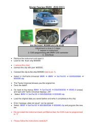
Chapter 1 • Getting StartedGetting Started<strong>Brake</strong>-<strong>Link</strong> is a multi-faceted, hand-held, <strong>ABS</strong> diagnostic tool that offers arevariety of utilities, diagnostic applications and configuration options.Component connection procedures and navigation vary depending on the utilityor application you’re using. The connection and navigation sections in thismanual are specific to the <strong>Bendix</strong> ® & <strong>Eaton</strong> ® <strong>ABS</strong> <strong>Applications</strong>.Refer to the:Figure 1.1 NEXIQ<strong>Brake</strong>-<strong>Link</strong>! Introducing <strong>Brake</strong>-<strong>Link</strong> Operator’s <strong>Manual</strong> for:— a list of safety warnings and cautions— an overview of the documentation— a formal introduction to <strong>Brake</strong>-<strong>Link</strong>— general <strong>Brake</strong>-<strong>Link</strong> connection instructions— general navigation information— GENERIC PLC TEST and RP1210A PC LINK option details— warranty and service information! The manufacturer-specific application <strong>Brake</strong>-<strong>Link</strong> manual for the controlleryou’re testing.2 NEXIQ <strong>Brake</strong>-<strong>Link</strong> <strong>Bendix</strong> ® & <strong>Eaton</strong> ® <strong>ABS</strong> <strong>Applications</strong>
Getting StartedSafety Warnings & CautionsTo protect yourself from injury and the test vehicle from damage:✔ Always wear approved eye protection.✔ Always refer to and follow the vehicle manufacturer’s WARNINGS, CAU-TIONS and service procedures.✔ Exhaust gas contains deadly poison. Always test outdoors or use properlyvented exhaust hose.✔ Keep yourself and your test equipment clear of all moving or hot engineparts.✔ Unless otherwise noted, set the parking brake and place the gear selectorin the NEUTRAL or PARK position. If the vehicle has an automaticparking brake release, temporarily disconnect the release mechanism.Also, block the drive wheels before performing a test with the engine running.✔ Unless otherwise directed, turn the ignition switch OFF before disconnectingor connecting any electrical components.✔ Read and understand this manual before operating your NEXIQ<strong>Brake</strong>-<strong>Link</strong>.✔ NEXIQ Technologies recommends having an assistant drive the vehiclewhile you use NEXIQ <strong>Brake</strong>-<strong>Link</strong> if you need to test the vehicle in transit.✔ Never leave the vehicle unattended while testing.Certain Electro-Static Discharge (ESD) and/or Electrical Fast Transient(EFT) events may lock up the NEXIQ <strong>Brake</strong>-<strong>Link</strong>. Disconnect the NEXIQ<strong>Brake</strong>-<strong>Link</strong> from the power source and re-connect to regain fulloperation.NEXIQ <strong>Brake</strong>-<strong>Link</strong> <strong>Bendix</strong> ® & <strong>Eaton</strong> ® <strong>ABS</strong> <strong>Applications</strong> 3
Using this <strong>Manual</strong>Navigation Icons<strong>Brake</strong>-<strong>Link</strong> offers two methods of navigation: menu and direct access buttons.See “Navigating <strong>Brake</strong>-<strong>Link</strong>”, on page 6. If a task can be performedwith both, the manual provides separate instructions for each method. Topicintroductions indicate when there are two sets of instructions and the followingicons help you easily locate the desired set.General IconsExhaust modulators via menu navigation:Exhaust modulators via buttons navigation:This manual also presents icons that denote specific types of peripheral information.Troubleshooting Tips help you diagnose or anticipate potential issues.Caution Tips help you avoid injury or prevent damage to NEXIQ<strong>Brake</strong>-<strong>Link</strong>.?Frequentlyasked questions, industry definitions and other relevantbackground information.NEXIQ <strong>Brake</strong>-<strong>Link</strong> <strong>Bendix</strong> ® & <strong>Eaton</strong> ® <strong>ABS</strong> <strong>Applications</strong> 5
Chapter 1 • Getting StartedNavigating <strong>Brake</strong>-<strong>Link</strong><strong>Brake</strong>-<strong>Link</strong> offers the following navigation options:• Menu navigation: use the arrow buttons to scroll through the menuscreens and select the menu options.• Buttons navigation: use the direct access buttons to access specific<strong>Brake</strong>-<strong>Link</strong> options directly.This section provides an overview of button functionality. The procedure discussionsspecify which buttons to push and when.Home ButtonUse thebutton to return to the Select Application screen.SELECT APPLICATIONG ENERIC PLC TESTBENDIX/KB/EATON <strong>ABS</strong>MERITOR WABCO <strong>ABS</strong>Enter ButtonNote: This button does not function if the screen displays “[ENTER]TO CONTINUE”.Use the button to select a menu item, confirm a response, or instruct<strong>Brake</strong>-<strong>Link</strong> to proceed to the next step.6 NEXIQ <strong>Brake</strong>-<strong>Link</strong> <strong>Bendix</strong> ® & <strong>Eaton</strong> ® <strong>ABS</strong> <strong>Applications</strong>
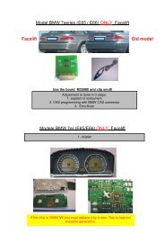
Navigating <strong>Brake</strong>-<strong>Link</strong>Menu ButtonsIf you choose MENU NAVIGATION, use the menu buttons (located below thetool’s LCD) to navigate through the menu screens.Menu buttonsFigure 1.2 Menu buttonsWhen the LCD displays a list of options,• press the or keys to scroll through the available options;Note: A dashed line displays after the last option indicating the endof the menu or list.• press• pressscreen.to select the option the blinking cursor is on;to exit your selection and return to the previous menu orNEXIQ <strong>Brake</strong>-<strong>Link</strong> <strong>Bendix</strong> ® & <strong>Eaton</strong> ® <strong>ABS</strong> <strong>Applications</strong> 7
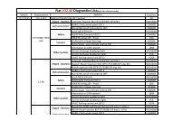
Chapter 1 • Getting StartedDirect Access ButtonsThe direct access buttons reside on the lower portion of the <strong>Brake</strong>-<strong>Link</strong>. Noticethey are grouped by functionality. The section provides a button overviewfor each button group.Note: These buttons operate differently depending on the applicationyou’re using and/or controller you’re diagnosing. This sectionprovides a cursory explanation of their functionality within the <strong>Bendix</strong>® and <strong>Eaton</strong> ® <strong>ABS</strong> <strong>Applications</strong>, per controller. Refer to theappropriate manufacturer-specific <strong>Brake</strong>-<strong>Link</strong> manual for the controlleryou’re testing.ButtongrouptagsFigure 1.3 Direct Access ButtonsCOMM ButtonsUse the COMM buttons to select the hardware/communication protocol. See“Selecting a Protocol & Registering the ECU”, on pag e25.J1708to select the J1708/J1587 BUS hardware/communication proto-Presscol.8 NEXIQ <strong>Brake</strong>-<strong>Link</strong> <strong>Bendix</strong> ® & <strong>Eaton</strong> ® <strong>ABS</strong> <strong>Applications</strong>
Navigating <strong>Brake</strong>-<strong>Link</strong>J1939is not currently implemented.PLCto select the PLC/ENHANCED MODE hardware/communica-Presstion protocol.MODE ButtonsUse the MODE buttons to select the portion of the vehicle you need to test, i.e.,Tractor or Trailer.TractorPushto select tractor.TrailerPushto select trailer.AXLE ButtonsUse the AXLE buttons to specify which axle you need to test.Note: These buttons support EC-17, EC-30 and EC-30T diagnosticsonly.The available AXLE buttons are:FrontPushto select the front axle.MidPushto select the middle axle.RearPushto select the rear axle.Note: AXLE buttons work in conjunction with the SIDE and COM-PONENT buttons.NEXIQ <strong>Brake</strong>-<strong>Link</strong> <strong>Bendix</strong> ® & <strong>Eaton</strong> ® <strong>ABS</strong> <strong>Applications</strong> 9
Chapter 1 • Getting StartedSIDE ButtonsUse the SIDE buttons to select the side of the brake system that you wish totest.Note: These buttons support EC-17, EC-30 and EC-30T diagnosticsonly.The available buttons are:LeftPushto select the left side.RightPushto select the right side.Note: SIDE buttons work in conjunction with the AXLE and COM-PONENT buttons.COMPONENT ButtonsUse the COMPONENT buttons to select the component that you wish to test.The available buttons are:TractionPushECU.to temporarily disable the traction control on a <strong>Brake</strong>-<strong>Link</strong>ModulatorNote: This button supports EC-17, EC-30 and EC-30T diagnosticsonly.Pushto access the following <strong>Brake</strong>-<strong>Link</strong> modulator tests:• CHUFF MODULATOR; see “Chuffing Modulators”, on page 60.• EXHAUST MODULATOR; see “Exhaust Modulators”, on pag e69.• HOLD MODULATOR; see “Hold Modulators”, on page 74.Note: This button supports EC-17, EC-30 and EC-30T diagnosticsonly.10 NEXIQ <strong>Brake</strong>-<strong>Link</strong> <strong>Bendix</strong> ® & <strong>Eaton</strong> ® <strong>ABS</strong> <strong>Applications</strong>
Navigating <strong>Brake</strong>-<strong>Link</strong>SensorThis button behaves differently depending on the system you’re diagnosing.For:• EC-17, EC-30 and EC-30T diagnostics, retrieves the wheelspeed for each wheel on the tractor/trailer. See “To retrieve wheelspeeds via button navigation:”, on page57.• Gen 4 and 5 controllers, this button presents the Data List which containswheel speeds. See “To access the Data List via button navigation:”,on page 116.ECUFor EC-17, EC-30 and EC-30T diagnostics, thefollowing list of options:button produces the• ECU INFORMATION; see “ECU Information”, on page 87.• SYSTEM SETUP; see “Modifying System Configuration”, on page 93.• SELF-CONFIGURATION; see “Using Self-Configuration”, on page 91.For Gen 4 and 5 diagnostics, it presents ECU Information; see “To view ECUInformation via button navigation:”, on page 102.Other ButtonsUse the following buttons to select other <strong>Brake</strong>-<strong>Link</strong> options:Current FaultsIf you’re diagnosing:• EC-17, EC-30 or EC-30T systems, use to view and/or clear allcurrent faults. See “Current Faults”, on page 45.• Gen 5 system, use it view existing faults. See “Viewing Existing Faults”,on page 104.Fault HistoryIf you’re diagnosing:• EC-17, EC-30 or EC-30T systems, usefault history. See “Fault History”, on pag e50.to view and/or clear all• Gen 4 or 5 systems, use it to view stored faults. See “Viewing StoredFaults”, on page108.NEXIQ <strong>Brake</strong>-<strong>Link</strong> <strong>Bendix</strong> ® & <strong>Eaton</strong> ® <strong>ABS</strong> <strong>Applications</strong> 11
Chapter 1 • Getting StartedResetIf you’re diagnosing:• EC-17, EC-30 or EC-30T systems,ECU”, on page 89.resets the ECU. See “Reset• Gen 4 or 5 systems, it clears all existing and/or stored fault codes fromthe controller. See “Clearing Faults”, on page 111.VOLTIf you’re diagnosing:• EC-17, EC-30 or EC-30T systems, use the button to VIEW THEBATTERY VOLTAGE (see pg. 57) or access the LOAD BATTERYTEST (see pg. 84).Note: The LED next to this button illuminates if the ECU is poweredup.• Gen 4 or 5 systems, use it to view the Data List which contains varioussystem voltage data points. See “To access the Data List via button navigation:”,on page116.12 NEXIQ <strong>Brake</strong>-<strong>Link</strong> <strong>Bendix</strong> ® & <strong>Eaton</strong> ® <strong>ABS</strong> <strong>Applications</strong>
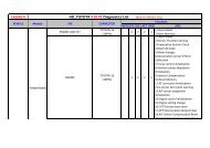
Navigating <strong>Brake</strong>-<strong>Link</strong>Light Emitting Diodes (LEDs)The POWER LED indicates <strong>Brake</strong>-<strong>Link</strong> is receiving power. The COMM andMODE LEDs light up, according to the <strong>Brake</strong>-<strong>Link</strong> operation(s) you select.When you’re diagnosing EC-17, EC-30 or EC-30T systems, the AXLE, SIDE,COMPONENT and VOLT LEDs reflect the LED illumination on the ECU’s frontpanel. Red LEDs indicate the presence of a fault code.RedFaultLEDsFigure 1.4 Light Emitting DiodesNEXIQ <strong>Brake</strong>-<strong>Link</strong> <strong>Bendix</strong> ® & <strong>Eaton</strong> ® <strong>ABS</strong> <strong>Applications</strong> 13
Chapter 1 • Getting Started14 NEXIQ <strong>Brake</strong>-<strong>Link</strong> <strong>Bendix</strong> ® & <strong>Eaton</strong> ® <strong>ABS</strong> <strong>Applications</strong>
2EstablishingConnectionConnecting <strong>Brake</strong>-<strong>Link</strong> Components, page 16uSelecting a Protocol & Registering the ECU, page 19uuEnabling Enhanced PLC Mode, page 30NEXIQ <strong>Brake</strong>-<strong>Link</strong> offers a variety of connection options. Quickly and easily attach<strong>Brake</strong>-<strong>Link</strong> to the vehicle, power up and register the ECU to begin a diagnostic session.This chapter details each step necessary to establish communication with the <strong>ABS</strong> ECU.NEXIQ <strong>Brake</strong>-<strong>Link</strong> <strong>Bendix</strong> ® & <strong>Eaton</strong> ® <strong>ABS</strong> <strong>Applications</strong> 15
Chapter 2 • Establishing ConnectionConnecting <strong>Brake</strong>-<strong>Link</strong> ComponentsConnect <strong>Brake</strong>-<strong>Link</strong> to the vehicle with one of the following adapters:• J560 PLC Cable Set. Attach to the tractor or trailer J560 Power LineConnector. Note: The ECU must be configured to support EnhancedPLC Mode in order to use this adapter.• 9-Pin Deutsch. Attach to the Deutsch Connector typically located underthe dash (driver’s side), beside the driver’s seat or near the trailer brakeECU.Choosing the appropriate adapter depends on:• whether you’re diagnosing the Tractor or Trailer;• which connectors are available on the Tractor/Trailer;• whether the Tractor is connected to the Trailer;?Do• whether the ECU is configured to support Enhanced PLC Mode.you know what Enhanced PLC Mode is?Older brake ECUs transmit diagnostic information over the J1708 Bus only(Figure 2.3, page 19)—accessing both tractor and trailer ECUs requiresindependent connections. Newer ECUs offer Enhanced PLC Mode—theycan send diagnostic information over the power line. If the tractor andtrailer are connected, access both ECUs via a single connection.16 NEXIQ <strong>Brake</strong>-<strong>Link</strong> <strong>Bendix</strong> ® & <strong>Eaton</strong> ® <strong>ABS</strong> <strong>Applications</strong>
Connecting <strong>Brake</strong>-<strong>Link</strong> ComponentsUse the following table to help you decide which adapter to use with the <strong>Bendix</strong>® & <strong>Eaton</strong> ® <strong>ABS</strong> <strong>Applications</strong>. Then look at the connection diagram andcomplete the instructions that follow the table.BENDIX & EATON <strong>ABS</strong> APPlICATIONSAre youtestingthe...TractorOnlyTrailerOnlyTractor/TrailerTogetherConnect to the...If the tractor ECU supports Enhanced PLCMode, connect to either the Deutsch or J560Power Line Connector.If it doesn’t, use the Deutsch Connector.If the trailer ECU supports Enhanced PLCMode, connect to the J560 Power Line; otherwise,connect to the Deutsch if available.If the trailer ECU supports Enhanced PLCMode, connect to the tractor Deutsch to communicatewith both ECUs via a single connection.If it doesn’t, connect to the trailer and tractorseparately via their perspective Deutsch Connectors.Note: <strong>Bendix</strong> ® Generation 5 controllers (formerly of <strong>Eaton</strong> ® ) supportEnhanced PLC Mode. EC-30 and EC-30T also support it, butmay require configuration to enable it; see “Enabling Enhanced PLCMode”, on page 30.NEXIQ <strong>Brake</strong>-<strong>Link</strong> <strong>Bendix</strong> ® & <strong>Eaton</strong> ® <strong>ABS</strong> <strong>Applications</strong> 17
Chapter 2 • Establishing ConnectionFigure 2.1 shows how to connect <strong>Brake</strong>-<strong>Link</strong> components for standard <strong>ABS</strong>diagnostics.Power/Data Cable6- or 9-Pin DeutschNote: Where applicable,substitute withJ560 PLC Cable Set(Figure 2.2)Figure 2.1 Connectivity diagram for standard <strong>ABS</strong>diagnostics.Use the J560 PLC Cable Set in place of the Deutsch adapter if you plan to attachto the tractor or trailer’s power line connector.QuickDisconnectFigure 2.2 J560 PLC Cable SetTo connect <strong>Brake</strong>-<strong>Link</strong> components:1 Attach the Power/Data Cable DB15 Connector to the data port (labelledTo Vehicle) on the <strong>Brake</strong>-<strong>Link</strong>; tighten the thumbscrews.18 NEXIQ <strong>Brake</strong>-<strong>Link</strong> <strong>Bendix</strong> ® & <strong>Eaton</strong> ® <strong>ABS</strong> <strong>Applications</strong>
Selecting a Protocol & Registering the ECU2 Plug the Data Cable Atari End into the Atari End on the cable you attachto the vehicle, i.e., Deutsch adapter or J560 PLC Cable Set.3 Attach the vehicle interface cable to the vehicle.— If you’re using the J560 PLC Cable Set, plug into the Power LineConnector on the outside of the tractor or trailer.— If you’re using the Deutsch Adapter, plug into the Deutsch Connectortypically located under the dash on the driver’s side, beside the driver’sseat or near the brake ECU on the trailer.Note: Not all trailers are equipped with Deutsch Connectors.4 If you’re using the J560 PLC Cable Set to attach to the trailer, connectthe alligator clips to an external power supply; otherwise, turn the tractor’skey to the “on” position.Selecting a Protocol & Registering the ECUNEXIQ <strong>Brake</strong>-<strong>Link</strong> uses the SAE J1587 communication protocol to interactwith the vehicle’s brake controllers. It sends and receives diagnostic information(i.e., J1587 messages) over the:• J1708 BusorIf you’re connecting to a tractor, use the Quick Disconnect(Figure 2.2) to remove the alligator clips from the cable set first.Since the tractor provides power, the alligator clips areunnecessary and could potentially cause a short.• Power Line Carrier (PLC) (only available if the ECU(s) support EnhancedPLC Mode; see pg .30)DeutschConnectorJ1708 BusPower Line Carrier (PLC)Trailer ECUJ1708 BusTractor ECUPower Line ConnectorsDeutschConnectorFigure 2.3 Power Line Carrier and J1708 Bus IllustrationNEXIQ <strong>Brake</strong>-<strong>Link</strong> <strong>Bendix</strong> ® & <strong>Eaton</strong> ® <strong>ABS</strong> <strong>Applications</strong> 19
Chapter 2 • Establishing ConnectionThese data bus options provide several ways to access brake ECUs. For example,if you’re testing a trailer that does not have a Deutsch Connector, usethe J560 PLC Cable Set to obtain information over the power line.20 NEXIQ <strong>Brake</strong>-<strong>Link</strong> <strong>Bendix</strong> ® & <strong>Eaton</strong> ® <strong>ABS</strong> <strong>Applications</strong>
Selecting a Protocol & Registering the ECUBoth <strong>Bendix</strong> ® and <strong>Eaton</strong> ® <strong>ABS</strong> <strong>Applications</strong> require you to select a hardware/communication protocol in order to establish a connection to the ECU. In otherwords, you must tell <strong>Brake</strong>-<strong>Link</strong> which Data Bus to use for communications:J1708/J1587 BUS or PLC/ENHANCED MODE. Use the following table to helpyou decide which protocol best suites your needs.J1708/J1587PLC/EnhancedModeBenefits:• provides ECU access via a standard Deutsch connection• supported by all <strong>Bendix</strong> ® brake ECUsConsiderations:• ECU access typically requires connecting to thetractor and trailer separately• some trailers do not provide Deutsch connectors• if you’re diagnosing a trailer that isn’t connected to atractor, an external power supply and adapter is requiredin addition to the Deutsch adapterUse if:• the ECU you’re testing doesn’t support EnhancedPLC Mode, i.e., Gen 4 or EC-17• the ECU you’re testing supports, but is not configuredfor, Enhanced PLC Mode; once you enable it,you can use either protocolBenefits:• provides ECU access via a Deutsch or J560 PowerLine Connection• if the tractor is attached to the trailer, it provides accessto both ECUs via a single connection• provides access to the trailer ECU if there is noDeutsch Connector availableConsiderations:• the applicable ECU(s) must support Enhanced PLCMode (see pg. 30) to utilize this protocolUse if:• the tractor is connected to the trailer and you needto communicate with the trailer or both ECUs• there is no Deutsch Connector available on the trailer• you’re testing a trailer that is not connected to a tractorNEXIQ <strong>Brake</strong>-<strong>Link</strong> <strong>Bendix</strong> ® & <strong>Eaton</strong> ® <strong>ABS</strong> <strong>Applications</strong> 21
Chapter 2 • Establishing ConnectionOnce you connect <strong>Brake</strong>-<strong>Link</strong> to the vehicle, choose the application, selecta navigation method & hardware/communication protocol, <strong>Brake</strong>-<strong>Link</strong> attemptsto establish communication with the ECU. This process is called ECUregistration. The discussions in Chapter 3 & 4 assume that you have registeredthe ECU. The rest of this section explains how to register the ECU using eachnavigation method.Register ECU via menu navigation:1 Connect <strong>Brake</strong>-<strong>Link</strong> to the tractor or trailer and power-up (see “Connecting<strong>Brake</strong>-<strong>Link</strong> Components”, on page 16).2 <strong>Brake</strong>-<strong>Link</strong> boots up and presents the Select Application screen.SELECT APPLICATIONGENERIC PLC TESTBENDIX/KB/EATON <strong>ABS</strong>MERITOR WABCO <strong>ABS</strong>Use the and keys to select BENDIX/KB/EATON <strong>ABS</strong> orEATON <strong>ABS</strong>; press .Note: EATON <strong>ABS</strong> exclusively supports Generation 4 & 5 controllers(formerly marketed by <strong>Eaton</strong> ® ); BENDIX <strong>ABS</strong> supports EC-17,EC-30, EC-30T, and Generation 4 & 5.3 <strong>Brake</strong>-<strong>Link</strong> displays navigation options; use the andkeys to select MENU NAVIGATION and press .22 NEXIQ <strong>Brake</strong>-<strong>Link</strong> <strong>Bendix</strong> ® & <strong>Eaton</strong> ® <strong>ABS</strong> <strong>Applications</strong>
Selecting a Protocol & Registering the ECU4 The Protocol Selection screen displays.ProtocolSelectionsJ1708/J1587 BUSPLC/ENHANCED MODESET ENHANCE PLC MODEUse the and keys to select the desired option:— J1708/J1587 BUS configures <strong>Brake</strong>-<strong>Link</strong> to communicate with theECU via the J1708 Bus (accessed through the standard DeutschConnection). Go to step 5.— PLC/ENHANCED MODE configures <strong>Brake</strong>-<strong>Link</strong> to communicatewith the ECU(s) via the Power Line Carrier (accessed through theDeutsch or J560 Tractor/Trailer Power Line Connections). This optionrequires Enhanced Mode support and configuration of theECU(s). See “Enabling Enhanced PLC Mode”, on page 30. Go tostep 6.— SET ENHANCE PLC MODE enables Enhanced PLC Mode on theECU, providing the ECU is equipped with Enhanced Mode capability.See “Enabling Enhanced PLC Mode”, on page 30.Note: This menu item only appears if you selected BENDIX/KB/EATON <strong>ABS</strong>.Press .Configuration option that enables the PLC/Enhanced Mode (see pg. 30).NEXIQ <strong>Brake</strong>-<strong>Link</strong> <strong>Bendix</strong> ® & <strong>Eaton</strong> ® <strong>ABS</strong> <strong>Applications</strong> 23
Chapter 2 • Establishing Connection5 If you selected J1708/J1587 BUS, <strong>Brake</strong>-<strong>Link</strong> auto-detects the <strong>Bendix</strong>® (and/or formerly <strong>Eaton</strong> ® ) ECUs present on the J1708 Bus. If itfinds a Tractor and Trailer ECU, it prompts you to select TRACTOR orTRAILER; use the and keys to select the desired optionand press .<strong>Brake</strong>-<strong>Link</strong> then presents an ECU Registration screen. The informationon this screen varies depending on the controller.EC-17/30/30T Registration screens show ECU ID, sensor/modulatorconfiguration and indicate whether there are active faults; if there are,<strong>Brake</strong>-<strong>Link</strong> illuminates the LEDs on the front panel to reflect theLED illumination on the ECU itself.BENDIX TRAILER2S/1M EC30TACTIVE FAULTS EXIST[ENTER] TO CONTINUEGeneration 4/5 Registration screens show ECU ID and indicatewhether there are Existing (Gen 5 only) and/or Stored Faults.TRAILER <strong>ABS</strong> GEN 5EXISTING FAULTS YESSTORED FAULTS YES[ENTER] TO CONTINUEPress to access the application main menu; refer to Chapter 3,"Diagnosing EC-17, EC-30 & EC-30T <strong>ABS</strong>" or Chapter 4, "DiagnosingGen 4 & 5 <strong>ABS</strong>".24 NEXIQ <strong>Brake</strong>-<strong>Link</strong> <strong>Bendix</strong> ® & <strong>Eaton</strong> ® <strong>ABS</strong> <strong>Applications</strong>
Selecting a Protocol & Registering the ECUIf you selected BENDIX/KB/EATON <strong>ABS</strong> and <strong>Brake</strong>-<strong>Link</strong>presents CAN NOT IDENTIFY ECU:• the detected ECU is not a <strong>Bendix</strong> ® EC-17, EC-30, EC-30T, Generation4, or Generation 5 controller.If you selected EATON <strong>ABS</strong> and <strong>Brake</strong>-<strong>Link</strong> presents CAN NOTIDENTIFY ECU:• the detected ECU is not a <strong>Bendix</strong> ® Generation 4 or Generation 5controller (formerly marketed by <strong>Eaton</strong> ® ).If it returns ECU NOT RESPONDING:• you may have a loose connection; check all cables and reboot<strong>Brake</strong>-<strong>Link</strong>.• the ECU or Data Bus may not be working properly.NEXIQ <strong>Brake</strong>-<strong>Link</strong> <strong>Bendix</strong> ® & <strong>Eaton</strong> ® <strong>ABS</strong> <strong>Applications</strong> 25
Chapter 2 • Establishing Connection6 If you selected PLC/ENHANCED MODE, <strong>Brake</strong>-<strong>Link</strong> auto-detectsthe <strong>Bendix</strong> ® (and/or formerly <strong>Eaton</strong> ® ) ECUs present on the J1708 Bus.If it finds a tractor and trailer ECU, it prompts you to select TRACTOR orTRAILER; use the and keys to select the desired optionand press .<strong>Brake</strong>-<strong>Link</strong> then presents an ECU Registration screen. The informationon this screen varies depending on the controller.EC-17/30/30T Registration screens show ECU ID, sensor/modulatorconfiguration and indicate whether there are active faults; if there are,<strong>Brake</strong>-<strong>Link</strong> illuminates the LEDs on the front panel to reflect theLED illumination on the ECU itself.BENDIX TRAILER2S/1M EC30TACTIVE FAULTS EXIST[ENTER] TO CONTINUEGeneration 4/5 Registration screens show ECU ID and indicatewhether there are Existing (Gen 5 only) and/or Stored Faults.TRAILER <strong>ABS</strong> GEN 5EXISTING FAULTS YESSTORED FAULTS YES[ENTER] TO CONTINUEPress to access the application main menu; refer to Chapter 3,"Diagnosing EC-17, EC-30 & EC-30T <strong>ABS</strong>" or Chapter 4, "DiagnosingGen 4 & 5 <strong>ABS</strong>".26 NEXIQ <strong>Brake</strong>-<strong>Link</strong> <strong>Bendix</strong> ® & <strong>Eaton</strong> ® <strong>ABS</strong> <strong>Applications</strong>
Selecting a Protocol & Registering the ECUf you selected BENDIX/KB/EATON <strong>ABS</strong> and <strong>Brake</strong>-<strong>Link</strong> presentsCAN NOT IDENTIFY ECU:• the detected ECU is not a <strong>Bendix</strong> ® EC-17, EC-30, EC-30T, Generation4, or Generation 5 controller.If you selected EATON <strong>ABS</strong> and <strong>Brake</strong>-<strong>Link</strong> presents CAN NOTIDENTIFY ECU:• the detected ECU is not a <strong>Bendix</strong> ® Generation 4 or Generation 5controller (formerly marketed by <strong>Eaton</strong> ® ).If it displays ECU NOT RESPONDING:• you may have a loose connection; check all cables and reboot<strong>Brake</strong>-<strong>Link</strong>.• the brake ECU may not equipped with Enhanced PLC Mode; connectto the tractor/trailer Deutsch and select the J1708/J1587 protocol.• Enhanced PLC Mode may not be enabled (see “Enabling EnhancedPLC Mode”, on page 30).• the ECU or Data Bus may be malfunctioning.Register ECU via direct access buttons:1 Connect <strong>Brake</strong>-<strong>Link</strong> to the tractor or trailer and power-up (see “Connecting<strong>Brake</strong>-<strong>Link</strong> Components”, on page 16).2 <strong>Brake</strong>-<strong>Link</strong> boots up and presents the Select Application screen.SELECT APPLICATIONGENERIC PLC TESTBENDIX/KB/EATON <strong>ABS</strong>MERITOR WABCO <strong>ABS</strong>Use the and keys to select BENDIX/KB/EATON <strong>ABS</strong> orEATON <strong>ABS</strong>; press .Note: EATON <strong>ABS</strong> exclusively supports Generation 4 & 5 controllers(formerly marketed by <strong>Eaton</strong> ® ); BENDIX <strong>ABS</strong> supports EC-17,EC-30, EC-30T, and Generation 4 & 5.NEXIQ <strong>Brake</strong>-<strong>Link</strong> <strong>Bendix</strong> ® & <strong>Eaton</strong> ® <strong>ABS</strong> <strong>Applications</strong> 27
Chapter 2 • Establishing Connection3 <strong>Brake</strong>-<strong>Link</strong> displays navigation options; use the andkeys to select BUTTON NAVIGATION and press .4 <strong>Brake</strong>-<strong>Link</strong> prompts you to press the appropriate COMM button;press:— to configure <strong>Brake</strong>-<strong>Link</strong> to communicate with the ECU viathe J1708 Bus (accessed through the standard Deutsch Connectors).— to configure <strong>Brake</strong>-<strong>Link</strong> to communicate with the ECU(s)via the Power Line Carrier (accessed through the Deutsch or J560Tractor/Trailer Power Line Connectors).Note: This option requires Enhanced Mode support and configurationof the ECU(s). See “Enabling Enhanced PLC Mode”, onpage 30.5 Next, <strong>Brake</strong>-<strong>Link</strong> prompts you to select a MODE; press or.6 <strong>Brake</strong>-<strong>Link</strong> then presents an ECU Registration screen. The informationon this screen varies depending on the controller.EC-17/30/30T Registration screens show ECU ID, sensor/modulatorconfiguration and indicate whether there are active faults; if there are,<strong>Brake</strong>-<strong>Link</strong> illuminates the LEDs on the front panel to reflect theLED illumination on the ECU itself.BENDIX TRAILER2S/1M EC30TACTIVE FAULTS EXIST[ENTER] TO CONTINUEGeneration 4/5 Registration screens show ECU ID and indicatewhether there are Existing (Gen 5 only) and/or Stored Faults.TRAILER <strong>ABS</strong> GEN 5EXISTING FAULTS YESSTORED FAULTS YES[ENTER] TO CONTINUE28 NEXIQ <strong>Brake</strong>-<strong>Link</strong> <strong>Bendix</strong> ® & <strong>Eaton</strong> ® <strong>ABS</strong> <strong>Applications</strong>
Selecting a Protocol & Registering the ECUPress ; refer to Chapter 3, "Diagnosing EC-17, EC-30 & EC-30T<strong>ABS</strong>" or Chapter 4, "Diagnosing Gen 4 & 5 <strong>ABS</strong>".If you selected BENDIX/KB/EATON <strong>ABS</strong> and <strong>Brake</strong>-<strong>Link</strong>presents CAN NOT IDENTIFY ECU:• the detected ECU is not a <strong>Bendix</strong> ® EC-17, EC-30, EC-30T, Generation4, or Generation 5 controller.If you selected EATON <strong>ABS</strong> and <strong>Brake</strong>-<strong>Link</strong> presents CAN NOTIDENTIFY ECU:• the detected ECU is not a <strong>Bendix</strong> ® Generation 4 or Generation 5controller (formerly marketed by <strong>Eaton</strong> ® ).If it returns ECU NOT RESPONDING and you’re using theprotocol:• <strong>Brake</strong>-<strong>Link</strong> can’t find a supported ECU for the selectedMODE, e.g., you chose trailer while attached to the tractor andthe tractor and trailer ECUs reside on separate J1708 Buses.Connect to the desired J1708 Bus and start again.• you may have a loose connection; check all cables and reboot theapplication.• the ECU or Data Bus may not be working properly.If it presents ECU NOT RESPONDING and you’re using theprotocol:• the brake ECU may not be equipped with Enhanced PLC Mode;attach <strong>Brake</strong>-<strong>Link</strong> to the applicable Deutsch Connector (i.e.,tractor or trailer) and use the protocol.• Enhanced PLC Mode may not be enabled on the ECU. Attach<strong>Brake</strong>-<strong>Link</strong> to the applicable Deutsch Connector (i.e., tractoror trailer) and use the protocol; then, see “Enabling EnhancedPLC Mode”, on page 30.• the ECU or Data Bus may be malfunctioning.7 <strong>Brake</strong>-<strong>Link</strong> instructs you to CONTINUE BY PRESSING BUTTONS.Refer to the “Table of Contents” to find information on the tasks youwish to perform for the system you’re diagnosing or configuring.NEXIQ <strong>Brake</strong>-<strong>Link</strong> <strong>Bendix</strong> ® & <strong>Eaton</strong> ® <strong>ABS</strong> <strong>Applications</strong> 29
Chapter 2 • Establishing ConnectionEnabling Enhanced PLC Mode<strong>ABS</strong> controllers that are equipped with Enhanced PLC Mode can send diagnosticinformation over the tractor/trailer power lines. This feature makes itpossible to:• access all ECUs residing on the power line via a single diagnostic connection.For example, if the Tractor and Trailer are connected, attach<strong>Brake</strong>-<strong>Link</strong> to the Tractor Deutsch to access both Tractor and Trailer<strong>ABS</strong> ECUs.• access a Trailer <strong>ABS</strong> ECU when a Deutsch Connector isn’t available. Italso makes Trailer ECU access more convenient, as you only need oneadapter (J560 PLC Cable Set) to supply power and communicate withthe ECU.<strong>Bendix</strong> ® EC-30 and EC-30T controllers may require configuration to enableEnhanced PLC Mode. The rest of this section details enabling EnhancedMode.To enable Enhanced PLC Mode:1 Connect <strong>Brake</strong>-<strong>Link</strong> to the Tractor or Trailer Deutsch Connector (see“Connecting <strong>Brake</strong>-<strong>Link</strong> Components”, on page 16).Note: Some ECUs support Enhanced Mode configuration over thePLC. In other words, if the trailer is attached to the tractor, you maybe able to configure both ECUs through a single connection to thetractor Deutsch. If you receive an ECU NOT RESPONDING message,connect <strong>Brake</strong>-<strong>Link</strong> to the trailer Deutsch and try again.2 Turn the tractor key “on”. <strong>Brake</strong>-<strong>Link</strong> boots up and presents theSelect Application screen.SELECT APPLICATIONGENERIC PLC TESTBENDIX/KB/EATON <strong>ABS</strong>MERITOR WABCO <strong>ABS</strong>Use the and keys to select BENDIX/KB/EATON <strong>ABS</strong>;press .30 NEXIQ <strong>Brake</strong>-<strong>Link</strong> <strong>Bendix</strong> ® & <strong>Eaton</strong> ® <strong>ABS</strong> <strong>Applications</strong>
Enabling Enhanced PLC ModeNote: If <strong>Brake</strong>-<strong>Link</strong> has already registered an ECU and youreturned to this screen by pressing , press ; then,select BENDIX/KB/EATON <strong>ABS</strong>.3 <strong>Brake</strong>-<strong>Link</strong> presents navigation options; use the andkeys to select MENU NAVIGATION; press .4 <strong>Brake</strong>-<strong>Link</strong> displays the following screen; use the andkeys to select SET ENHANCE PLC MODE and press .J1708/J1587 BUSPLC/ENHANCED MODES ET ENHANCE PLC MODE5 <strong>Brake</strong>-<strong>Link</strong> prompts you to select TRACTOR or TRAILER; use theand keys to select the desired option and press .6 Next, <strong>Brake</strong>-<strong>Link</strong> displays your tractor/trailer selection and asks ifyou’d like to enable Enhanced PLC Mode permanently (PERM) or forthe current ignition cycle (TEMP); use the and keys toselect the desired option and press .SET ENHANCE PLC MODETRAILERPERM [TEMP]7 <strong>Brake</strong>-<strong>Link</strong> confirms the configuration is complete.If it returns ECU NOT RESPONDING:• the ECU may not be a <strong>Bendix</strong> ® EC-30 or EC-30T; perform anECU Registration (see pg. 19) to determine the type of ECU.• the ECU may not support Enhanced PLC Mode.• you may have selected the incorrect MODE, e.g., you’re connectedto the Trailer Deutsch and selected Tractor Mode.• the ECU or Data Bus may not be working properly.8 Press to return to the Protocol Selection screen.NEXIQ <strong>Brake</strong>-<strong>Link</strong> <strong>Bendix</strong> ® & <strong>Eaton</strong> ® <strong>ABS</strong> <strong>Applications</strong> 31
Chapter 2 • Establishing Connection32 NEXIQ <strong>Brake</strong>-<strong>Link</strong> <strong>Bendix</strong> ® & <strong>Eaton</strong> ® <strong>ABS</strong> <strong>Applications</strong>
3DiagnosingEC-17, EC-30 &EC-30T <strong>ABS</strong>Using EC-17, EC-30 & EC-30T Diagnostic Options, page 34u<strong>Brake</strong>-<strong>Link</strong> offers the <strong>Bendix</strong> ® <strong>ABS</strong> Application for diagnosing and/or configuring<strong>Bendix</strong> ® Anti-lock Braking Systems controlled by the following ECUs:Trailer• EC-30T• Generation 4 (formerly of <strong>Eaton</strong> ® )Tractor• EC-17• EC-30• Generation 5 (formerly of <strong>Eaton</strong> ® )This chapter explains how to use the <strong>Bendix</strong> ® <strong>ABS</strong> Application to diagnose systems controlledby EC-17, EC-30 or EC-30T. See Chapter 4, "Diagnosing Gen 4 & 5 <strong>ABS</strong>" for instructionson diagnosing Generation 4 and 5 <strong>ABS</strong> systems.NEXIQ <strong>Brake</strong>-<strong>Link</strong> <strong>Bendix</strong> ® & <strong>Eaton</strong> ® <strong>ABS</strong> <strong>Applications</strong> 33
Chapter 3 • Diagnosing EC-17, EC-30 & EC-30T <strong>ABS</strong>Note: Diagnostic functionality differs depending on the controller.Register the ECU (see pg. 25) to determine which controller you’reworking with; then, refer to the appropriate chapter.<strong>Bendix</strong> ® <strong>ABS</strong> Application supports both methods of navigation (see pg. 8).Most discussions in this chapter provide a separate set of instructions for eachmethod. Topic introductions indicate when there are two sets of instructionsand the following icons help you easily locate the desired set.To exhaust modulators via menu navigation:To exhaust modulators via buttons navigation:Using EC-17, EC-30 & EC-30T Diagnostic OptionsThe following table shows the all of the options available for diagnosing systemscontrolled by EC-17, EC-30 and/or EC-30T. It also indicates the numberof items offered by each option, e.g., the TESTS menu offers 11 tests.EC-17/30/30T Options# of ItemsCURRENT FAULTS (see pg. 34) 2FAULT HISTORY (see pg. 38) 2DATA LIST (see pg. 40) 1TESTS (see pg. 44) 11ECU INFORMATION (see pg. 63) 1RESET ECU (see pg. 65) 1CONFIGURATION (see pg. 66) 2The rest of this discussion details each of these options.Current Faults<strong>Brake</strong>-<strong>Link</strong> offers an option to view or clear all active (current) fault codes.Some ECUs do not clear active fault codes immediately after you make a repair.For example, a fault may continue to exist until the vehicle reaches a certainspeed. To ensure the repair corrected the issue, clear all codes; then viewall codes again. If the repair did not fix the problem, the fault code re-appears.34 NEXIQ <strong>Brake</strong>-<strong>Link</strong> <strong>Bendix</strong> ® & <strong>Eaton</strong> ® <strong>ABS</strong> <strong>Applications</strong>
Using EC-17, EC-30 & EC-30T Diagnostic OptionsViewing & Clearing All Active Fault CodesThis section explains how to view and clear all active fault codes for each navigationmethod.To view/clear all active fault codes via menu navigation:1 Connect <strong>Brake</strong>-<strong>Link</strong> to the tractor or trailer and power-up (see “Connecting<strong>Brake</strong>-<strong>Link</strong> Components”, on page 20).2 Register the ECU (see “Register ECU via menu navigation:”, onpage 28).3 <strong>Brake</strong>-<strong>Link</strong> presents the EC-17/30/30T Diagnostic Options menu; usethe and keys to scroll to CURRENT FAULTS and press.C URRENT FAULTSFAULT HISTORYDATA LISTTESTS4 <strong>Brake</strong>-<strong>Link</strong> prompts you to select VIEW ALL or CLEAR ALL. Usethe and keys to select the desired option and press.NEXIQ <strong>Brake</strong>-<strong>Link</strong> <strong>Bendix</strong> ® & <strong>Eaton</strong> ® <strong>ABS</strong> <strong>Applications</strong> 35
Chapter 3 • Diagnosing EC-17, EC-30 & EC-30T <strong>ABS</strong>5 If you select VIEW ALL, <strong>Brake</strong>-<strong>Link</strong> presents the active faults one ata time. <strong>Brake</strong>-<strong>Link</strong> continuously queries for faults; the display updatesas new faults are detected or existing faults are resolved. An arrowappears on the last line of the display if there is more than one fault; usethe and keys to scroll through the fault codes. Pressto return to the VIEW ALL/CLEAR ALL selection dialogLine 1:DeviceLine 2 & 3: FaultDescriptionTRACTION MODOPENSID:12 FMI:05 x1↓Indicatesthere aremorefaults.Sub-system IDFailureMode IdentifierOccurrenceNote: Some fault code descriptions, as defined by <strong>Bendix</strong> ® , arelonger than the LCD line. See Appendix A, “EC-17, EC-30 & EC-30TSID/FMI Tables”, for complete fault descriptions.If you select CLEAR ALL, <strong>Brake</strong>-<strong>Link</strong> prompts you for confirmation.Use the and keys to select YES or NO and press .— NO returns you to the VIEW ALL/CLEAR ALL selection dialog.— YES clears the faults; press to return to the VIEW ALL/CLEAR ALL selection dialog.To view/clear all active fault codes via button navigation:1 Connect <strong>Brake</strong>-<strong>Link</strong> to the tractor or trailer and power-up (see “Connecting<strong>Brake</strong>-<strong>Link</strong> Components”, on page 20).2 Register the ECU (see “Register ECU via menu navigation:”, onpage 28).3 <strong>Brake</strong>-<strong>Link</strong> instructs you to CONTINUE BY PRESSING BUTTONS;press .4 <strong>Brake</strong>-<strong>Link</strong> prompts you to select VIEW ALL or CLEAR ALL. Usethe and keys to select the desired option and press.36 NEXIQ <strong>Brake</strong>-<strong>Link</strong> <strong>Bendix</strong> ® & <strong>Eaton</strong> ® <strong>ABS</strong> <strong>Applications</strong>
Using EC-17, EC-30 & EC-30T Diagnostic Options5 If you select VIEW ALL, <strong>Brake</strong>-<strong>Link</strong> presents the active faults one ata time. <strong>Brake</strong>-<strong>Link</strong> continuously queries for fault codes; the displayupdates as new faults are detected or existing faults are resolved. Anarrow appears on the last line of the display if there is more than onefault; use the and keys to scroll through the fault codes.Press to return to the VIEW ALL/CLEAR ALL selection dialog.Line 1:DeviceLine 2 & 3: FaultDescriptionTRACTION MODOPENSID:12 FMI:05 x1↓Indicatesthere aremorefaults.Sub-system IDFailureMode IdentifierOccurrenceNote: Some fault code descriptions, as defined by <strong>Bendix</strong> ® , arelonger than the LCD line. See Appendix A, “EC-17, EC-30 & EC-30TSID/FMI Tables”, for complete fault descriptions.If you select CLEAR ALL, <strong>Brake</strong>-<strong>Link</strong> prompts you for confirmation.Use the and keys to select YES or NO and press .— NO returns you to the VIEW ALL/CLEAR ALL selection dialog.— YES clears the faults; press to return to the VIEW ALL/CLEAR ALL selection dialog.NEXIQ <strong>Brake</strong>-<strong>Link</strong> <strong>Bendix</strong> ® & <strong>Eaton</strong> ® <strong>ABS</strong> <strong>Applications</strong> 37
Chapter 3 • Diagnosing EC-17, EC-30 & EC-30T <strong>ABS</strong>Fault HistoryUse FAULT HISTORY to view or clear all inactive (historical) fault codes.Note: If you clear current (active) fault codes (see pg. 35), the ECUtypically records those fault codes in the fault history.Viewing & Clearing All Inactive Fault CodesThis section explains how to view and clear all inactive fault codes for eachnavigation method.To view/clear all inactive fault codes via menu navigation:1 Connect <strong>Brake</strong>-<strong>Link</strong> to the tractor or trailer and power-up (see “Connecting<strong>Brake</strong>-<strong>Link</strong> Components”, on page 20).2 Register the ECU (see “Register ECU via menu navigation:”, onpage 28).3 <strong>Brake</strong>-<strong>Link</strong> presents the EC-17/30/30T Diagnostic Options menu; usethe and keys to scroll to FAULT HISTORY and press.CURRENT FAULTSF AULT HISTORYDATA LISTTESTS4 <strong>Brake</strong>-<strong>Link</strong> prompts you to select VIEW ALL or CLEAR ALL. Usethe and keys to select the desired option and press.38 NEXIQ <strong>Brake</strong>-<strong>Link</strong> <strong>Bendix</strong> ® & <strong>Eaton</strong> ® <strong>ABS</strong> <strong>Applications</strong>
Using EC-17, EC-30 & EC-30T Diagnostic Options5 If you select VIEW ALL, <strong>Brake</strong>-<strong>Link</strong> presents the inactive faults oneat a time. An arrow appears on the last line of the display if there ismore than one fault; use the and keys to scroll through thefault codes. Press to return to the VIEW ALL/CLEAR ALL selectiondialogLine 1:DeviceLine 2 & 3: FaultDescriptionTRACTION MODOPENSID:12 FMI:05↓Indicatesthere aremorefaults.Sub-system IDFailure ModeIdentifierNote: Some fault code descriptions, as defined by <strong>Bendix</strong> ® , arelonger than the LCD line. See Appendix A, “EC-17, EC-30 & EC-30TSID/FMI Tables”, for ECU specific fault descriptions.If you select CLEAR ALL, <strong>Brake</strong>-<strong>Link</strong> prompts you for confirmation.Use the and keys to select YES or NO and press .— NO returns you to the VIEW ALL/CLEAR ALL selection dialog.— YES clears the faults; press to return to the VIEW ALL/CLEAR ALL selection dialog.To view/clear all inactive fault codes via button navigation:1 Connect <strong>Brake</strong>-<strong>Link</strong> to the tractor or trailer and power-up (see “Connecting<strong>Brake</strong>-<strong>Link</strong> Components”, on page 20).2 Register the ECU (see “Register ECU via menu navigation:”, onpage 28).3 <strong>Brake</strong>-<strong>Link</strong> instructs you to CONTINUE BY PRESSING BUTTONS;press .4 <strong>Brake</strong>-<strong>Link</strong> prompts you to select VIEW ALL or CLEAR ALL. Usethe and keys to select the desired option and press.NEXIQ <strong>Brake</strong>-<strong>Link</strong> <strong>Bendix</strong> ® & <strong>Eaton</strong> ® <strong>ABS</strong> <strong>Applications</strong> 39
Chapter 3 • Diagnosing EC-17, EC-30 & EC-30T <strong>ABS</strong>5 If you select VIEW ALL, <strong>Brake</strong>-<strong>Link</strong> presents the inactive faults oneat a time. An arrow appears on the last line of the display if there ismore than one fault; use the and keys to scroll through thefault codes. <strong>Brake</strong>-<strong>Link</strong> displays NO FAULTS if there are no historicalfaults. Press to return to the VIEW ALL/CLEAR ALL selection dialog.Line 1:DeviceLine 2 & 3: FaultDescriptionTRACTION MODOPENSID:12 FMI:05↓Indicatesthere aremorefaults.Sub-system IDFailure ModeIdentifierNote: Some fault code descriptions, as defined by <strong>Bendix</strong> ® , arelonger than the LCD line. See Appendix A, “EC-17, EC-30 & EC-30TSID/FMI Tables”, for complete fault descriptions.If you select CLEAR ALL, <strong>Brake</strong>-<strong>Link</strong> prompts you for confirmation.Use the and keys to select YES or NO and press .— NO returns you to the VIEW ALL/CLEAR ALL selection dialog.Data List— YES clears the faults; press to return to the VIEW ALL/CLEAR ALL selection dialog.The DATA LIST option displays information gathered by the ECU. The followingtable provides a list of the all available data items and indicates whichECUs present the given data item.Data Item Description ECU SupportLF Wheel * Left Front Wheel Speed EC-17/30/30TRF Wheel * Right Front Wheel Speed EC-17/30/30TLR Wheel * Left Rear Wheel Speed EC-17/30/30TRR Wheel * Right Rear Wheel Speed EC-17/30/30TLM Wheel * Left Middle Wheel Speed EC-17/3040 NEXIQ <strong>Brake</strong>-<strong>Link</strong> <strong>Bendix</strong> ® & <strong>Eaton</strong> ® <strong>ABS</strong> <strong>Applications</strong>
Using EC-17, EC-30 & EC-30T Diagnostic OptionsData Item Description ECU SupportRM Wheel * Right Middle Wheel Speed EC-17/30Batt Voltage * Battery Voltage EC-17/30/30TTractionLampWarningLampRetarderRelayEngineDatalinkJ1922 EngCommJ1939 EngCommJ1939 EngRetJ1939 ExhRetJ1939 DRLNRetJ1939 TransRetPLC Status †Traction Lamp StatusWarning Lamp StatusRetarder Relay StatusEngine Datalink StatusJ1922 Engine CommunicationStatusJ1939 Engine CommunicationStatusJ1939 Engine Retarder CommunicationStatusJ1939 Exhaust Retarder CommunicationsStatusJ1939 Driveline RetarderCommunications StatusJ1939 Transmission RetarderCommunication StatusTrailer Communication StatusOver J2497EC-17/30EC-17/30/30TEC-17/30EC-17/30EC-30EC-30EC-30EC-30EC-30EC-30EC-30Odometer Trailer Odometer EC-30T* You may also retrieve these Data Items via Direct Access Buttons.† PLC Status indicates whether the tractor ECU is configured to supportJ2497 communications. See Chapter 3, “Using Generic PLC Test”, inthe “Introducing <strong>Brake</strong>-<strong>Link</strong> Operator’s <strong>Manual</strong>”.Use menu navigation to access a complete data list; use direct access buttonsto retrieve Wheel Speed and/or Battery Voltage. The rest of this sectionexplains how to complete all three of these tasks.NEXIQ <strong>Brake</strong>-<strong>Link</strong> <strong>Bendix</strong> ® & <strong>Eaton</strong> ® <strong>ABS</strong> <strong>Applications</strong> 41
Chapter 3 • Diagnosing EC-17, EC-30 & EC-30T <strong>ABS</strong>To access a complete Data List via menu navigation:1 Connect <strong>Brake</strong>-<strong>Link</strong> to the tractor or trailer and power-up (see “Connecting<strong>Brake</strong>-<strong>Link</strong> Components”, on page 20).2 Register the ECU (see “Register ECU via menu navigation:”, onpage 28).3 <strong>Brake</strong>-<strong>Link</strong> presents the EC-17/30/30T Diagnostic Options menu; usethe and keys to scroll to DATA LIST and press .CURRENT FAULTSFAULT HISTORYD ATA LISTTESTS4 The Data List displays. Scroll through the data items with the andkeys.BATT VOLTAGE 14.2vTRACTION LAMP ONWARNING LAMPONRETARDER RELAY NOAV5 For each data item, <strong>Brake</strong>-<strong>Link</strong> returns:— N/A if the ECU does not respond to the data request.— NOAV if the ECU is configured to return “not available” for the givendata item.— a value applicable to the given data request, e.g., 65mph for wheelspeed.— ERROR if the ECU detects an error with the parameter or device.6 Press to return to the EC-17/30/30T Diagnostic Options menu orto return to the Select Application screen.To retrieve wheel speeds via button navigation:1 Connect <strong>Brake</strong>-<strong>Link</strong> to the tractor or trailer and power-up (see “Connecting<strong>Brake</strong>-<strong>Link</strong> Components”, on page 20).42 NEXIQ <strong>Brake</strong>-<strong>Link</strong> <strong>Bendix</strong> ® & <strong>Eaton</strong> ® <strong>ABS</strong> <strong>Applications</strong>
Using EC-17, EC-30 & EC-30T Diagnostic Options2 Register the ECU (see “Register ECU via menu navigation:”, onpage 28).3 <strong>Brake</strong>-<strong>Link</strong> instructs you to CONTINUE BY PRESSING BUTTONS;press the desired AXLE button.4 It displays the selected axle and prompts you to select a side and component.MID->SIDE?->COMPONENT?Press or ; then, and . <strong>Brake</strong>-<strong>Link</strong> displaysthe speed of each wheel on the tractor or trailer.5 Press to return to the CONTINUE BY PRESSING BUTTONSprompt or to return to the Select Application screen.To retrieve battery voltages via button navigation.1 Connect <strong>Brake</strong>-<strong>Link</strong> to the tractor or trailer and power-up (see “Connecting<strong>Brake</strong>-<strong>Link</strong> Components”, on page 20).2 Register the ECU (see “Register ECU via menu navigation:”, onpage 28).3 <strong>Brake</strong>-<strong>Link</strong> instructs you to CONTINUE BY PRESSING BUTTONS;press . <strong>Brake</strong>-<strong>Link</strong> presents the following options.VIEW BATT VOLTAGELOAD BATTERY TEST4 Select VIEW BATT VOLTAGE and press . <strong>Brake</strong>-<strong>Link</strong> displaysthe battery voltage.5 Press once to return to the Battery Test Options screen; twice toreturn to the CONTINUE BY PRESSING BUTTONS prompt, or pressto return to the Select Application screen.NEXIQ <strong>Brake</strong>-<strong>Link</strong> <strong>Bendix</strong> ® & <strong>Eaton</strong> ® <strong>ABS</strong> <strong>Applications</strong> 43
Chapter 3 • Diagnosing EC-17, EC-30 & EC-30T <strong>ABS</strong>Tests<strong>Brake</strong>-<strong>Link</strong> offers the following tests.TestsChuff Modulators (pg. 44)Sensor Sequence Test (pg. 47)Test Trailer on PLC (pg. 49)Disable Traction (pg. 50)Exhaust Modulators * (pg. 51)Hold Modulators * (pg. 54)Test Warning Lamp * (pg. 57)Test Traction Lamp * (pg. 58)Test Trailer <strong>ABS</strong> Warning Lamp * (pg. 59)Test Retarder Relay * (pg. 60)Load Battery Voltage Test * (pg. 61)Available for ECUsEC-17/30/30TEC-30/30TEC-30EC-17/30EC-17/30/30TEC-17/30/30TEC-17/30/30TEC-17/30EC-30EC-17/30EC-30/30T* These tests reside on the Special Tests menu. See “Running SpecialTest”, on page 51.Note: <strong>Brake</strong>-<strong>Link</strong> will not perform any test if it detects a wheelspeed of 5mph or greater upon initiating the TESTS option.Chuffing ModulatorsUse this test to chuff each modulator independently or all modulators at once.Note: This test supports EC-17, EC-30, and EC-30T.The rest of this section explains how to chuff the modulators with each methodof navigation.To chuff the modulators via menu navigation:1 Connect <strong>Brake</strong>-<strong>Link</strong> to the tractor or trailer and power-up (see “Connecting<strong>Brake</strong>-<strong>Link</strong> Components”, on page 20).44 NEXIQ <strong>Brake</strong>-<strong>Link</strong> <strong>Bendix</strong> ® & <strong>Eaton</strong> ® <strong>ABS</strong> <strong>Applications</strong>
Using EC-17, EC-30 & EC-30T Diagnostic Options2 Register the ECU (see “Register ECU via menu navigation:”, onpage 28).3 <strong>Brake</strong>-<strong>Link</strong> presents the EC-17/30/30T Diagnostic Options menu; usethe and keys to scroll to TESTS and press .CURRENT FAULTSFAULT HISTORYDATA LISTT ESTS4 <strong>Brake</strong>-<strong>Link</strong> displays a list of tests; scroll to CHUFF MODULATORSwith the and keys and press .5 If you’re connected to the tractor ECU, <strong>Brake</strong>-<strong>Link</strong> presents:CHUFF ALLRIGHT FRONT MODLEFT FRONT MODRIGHT REAR MODIf you’re connected to the trailer ECU, it presents:CHUFF ALLMODULATOR 1MODULATOR 2Use the and keys to select the desired option and press.6 <strong>Brake</strong>-<strong>Link</strong> chuffs the selected modulator(s) and returns TEST ISCOMPLETE; press to return to the Modulator Selectionscreen.7 Press once to return to the Tests menu; twice to return to the EC-17/30/30T Diagnostic Options menu; or press to return to theSelect Application screen.NEXIQ <strong>Brake</strong>-<strong>Link</strong> <strong>Bendix</strong> ® & <strong>Eaton</strong> ® <strong>ABS</strong> <strong>Applications</strong> 45
Chapter 3 • Diagnosing EC-17, EC-30 & EC-30T <strong>ABS</strong>To chuff the modulators via button navigation:1 Connect <strong>Brake</strong>-<strong>Link</strong> to the tractor or trailer and power-up (see “Connecting<strong>Brake</strong>-<strong>Link</strong> Components”, on page 20).2 Register the ECU (see “Register ECU via menu navigation:”, onpage 28).3 <strong>Brake</strong>-<strong>Link</strong> instructs you to CONTINUE BY PRESSING BUTTONS;press the desired AXLE button.4 It displays the selected axle and prompts you to select a side and component.MID->SIDE?->COMPONENT?Press or ; then, and .Note: If you select an invalid combination, <strong>Brake</strong>-<strong>Link</strong> presentsan *N/A at the bottom of the screen and marks the invalid selectionswith an *. Press the appropriate AXLE, SIDE or COMPONENT buttonto modify your selection. For example, press to select adifferent axle.MID*RIGHTMODULATOR**N/A46 NEXIQ <strong>Brake</strong>-<strong>Link</strong> <strong>Bendix</strong> ® & <strong>Eaton</strong> ® <strong>ABS</strong> <strong>Applications</strong>
Using EC-17, EC-30 & EC-30T Diagnostic Options5 Next, it presents the following choices.C HUFF MODULATOREXHAUST MODULATORHOLD MODULATORUse the and keys to select CHUFF MODULATOR andpress .6 <strong>Brake</strong>-<strong>Link</strong> chuffs the selected modulator and returns TEST IS COM-PLETE; press to return to the Modulator Test Selectionscreen.7 Press to return to the CONTINUE BY PRESSING BUTTONSprompt.Testing Sensor SequenceUse this test to ensure the wheel sensors are functioning properly and attachedto the correct wheels. For example, if you spin the right front wheel,<strong>Brake</strong>-<strong>Link</strong> displays the right front wheel speed. If it doesn’t, the sensor maybe malfunctioning. If it shows a wheel speed for a different wheel, the sensoris connected to the wrong wheel.Note: This test supports EC-17, EC-30 and EC-30T.To test Wheel Sequence:1 Connect <strong>Brake</strong>-<strong>Link</strong> to the tractor or trailer and power-up (see “Connecting<strong>Brake</strong>-<strong>Link</strong> Components”, on page 20).2 Register the ECU (see “Register ECU via menu navigation:”, onpage 28).3 <strong>Brake</strong>-<strong>Link</strong> presents the EC-17/30/30T Diagnostic Options menu; usethe and keys to scroll to TESTS and press .CURRENT FAULTSFAULT HISTORYDATA LISTT ESTSNEXIQ <strong>Brake</strong>-<strong>Link</strong> <strong>Bendix</strong> ® & <strong>Eaton</strong> ® <strong>ABS</strong> <strong>Applications</strong> 47
Chapter 3 • Diagnosing EC-17, EC-30 & EC-30T <strong>ABS</strong>4 <strong>Brake</strong>-<strong>Link</strong> displays a list of tests; scroll to SENSOR SEQUENCETEST with the and keys and press .5 <strong>Brake</strong>-<strong>Link</strong> displays the following screen.RF WHEELRM WHEELRR WHEELLR WHEEL
Using EC-17, EC-30 & EC-30T Diagnostic OptionsTesting Trailer on PLCIf the trailer ECU:• detects an <strong>ABS</strong> fault, it sends an “on” message (MID 10) to the tractorECU over the Power Line Carrier (PLC) to turn the In-dash Trailer <strong>ABS</strong>Warning Lamp on.• does not detect an <strong>ABS</strong> fault, it sends an “off” message (MID 11) overthe PLC.This test monitors the tractor ECU for 1 second to determine if it’s receiving“off” messages only.To test for “off” message coming from Trailer over PLC:1 Connect <strong>Brake</strong>-<strong>Link</strong> to the tractor or trailer and power-up (see “Connecting<strong>Brake</strong>-<strong>Link</strong> Components”, on page 20).Note: The trailer must be connected to the tractor to perform thistest.2 Register the ECU (see “Register ECU via menu navigation:”, onpage 28).3 <strong>Brake</strong>-<strong>Link</strong> presents the EC-17/30/30T Diagnostic Options menu; usethe and keys to scroll to TESTS and press .CURRENT FAULTSFAULT HISTORYDATA LISTT ESTS4 <strong>Brake</strong>-<strong>Link</strong> displays a list of tests; scroll to TEST TRAILER ON PLCwith the key and press .5 <strong>Brake</strong>-<strong>Link</strong> reports the test:— successful if the tractor only receives “off” messages during the 1second test.— unsuccessful if the tractor receives an “on” message or no messageat all during the 1 second test.NEXIQ <strong>Brake</strong>-<strong>Link</strong> <strong>Bendix</strong> ® & <strong>Eaton</strong> ® <strong>ABS</strong> <strong>Applications</strong> 49
Chapter 3 • Diagnosing EC-17, EC-30 & EC-30T <strong>ABS</strong>Disabling TractionThis test temporarily disables traction control.Note: This test supports EC-17and EC-30.The rest of this section explains how to temporarily disable traction control witheach navigation method.To temporarily Disable Traction Control via menu navigation:1 Connect <strong>Brake</strong>-<strong>Link</strong> to the tractor or trailer and power-up (see “Connecting<strong>Brake</strong>-<strong>Link</strong> Components”, on page 20).2 Register the ECU (see “Register ECU via menu navigation:”, onpage 28).3 <strong>Brake</strong>-<strong>Link</strong> presents the EC-17/30/30T Diagnostic Options menu; usethe and keys to scroll to TESTS and press .CURRENT FAULTSFAULT HISTORYDATA LISTT ESTS4 <strong>Brake</strong>-<strong>Link</strong> displays a list of tests; scroll to DISABLE TRACTIONwith the and keys and press .5 <strong>Brake</strong>-<strong>Link</strong> disables the traction control. When you’re ready to reenablethe traction control, simply press .6 Press again to return to the Test Selection screen.To temporarily Disable Traction Control via button navigation:1 Connect <strong>Brake</strong>-<strong>Link</strong> to the tractor or trailer and power-up (see “Connecting<strong>Brake</strong>-<strong>Link</strong> Components”, on page 20).2 Register the ECU (see “Register ECU via menu navigation:”, onpage 28).3 <strong>Brake</strong>-<strong>Link</strong> instructs you to CONTINUE BY PRESSING BUTTONS;press50 NEXIQ <strong>Brake</strong>-<strong>Link</strong> <strong>Bendix</strong> ® & <strong>Eaton</strong> ® <strong>ABS</strong> <strong>Applications</strong>
Using EC-17, EC-30 & EC-30T Diagnostic Options4 <strong>Brake</strong>-<strong>Link</strong> disables the traction control. When you’re ready to reenableit, simply press .5 Press again to return to the CONTINUE BY PRESSING BUT-TONS prompt.Running Special TestThe tests described in this section require the ECU to be in test mode; as such,they are called special tests and reside on the Special Tests menu. When youinitiate a special test via menu navigation, <strong>Brake</strong>-<strong>Link</strong> automatically sendsthe ECU into test mode. It remains in test mode until you exit the Special Testsmenu.Some of these applications are also accessible via direct access buttons.When you initiate a special test with direct access buttons, <strong>Brake</strong>-<strong>Link</strong> enablestest mode for the duration of the test.If you disconnect the <strong>Brake</strong>-<strong>Link</strong> before exiting the SPECIAL TESTSmenu, the ECU remains in test mode (i.e., not in normal operating state). Ifthis happens, cycle the ignition power to return the system to normal statebefore operating the vehicle.Exhaust ModulatorsUse this test to exhaust the modulators, one at a time, for a period of 3 seconds.Note: This test supports EC-17, EC-30 and EC-30T.The rest of this section describes running this test with each navigation method.To exhaust the modulators via menu navigation:1 Connect <strong>Brake</strong>-<strong>Link</strong> to the tractor or trailer and power-up (see “Connecting<strong>Brake</strong>-<strong>Link</strong> Components”, on page 20).2 Register the ECU (see “Register ECU via menu navigation:”, onpage 28).NEXIQ <strong>Brake</strong>-<strong>Link</strong> <strong>Bendix</strong> ® & <strong>Eaton</strong> ® <strong>ABS</strong> <strong>Applications</strong> 51
Chapter 3 • Diagnosing EC-17, EC-30 & EC-30T <strong>ABS</strong>3 <strong>Brake</strong>-<strong>Link</strong> presents the EC-17/30/30T Diagnostic Options menu; usethe and keys to scroll to TESTS and press .CURRENT FAULTSFAULT HISTORYDATA LISTT ESTS4 <strong>Brake</strong>-<strong>Link</strong> displays a list of tests; scroll to SPECIAL TESTS with theand keys and press .5 Then it displays the Special Test menu; use the and keysto select EXHAUST MODULATORS and press .6 If you’re connected to the tractor ECU, <strong>Brake</strong>-<strong>Link</strong> presents:R IGHT FRONT MODLEFT FRONT MODRIGHT REAR MODLEFT REAR MODIf you’re connected to the trailer ECU, it presents:M ODULATOR 1MODULATOR 2Use the and keys to select the desired modulator andpress .7 If this is the first special test performed since you entered the SpecialTest menu, <strong>Brake</strong>-<strong>Link</strong> configures the ECU for test mode. It remainsin test mode until you exit the Special Test menu.8 <strong>Brake</strong>-<strong>Link</strong> exhausts the selected modulator(s) and returns TEST ISCOMPLETE; press to return to the Modulator Selectionscreen.9 Press to return to the Special Test menu; or to return tothe Application Selection menu.52 NEXIQ <strong>Brake</strong>-<strong>Link</strong> <strong>Bendix</strong> ® & <strong>Eaton</strong> ® <strong>ABS</strong> <strong>Applications</strong>
Using EC-17, EC-30 & EC-30T Diagnostic OptionsTo exhaust the modulators via button navigation:1 Connect <strong>Brake</strong>-<strong>Link</strong> to the tractor or trailer and power-up (see “Connecting<strong>Brake</strong>-<strong>Link</strong> Components”, on page 20).2 Register the ECU (see “Register ECU via menu navigation:”, onpage 28).3 <strong>Brake</strong>-<strong>Link</strong> instructs you to CONTINUE BY PRESSING BUTTONS;press the desired AXLE button.4 It displays the selected axle and prompts you to select a side and component.MID->SIDE?->COMPONENT?Press or ; then, and .Note: If you select an invalid combination, <strong>Brake</strong>-<strong>Link</strong> presentsan *N/A at the bottom of the screen and marks the invalid selectionswith an *. Press the appropriate AXLE, SIDE or COMPONENT buttonto modify your selection. For example, press to select adifferent axle.MID*RIGHTMODULATOR**N/A5 Next, <strong>Brake</strong>-<strong>Link</strong> presents the following choices.CHUFF MODULATOREXHAUST MODULATORHOLD MODULATORNEXIQ <strong>Brake</strong>-<strong>Link</strong> <strong>Bendix</strong> ® & <strong>Eaton</strong> ® <strong>ABS</strong> <strong>Applications</strong> 53
Chapter 3 • Diagnosing EC-17, EC-30 & EC-30T <strong>ABS</strong>Use the and keys to select EXHAUST MODULATOR andpress .6 <strong>Brake</strong>-<strong>Link</strong> configures the ECU for test mode; then, it exhausts theselected modulator and returns TEST IS COMPLETE; press .7 <strong>Brake</strong>-<strong>Link</strong> returns the ECU to regular mode and returns you to theModulator Test Selection screen.8 Press to return to the CONTINUE BY PRESSING BUTTONSprompt or press to return to the Select Application screen.Hold ModulatorsUse this test to hold the modulators, one at a time, for a period of 3 seconds.Note: This test supports EC-17, EC-30 and EC-30T.The rest of this section describes running this test with each navigation method.To hold the modulators via menu navigation:1 Connect <strong>Brake</strong>-<strong>Link</strong> to the tractor or trailer and power-up (see “Connecting<strong>Brake</strong>-<strong>Link</strong> Components”, on page 20).2 Register the ECU (see “Register ECU via menu navigation:”, onpage 28).3 <strong>Brake</strong>-<strong>Link</strong> presents the EC-17/30/30T Diagnostic Options menu; usethe and keys to scroll to TESTS and press .CURRENT FAULTSFAULT HISTORYDATA LISTT ESTS4 <strong>Brake</strong>-<strong>Link</strong> displays a list of tests; scroll to SPECIAL TESTS with theand keys and press .5 Then it displays the Special Test menu; use the and keysto select HOLD MODULATORS and press .54 NEXIQ <strong>Brake</strong>-<strong>Link</strong> <strong>Bendix</strong> ® & <strong>Eaton</strong> ® <strong>ABS</strong> <strong>Applications</strong>
Using EC-17, EC-30 & EC-30T Diagnostic Options6 If you’re connected to the tractor ECU, <strong>Brake</strong>-<strong>Link</strong> presents:R IGHT FRONT MODLEFT FRONT MODRIGHT REAR MODLEFT REAR MODIf you’re connected to the trailer ECU, it presents:M ODULATOR 1MODULATOR 2Use the and keys to select the desired option and press.7 If this is the first special test performed since you entered the SpecialTest menu, <strong>Brake</strong>-<strong>Link</strong> configures the ECU for test mode. It remainsin test mode until you exit the Special Test menu.8 <strong>Brake</strong>-<strong>Link</strong> holds the selected modulator(s); when it’s done, it returnsTEST IS COMPLETE; press to return to the Modulator Selectionscreen.9 Press to return to the Special Test menu or press toreturn to the Select Application screen.To hold the modulators via button navigation:1 Connect <strong>Brake</strong>-<strong>Link</strong> to the tractor or trailer and power-up (see “Connecting<strong>Brake</strong>-<strong>Link</strong> Components”, on page 20).2 Register the ECU (see “Register ECU via menu navigation:”, onpage 28).3 <strong>Brake</strong>-<strong>Link</strong> instructs you to CONTINUE BY PRESSING BUTTONS;press the desired AXLE button.NEXIQ <strong>Brake</strong>-<strong>Link</strong> <strong>Bendix</strong> ® & <strong>Eaton</strong> ® <strong>ABS</strong> <strong>Applications</strong> 55
Chapter 3 • Diagnosing EC-17, EC-30 & EC-30T <strong>ABS</strong>4 It displays the selected axle and prompts you to select a side and component.MID->SIDE?->COMPONENT?Press or ; then, and .Note: If you select an invalid combination, <strong>Brake</strong>-<strong>Link</strong> presentsan *N/A at the bottom of the screen and marks the invalid selectionswith an *. Press the appropriate AXLE, SIDE or COMPONENT buttonto modify your selection. For example, press to select adifferent axle.MID*RIGHTMODULATOR**N/A5 Next, <strong>Brake</strong>-<strong>Link</strong> presents the following choices.CHUFF MODULATOREXHAUST MODULATORH OLD MODULATORUse the and keys to select HOLD MODULTOR and press.6 <strong>Brake</strong>-<strong>Link</strong> configures the ECU for test mode; then, it holds theselected modulator and returns TEST IS COMPLETE; press .7 <strong>Brake</strong>-<strong>Link</strong> returns the ECU to regular mode and returns you to theModulator Test Selection screen.8 Press to return to the CONTINUE BY PRESSING BUTTONSprompt or press to return to the Select Application screen.56 NEXIQ <strong>Brake</strong>-<strong>Link</strong> <strong>Bendix</strong> ® & <strong>Eaton</strong> ® <strong>ABS</strong> <strong>Applications</strong>
Using EC-17, EC-30 & EC-30T Diagnostic OptionsTest Warning LampUse this test to force the Tractor <strong>ABS</strong> Warning Lamp or the exterior Trailer <strong>ABS</strong>Warning Lamp on and off.Note: This test supports EC-17, EC-30 and EC-30T.To test Tractor in-dash or Exterior Trailer <strong>ABS</strong> Warning Lamp:1 Connect <strong>Brake</strong>-<strong>Link</strong> to the tractor or trailer and power-up (see “Connecting<strong>Brake</strong>-<strong>Link</strong> Components”, on page 20).2 Register the ECU (see “Register ECU via menu navigation:”, onpage 28).3 <strong>Brake</strong>-<strong>Link</strong> presents the EC-17/30/30T Diagnostic Options menu; usethe and keys to scroll to TESTS and press .CURRENT FAULTSFAULT HISTORYDATA LISTT ESTS4 <strong>Brake</strong>-<strong>Link</strong> displays a list of tests; scroll to SPECIAL TESTS with theand keys and press .5 Next, <strong>Brake</strong>-<strong>Link</strong> displays the Special Test menu; use the andkeys to select TEST WARNING LAMP and press .6 If this is the first special test performed since you entered the SpecialTest menu, <strong>Brake</strong>-<strong>Link</strong> configures the ECU for test mode. It remainsin test mode until you exit the Special Test menu.7 <strong>Brake</strong>-<strong>Link</strong> presents the status of the lamp.WARNING LAMPON[CONTINUE]EXITSelect CONTINUE and pressto turn the lamp turn on/off.NEXIQ <strong>Brake</strong>-<strong>Link</strong> <strong>Bendix</strong> ® & <strong>Eaton</strong> ® <strong>ABS</strong> <strong>Applications</strong> 57
Chapter 3 • Diagnosing EC-17, EC-30 & EC-30T <strong>ABS</strong>8 Use the and keys to select EXIT and press toreturn to the Special Test menu.9 Press to return to the EC-17/30/30T Diagnostic Options menu orpress to return to the Select Application screen.Test Traction LampUse this test to force the interior Traction Warning Lamp on and off.Note: This test supports EC-17 and EC-30.To test the interior Traction Warning Lamp:1 Connect <strong>Brake</strong>-<strong>Link</strong> to the tractor or trailer and power-up (see “Connecting<strong>Brake</strong>-<strong>Link</strong> Components”, on page 20).2 Register the ECU (see “Register ECU via menu navigation:”, onpage 28).3 <strong>Brake</strong>-<strong>Link</strong> presents the EC-17/30/30T Diagnostic Options menu; usethe and keys to scroll to TESTS and press .CURRENT FAULTSFAULT HISTORYDATA LISTT ESTS4 <strong>Brake</strong>-<strong>Link</strong> displays a list of tests; scroll to SPECIAL TESTS with theand keys and press .5 Next, <strong>Brake</strong>-<strong>Link</strong> displays the Special Test menu; use the andkeys to select TEST TRACTION LAMP and press .6 If this is the first special test performed since you entered the SpecialTest menu, <strong>Brake</strong>-<strong>Link</strong> configures the ECU for test mode. It remainsin test mode until you exit the Special Test menu.58 NEXIQ <strong>Brake</strong>-<strong>Link</strong> <strong>Bendix</strong> ® & <strong>Eaton</strong> ® <strong>ABS</strong> <strong>Applications</strong>
Using EC-17, EC-30 & EC-30T Diagnostic Options7 <strong>Brake</strong>-<strong>Link</strong> presents the status of the lamp.TRACTION LAMPON[CONTINUE]Select CONTINUE and pressEXITto turn the lamp turn on/off.8 Use the and keys to select EXIT and press toreturn to the Special Test menu.9 Press to return to the EC-17/30/30T Diagnostic Options menu orpress to return to the Select Application screen.Test Interior Trailer <strong>ABS</strong> Warning LampUse this test to force the Interior Trailer <strong>ABS</strong> Warning Lamp on and off.Note: This test supports EC-30.To test the interior Trailer <strong>ABS</strong> Warning Lamp:1 Connect <strong>Brake</strong>-<strong>Link</strong> to the tractor or trailer and power-up (see “Connecting<strong>Brake</strong>-<strong>Link</strong> Components”, on page 20).2 Register the ECU (see “Register ECU via menu navigation:”, onpage 28).3 <strong>Brake</strong>-<strong>Link</strong> presents the EC-17/30/30T Diagnostic Options menu; usethe and keys to scroll to TESTS and press .CURRENT FAULTSFAULT HISTORYDATA LISTT ESTS4 <strong>Brake</strong>-<strong>Link</strong> displays a list of tests; scroll to SPECIAL TESTS with theand keys and press .5 Next, <strong>Brake</strong>-<strong>Link</strong> displays the Special Test menu; use the andkeys to select TEST TR <strong>ABS</strong> WAR LAMP and press .NEXIQ <strong>Brake</strong>-<strong>Link</strong> <strong>Bendix</strong> ® & <strong>Eaton</strong> ® <strong>ABS</strong> <strong>Applications</strong> 59
Chapter 3 • Diagnosing EC-17, EC-30 & EC-30T <strong>ABS</strong>6 If this is the first special test performed since you entered the SpecialTest menu, <strong>Brake</strong>-<strong>Link</strong> configures the ECU for test mode. It remainsin test mode until you exit the Special Test menu.7 <strong>Brake</strong>-<strong>Link</strong> presents the status of the lamp.TRAILER <strong>ABS</strong>WARNING LAMPON[CONTINUE]EXITSelect CONTINUE and pressto turn the lamp turn on/off.8 Use the and keys to select EXIT and press toreturn to the Special Test menu.9 Press to return to the EC-17/30/30T Diagnostic Options menu orpress to return to the Select Application screen.Test Retarder RelayUse this test to force the Retarder Relay on and off.Note: This test supports EC-17 and EC-30.To test Retarder Relay:1 Connect <strong>Brake</strong>-<strong>Link</strong> to the tractor or trailer and power-up (see “Connecting<strong>Brake</strong>-<strong>Link</strong> Components”, on page 20).2 Register the ECU (see “Register ECU via menu navigation:”, onpage 28).3 <strong>Brake</strong>-<strong>Link</strong> presents the EC-17/30/30T Diagnostic Options menu; usethe and keys to scroll to TESTS and press .CURRENT FAULTSFAULT HISTORYDATA LISTT ESTS4 <strong>Brake</strong>-<strong>Link</strong> displays a list of tests; scroll to SPECIAL TESTS with theand keys and press .60 NEXIQ <strong>Brake</strong>-<strong>Link</strong> <strong>Bendix</strong> ® & <strong>Eaton</strong> ® <strong>ABS</strong> <strong>Applications</strong>
Using EC-17, EC-30 & EC-30T Diagnostic Options5 Next, <strong>Brake</strong>-<strong>Link</strong> displays the Special Test menu; use the andkeys to select TEST RETARDER RELAY and press .6 If this is the first special test performed since you entered the SpecialTest menu, <strong>Brake</strong>-<strong>Link</strong> configures the ECU for test mode. It remainsin test mode until you exit the Special Test menu.7 <strong>Brake</strong>-<strong>Link</strong> presents the status of the lamp.RETARDER RELAYON[CONTINUE]EXITSelect CONTINUE and pressto turn the retarder relay on/off.8 Use the and keys to select EXIT and press toreturn to the Special Test menu.9 Press to return to the EC-17/30/30T Diagnostic Options menu orpress to return to the Select Application screen.Load Battery Voltage TestThis test monitors the battery voltage drop while exhausting all modulators atthe same time for a period of 3 seconds.Note: This test supports EC-30 and EC-30T.The rest of this section describes running this test with each navigation method.To run a Load Battery Voltage Test via menu navigation:1 Connect <strong>Brake</strong>-<strong>Link</strong> to the tractor or trailer and power-up (see “Connecting<strong>Brake</strong>-<strong>Link</strong> Components”, on page 20).2 Register the ECU (see “Register ECU via menu navigation:”, onpage 28).NEXIQ <strong>Brake</strong>-<strong>Link</strong> <strong>Bendix</strong> ® & <strong>Eaton</strong> ® <strong>ABS</strong> <strong>Applications</strong> 61
Chapter 3 • Diagnosing EC-17, EC-30 & EC-30T <strong>ABS</strong>3 <strong>Brake</strong>-<strong>Link</strong> presents the EC-17/30/30T Diagnostic Options menu; usethe and keys to scroll to TESTS and press .CURRENT FAULTSFAULT HISTORYDATA LISTT ESTS4 <strong>Brake</strong>-<strong>Link</strong> displays a list of tests; scroll to SPECIAL TESTS with theand keys and press .5 Then it displays the Special Test menu; use the and keysto select LOAD BATT VOLT TEST and press .6 If this is the first special test performed since you entered the SpecialTest menu, <strong>Brake</strong>-<strong>Link</strong> configures the ECU for test mode. It remainsin test mode until you exit the Special Test menu.7 <strong>Brake</strong>-<strong>Link</strong> presents the battery voltage prior to exhausting the modulatorsand the lowest voltage detected during the test; press toreturn to the Special Test menu.8 Press again to return to the Tests menu or press toreturn to the Select Application screen.To run a Load Battery Test via button navigation:1 Connect <strong>Brake</strong>-<strong>Link</strong> to the tractor or trailer and power-up (see “Connecting<strong>Brake</strong>-<strong>Link</strong> Components”, on page 20).2 Register the ECU (see “Register ECU via menu navigation:”, onpage 28).3 <strong>Brake</strong>-<strong>Link</strong> instructs you to CONTINUE BY PRESSING BUTTONS;press .4 Next, it presents the Battery Test Selection screen.VIEW BATT VOLTAGEL OAD BATTERY TEST62 NEXIQ <strong>Brake</strong>-<strong>Link</strong> <strong>Bendix</strong> ® & <strong>Eaton</strong> ® <strong>ABS</strong> <strong>Applications</strong>
Using EC-17, EC-30 & EC-30T Diagnostic OptionsUse the and keys to select LOAD BATTERY TEST andpress .5 <strong>Brake</strong>-<strong>Link</strong> configures the ECU for test mode; then, it presents thebattery voltage prior to exhausting the modulators and the lowest voltagedetected during the test; press .6 <strong>Brake</strong>-<strong>Link</strong> returns the ECU to regular mode and returns you to theBattery Test Selection screen.7 Press to return to the CONTINUE BY PRESSING BUTTONSprompt or press to return to the Select Application screen.ECU InformationUse this option to retrieve the following ECU information:• Software Revision Number• Part Number• Serial Number• Firmware Version Number• Type of ECU• ECU ModelThe rest of this section describes retrieving ECU information with each navigationmethod.To view ECU Information via menu navigation:1 Connect <strong>Brake</strong>-<strong>Link</strong> to the tractor or trailer and power-up (see “Connecting<strong>Brake</strong>-<strong>Link</strong> Components”, on page 20).2 Register the ECU (see “Register ECU via menu navigation:”, onpage 28).NEXIQ <strong>Brake</strong>-<strong>Link</strong> <strong>Bendix</strong> ® & <strong>Eaton</strong> ® <strong>ABS</strong> <strong>Applications</strong> 63
Chapter 3 • Diagnosing EC-17, EC-30 & EC-30T <strong>ABS</strong>3 <strong>Brake</strong>-<strong>Link</strong> presents the EC-17/30/30T Diagnostic Options menu; usethe and keys to scroll to ECU INFORMATION and press.FAULT HISTORYDATA LISTTESTSE CU INFORMATION4 <strong>Brake</strong>-<strong>Link</strong> displays the selected ECU’s Information. Scroll the displaywith the and keys. A dashed line appears at the end ofthe list.ParametersREVISION NUMBERBW-362-CD RXXPART NUMBERBNDWSParameterValues5 Press to return to the main menu or press to return to theSelect Application screen.To view ECU Information via button navigation:1 Connect <strong>Brake</strong>-<strong>Link</strong> to the tractor or trailer and power-up (see “Connecting<strong>Brake</strong>-<strong>Link</strong> Components”, on page 20).2 Register the ECU (see “Register ECU via menu navigation:”, onpage 28).3 <strong>Brake</strong>-<strong>Link</strong> instructs you to CONTINUE BY PRESSING BUTTONS;press .4 <strong>Brake</strong>-<strong>Link</strong> presents the ECU Option Menu.I NFORMATIONSYSTEM SETUPSELF-CONFIGURATION64 NEXIQ <strong>Brake</strong>-<strong>Link</strong> <strong>Bendix</strong> ® & <strong>Eaton</strong> ® <strong>ABS</strong> <strong>Applications</strong>
Using EC-17, EC-30 & EC-30T Diagnostic OptionsUse the and keys to select INFORMATION and press.5 <strong>Brake</strong>-<strong>Link</strong> displays the selected ECU’s Information. Scroll the displaywith the and keys. A dashed line appears at the end ofthe list.ParametersREVISION NUMBERBW-362-CD RXXPART NUMBERBNDWSParameterValuesReset ECU6 Press to return to the ECU Option Selection screen or toreturn to the Select Application screen.Reset cycles the ECU, similar to powering down and up again.The rest of this section describes resetting the ECU with each navigation method.To reset ECU via menu navigation:1 Connect <strong>Brake</strong>-<strong>Link</strong> to the tractor or trailer and power-up (see “Connecting<strong>Brake</strong>-<strong>Link</strong> Components”, on page 20).2 Register the ECU (see “Register ECU via menu navigation:”, onpage 28).3 <strong>Brake</strong>-<strong>Link</strong> presents the EC-17/30/30T Diagnostic Options menu; usethe and keys to scroll to RESET ECU and press .DATA LISTTESTSECU INFORMATIONR ESET ECU4 <strong>Brake</strong>-<strong>Link</strong> prompts you for confirmation; use the andkeys to select YES and press .NEXIQ <strong>Brake</strong>-<strong>Link</strong> <strong>Bendix</strong> ® & <strong>Eaton</strong> ® <strong>ABS</strong> <strong>Applications</strong> 65
Chapter 3 • Diagnosing EC-17, EC-30 & EC-30T <strong>ABS</strong>5 <strong>Brake</strong>-<strong>Link</strong> displays a countdown while it resets the ECU; then itreturns to the EC-17/30/30T Diagnostic Options menu.6 Press to return to the Select Application screen.To reset ECU via button navigation:1 Connect <strong>Brake</strong>-<strong>Link</strong> to the tractor or trailer and power-up (see “Connecting<strong>Brake</strong>-<strong>Link</strong> Components”, on page 20).2 Register the ECU (see “Register ECU via menu navigation:”, onpage 28).3 <strong>Brake</strong>-<strong>Link</strong> instructs you to CONTINUE BY PRESSING BUTTONS;press .Configuration4 <strong>Brake</strong>-<strong>Link</strong> prompts you for confirmation; use the andkeys to select YES and press .5 <strong>Brake</strong>-<strong>Link</strong> displays a countdown while it resets the ECU; then itreturns you to the CONTINUE BY PRESSING BUTTONS prompt.6 Press to return to the Select Application screen.Use configuration to enable, disables and configure <strong>ABS</strong> system components.<strong>Brake</strong>-<strong>Link</strong> offers the following ECU configuration options:• SELF-CONFIGURATION restores the factory default configuration(pg. 66).• SYSTEM CONFIGURATION allows you to configure the ECU (pg. 68).Using Self-ConfigurationSELF-CONFIGURATION restores the ECU’s default factory settings.The rest of this section describes running self-configuration with each navigationmethod.To run Self-Configuration via menu navigation:1 Connect <strong>Brake</strong>-<strong>Link</strong> to the tractor or trailer and power-up (see “Connecting<strong>Brake</strong>-<strong>Link</strong> Components”, on page 20).66 NEXIQ <strong>Brake</strong>-<strong>Link</strong> <strong>Bendix</strong> ® & <strong>Eaton</strong> ® <strong>ABS</strong> <strong>Applications</strong>
Using EC-17, EC-30 & EC-30T Diagnostic Options2 Register the ECU (see “Register ECU via menu navigation:”, onpage 28).3 <strong>Brake</strong>-<strong>Link</strong> presents the EC-17/30/30T Diagnostic Options menu;scroll to CONFIGURATION with and keys and press.4 <strong>Brake</strong>-<strong>Link</strong> presents Configuring Options; use the andkeys to select SELF CONFIG and press .5 <strong>Brake</strong>-<strong>Link</strong> prompts you for confirmation; use the andkeys to select YES and press .6 <strong>Brake</strong>-<strong>Link</strong> displays a countdown while it configures the ECU; then itreturns to the Configuration Option menu.7 Press to return to the <strong>Bendix</strong> ® <strong>ABS</strong> Application main menu orto return to the Select Application screen.To run Self-Configuration via button navigation:1 Connect <strong>Brake</strong>-<strong>Link</strong> to the tractor or trailer and power-up (see “Connecting<strong>Brake</strong>-<strong>Link</strong> Components”, on page 20).2 Register the ECU (see “Register ECU via menu navigation:”, onpage 28).3 <strong>Brake</strong>-<strong>Link</strong> instructs you to CONTINUE BY PRESSING BUTTONS;press .4 Next, it presents the ECU Options menu; use the and keysto select SELF-CONFIGURATION and press .5 <strong>Brake</strong>-<strong>Link</strong> prompts you for confirmation; use the andkeys to select YES and press .6 It displays a countdown while it configures the ECU; then it returns tothe ECU Options menu.7 Press to return to the CONTINUE BY PRESSING BUTTONSprompt or to return to the Select Application screen.NEXIQ <strong>Brake</strong>-<strong>Link</strong> <strong>Bendix</strong> ® & <strong>Eaton</strong> ® <strong>ABS</strong> <strong>Applications</strong> 67
Chapter 3 • Diagnosing EC-17, EC-30 & EC-30T <strong>ABS</strong>Modifying System ConfigurationUse the SYSTEM CONFIGURATION option to individually configure ECU parameters.The rest of this section describes configuring the ECU with each navigationmethod.To configure individual ECU parameters via menu navigation:1 Connect <strong>Brake</strong>-<strong>Link</strong> to the tractor or trailer and power-up (see “Connecting<strong>Brake</strong>-<strong>Link</strong> Components”, on page 20).2 Register the ECU (see “Register ECU via menu navigation:”, onpage 28).3 <strong>Brake</strong>-<strong>Link</strong> presents the EC-17/30/30T Diagnostic Options menu;scroll to CONFIGURATION with and keys and press.4 <strong>Brake</strong>-<strong>Link</strong> presents the Configuration Options; use the andkeys to select SYSTEM CONFIG and press .5 <strong>Brake</strong>-<strong>Link</strong> displays the current configuration; use the andkeys to scroll through the parameters.ParametersF RONT REV PER MILE500REAR REV PER MILE500ParameterValuesWhen the cursor rests on the parameter you wish to change, press.6 <strong>Brake</strong>-<strong>Link</strong> presents information relevant to the selected parameter,e.g., warnings, selection instructions, etc. Use the arrow keys to edit thesetting. Press to save your changes or to return to theparameters list without saving changes.Note: Some parameters present one or more information screensbefore the Parameter Value Edit screen. Read the information oneach screen and press as instructed.68 NEXIQ <strong>Brake</strong>-<strong>Link</strong> <strong>Bendix</strong> ® & <strong>Eaton</strong> ® <strong>ABS</strong> <strong>Applications</strong>
Using EC-17, EC-30 & EC-30T Diagnostic Options7 When you’re done changing parameters, press to exit configuration.8 <strong>Brake</strong>-<strong>Link</strong> prompts you for confirmation; use the andkeys to select YES and press .9 <strong>Brake</strong>-<strong>Link</strong> displays a countdown while it configures the ECU; then itreports the success of the configuration; press to return to theConfiguration Option menu.Note: Some parameter changes may be unsuccessful, while therest are successful resulting in a successful response. After configuration,initiate this option again and review the parameters to ensureall changes took effect.To configure individual ECU parameters via button navigation:1 Connect <strong>Brake</strong>-<strong>Link</strong> to the tractor or trailer and power-up (see “Connecting<strong>Brake</strong>-<strong>Link</strong> Components”, on page 20).2 Register the ECU (see “Register ECU via menu navigation:”, onpage 28).3 <strong>Brake</strong>-<strong>Link</strong> instructs you to CONTINUE BY PRESSING BUTTONS;press .4 Next, it presents the ECU Options menu; use the and keysto select SYSTEM SETUP and press .5 <strong>Brake</strong>-<strong>Link</strong> displays the current configuration; use the andkeys to scroll through the parameters.ParametersF RONT REV PER MILE500REAR REV PER MILE500ParameterValuesWhen the cursor rests on the parameter you wish to change, press.NEXIQ <strong>Brake</strong>-<strong>Link</strong> <strong>Bendix</strong> ® & <strong>Eaton</strong> ® <strong>ABS</strong> <strong>Applications</strong> 69
Chapter 3 • Diagnosing EC-17, EC-30 & EC-30T <strong>ABS</strong>6 <strong>Brake</strong>-<strong>Link</strong> presents information relevant to the selected parameter,e.g., warnings, selection instructions, etc. Use the arrow keys to edit thesetting. Press to save your changes or to return to theparameters list without saving changes.Note: Some parameters present one or more information screensbefore the Parameter Value Edit screen. Read the information oneach screen and press as instructed.7 When you’re done editing parameters, press .8 <strong>Brake</strong>-<strong>Link</strong> prompts you for confirmation; use the andkeys to select YES and press .9 <strong>Brake</strong>-<strong>Link</strong> displays a countdown while it configures the ECU; then itreports the success of the configuration; press to return to theConfiguration Option menu.Note: Some parameter changes may be unsuccessful, while therest are successful resulting in a successful response. After configuration,initiate this option again and review the parameters to ensurethat all changes took effect.70 NEXIQ <strong>Brake</strong>-<strong>Link</strong> <strong>Bendix</strong> ® & <strong>Eaton</strong> ® <strong>ABS</strong> <strong>Applications</strong>
4Diagnosing Gen 4& 5 <strong>ABS</strong>Using the Gen 4 & 5 Diagnostic Options, page 72u<strong>Brake</strong>-<strong>Link</strong> offers the <strong>Eaton</strong> ® <strong>ABS</strong> Application for diagnosing and/or configuringGeneration 4 and 5 Trailer Anti-lock Braking Systems (<strong>ABS</strong>).Note: Effective June 1, 2002, <strong>Bendix</strong> Commercial Vehicle Systems, LLC.,acquired distribution of the Knorr-Bremse ® <strong>ABS</strong> products, from <strong>Eaton</strong> ® Corporation.All Knorr-Bremse ® <strong>ABS</strong> product lines will be marketed in North Americaunder the <strong>Bendix</strong> ® brand name. <strong>Eaton</strong> ® Roadranger ® field representatives willcontinue to provide fleet and dealer sales and service support for the <strong>Bendix</strong> ® /Knorr-Bremse ® <strong>ABS</strong> product line. For more information, call 1-800-AIR-BRAKE(1-800-247-2725) or visit www.bendix.com.NEXIQ <strong>Brake</strong>-<strong>Link</strong> <strong>Bendix</strong> ® & <strong>Eaton</strong> ® <strong>ABS</strong> <strong>Applications</strong> 71
Chapter 4 • Diagnosing Gen 4 & 5 <strong>ABS</strong><strong>Eaton</strong> ® <strong>ABS</strong> Application also supports both methods of navigation (see pg. 8).Most discussions in this chapter provide a separate set of instructions for eachmethod. Topic introductions indicate when there are two sets of instructionsand the following icons help you easily locate the desired set.To exhaust modulators via menu navigation:To exhaust modulators via buttons navigation:Using the Gen 4 & 5 Diagnostic OptionsThe following table shows the Gen 4/5 Diagnostic Options menu and indicatesthe number of items offered by each option, e.g., the TESTS menu offers 3tests.Generation 4 & 5 Diagnostic Options# of ItemsECU INFORMATION (see pg. 72) 1FAULTS (see pg. 74) 2 or 3 *DATA LIST (see pg. 83) 1TESTS (see pg. 85) 2SELF CONFIGURATION (see pg. 87) 1* The faults menu present 2 options for Generation 4 controllers and 3for Generation 5.This rest of this section details each of these options.ECU InformationUse this option to retrieve the following ECU information:• ECU Model• Part Number• Manufacture Date• Serial Number• Software Number• System Configuration• Diagnostic VersionThe rest of this section describes retrieving ECU information with each navigationmethod.72 NEXIQ <strong>Brake</strong>-<strong>Link</strong> <strong>Bendix</strong> ® & <strong>Eaton</strong> ® <strong>ABS</strong> <strong>Applications</strong>
Using the Gen 4 & 5 Diagnostic OptionsTo view ECU Information via menu navigation:1 Connect <strong>Brake</strong>-<strong>Link</strong> to the tractor or trailer and power-up (see “Connecting<strong>Brake</strong>-<strong>Link</strong> Components”, on page 20).2 Register the ECU (see “Register ECU via menu navigation:”, onpage 28).3 <strong>Brake</strong>-<strong>Link</strong> presents the Gen 4/5 Diagnostic Options menu; use theand keys to scroll to ECU INFORMATION and press.E CU INFORMATIONFAULTDATA LISTTESTS4 <strong>Brake</strong>-<strong>Link</strong> displays the ECU’s Information. Scroll the display with theand keys. A dashed line appears at the end of the list.ParametersNameECU MODEL<strong>ABS</strong>-A18PART NUMBER300340ParameterValuesNote: If the ECU doesn’t report a parameter’s value, <strong>Brake</strong>-<strong>Link</strong>displays N/A.5 Press to return to the Gen 4/5 Diagnostic Options menu orto return to the Select Application screen.To view ECU Information via button navigation:1 Connect <strong>Brake</strong>-<strong>Link</strong> to the tractor or trailer and power-up (see “Connecting<strong>Brake</strong>-<strong>Link</strong> Components”, on page 20).2 Register the ECU (see “Register ECU via menu navigation:”, onpage 28).3 <strong>Brake</strong>-<strong>Link</strong> instructs you to CONTINUE BY PRESSING BUTTONS;press .NEXIQ <strong>Brake</strong>-<strong>Link</strong> <strong>Bendix</strong> ® & <strong>Eaton</strong> ® <strong>ABS</strong> <strong>Applications</strong> 73
Chapter 4 • Diagnosing Gen 4 & 5 <strong>ABS</strong>4 <strong>Brake</strong>-<strong>Link</strong> displays the ECU’s Information. Scroll the display with theand keys. A dashed line appears at the end of the list.ParametersNameECU MODEL<strong>ABS</strong>-A18PART NUMBER300340ParameterValuesNote: If the ECU doesn’t report a parameter’s value, <strong>Brake</strong>-<strong>Link</strong>displays N/A.5 Press to return to CONTINUE BY PRESSING BUTTONS promptor to return to the Select Application screen.FaultsGen 4 and Gen 5 controllers report fault code information differently.Generation 4 controllers store all detected fault codes and report them onecode at a time. <strong>Brake</strong>-<strong>Link</strong> offers an option for viewing the stored fault andclearing faults from the ECU.✔ View the stored fault screen (pg. 77).✔ Clear the fault codes from the ECU (pg. 80). If the cleared code appearsagain, it’s active.✔ Repair the system and clear faults again to ensure that the repair remediedthe fault code.Generation 5 controllers differentiate between active and historical fault codes.Active fault code appear in the Existing Fault Code List, while historical faultcodes appear in the Stored Fault Code List. Once you repair a problem, theECU moves the associated fault code to the stored list for future reference.✔ Review existing codes (pg. 75); then, review fault history in the stored list(pg. 77). Both lists display up to 16 codes.✔ Repair the vehicle.✔ Clear the fault codes (pg. 80) before cycling power or road testing. Acode that appears in the stored list only, after cycling power or road testingthe vehicle, indicates an intermittent problem.74 NEXIQ <strong>Brake</strong>-<strong>Link</strong> <strong>Bendix</strong> ® & <strong>Eaton</strong> ® <strong>ABS</strong> <strong>Applications</strong>
Using the Gen 4 & 5 Diagnostic OptionsThis section explains how to: VIEW EXISTING FAULTS (Gen 5), VIEWSTORED FAULT(S) and CLEAR FAULTS.Viewing Existing FaultsThis section explains how to view existing fault codes for each navigationmethod.Note: This option is only available for Gen 5 controllers.To view existing fault codes via menu navigation:1 Connect <strong>Brake</strong>-<strong>Link</strong> to the tractor or trailer and power-up (see “Connecting<strong>Brake</strong>-<strong>Link</strong> Components”, on page 20).2 Register the ECU (see “Register ECU via menu navigation:”, onpage 28).3 <strong>Brake</strong>-<strong>Link</strong> presents the Gen 4/5 Diagnostic Options menu; use theand keys to scroll to FAULTS and press .ECU INFORMATIONF AULTSDATA LISTTESTS4 <strong>Brake</strong>-<strong>Link</strong> displays the Faults Menu; select VIEW EXISTINGFAULTS and press .NEXIQ <strong>Brake</strong>-<strong>Link</strong> <strong>Bendix</strong> ® & <strong>Eaton</strong> ® <strong>ABS</strong> <strong>Applications</strong> 75
Chapter 4 • Diagnosing Gen 4 & 5 <strong>ABS</strong>5 <strong>Brake</strong>-<strong>Link</strong> shows existing fault code(s).SENSOR MEMORY CHECKDRIVE VEHICLESID:151(97h) B:17-12FMI:014(0Eh) x:N/A↓— Line 1 shows the System ID (SID) description.— Line 2 shows the Failure Mode Indicator (FMI) description.— Line 3 shows the SID value in decimal and hexadecimal, and theBlink Code value in decimal only.— Line 4 shows the FMI value in decimal and hexadecimal, and an occurrencecount. If the ECU doesn’t support occurrence count reporting,<strong>Brake</strong>-<strong>Link</strong> displays N/A. If there is more than one code, adown arrow appears next to the occurrence count; scroll the displaywith the and keys. At the end of the list, the down arrowdisappears and an up arrow appears on the left side of the screen.Note: Refer to Appendix B for a list of all supported Generation 4and 5 Fault Codes.6 Press to return to the main menu or to return to theSelect Application screen.To view existing fault codes via button navigation:1 Connect <strong>Brake</strong>-<strong>Link</strong> to the tractor or trailer and power-up (see “Connecting<strong>Brake</strong>-<strong>Link</strong> Components”, on page 20).2 Register the ECU (see “Register ECU via menu navigation:”, onpage 28).3 <strong>Brake</strong>-<strong>Link</strong> instructs you to CONTINUE BY PRESSING BUTTONS;press .76 NEXIQ <strong>Brake</strong>-<strong>Link</strong> <strong>Bendix</strong> ® & <strong>Eaton</strong> ® <strong>ABS</strong> <strong>Applications</strong>
Using the Gen 4 & 5 Diagnostic Options4 <strong>Brake</strong>-<strong>Link</strong> shows existing fault code(s).— Line 1 shows the System ID (SID) description.— Line 2 shows the Failure Mode Indicator (FMI) description.— Line 3 shows the SID value in decimal and hexadecimal, and theBlink Code value in decimal only.— Line 4 shows the FMI value in decimal and hexadecimal, and an occurrencecount. If the ECU doesn’t support occurrence count reporting,<strong>Brake</strong>-<strong>Link</strong> displays N/A. If there is more than one code, adown arrow appears next to the occurrence count; scroll the displaywith the and keys. At the end of the list, the down arrowdisappears and an up arrow appears on the left side of the screen.Note: Refer to Appendix B for a list of all supported Generation 4and 5 Fault Codes.5 Press to return to the CONTINUE BY PRESSING BUTTONSprompt or to return to the Select Application screen.Viewing Stored FaultsSENSOR MEMORY CHECKDRIVE VEHICLESID:151(97h) B:17-12FMI:014(0Eh) x:N/A↓Generation 4 and 5 controllers report stored faults differently:• Gen 4 stores all fault codes and presents them one at a time.• Gen 5 controllers record inactive fault codes in the Stored Faults list.Refer to the beginning of this discussion (pg. 74) to find out how to use theFaults options together to diagnose an issue. There is a separate procedurefor Generation 4 and 5.The rest of this section explains how to view stored fault(s) with each methodof navigation.To view stored fault codes via menu navigation:1 Connect <strong>Brake</strong>-<strong>Link</strong> to the tractor or trailer and power-up (see “Connecting<strong>Brake</strong>-<strong>Link</strong> Components”, on page 20).NEXIQ <strong>Brake</strong>-<strong>Link</strong> <strong>Bendix</strong> ® & <strong>Eaton</strong> ® <strong>ABS</strong> <strong>Applications</strong> 77
Chapter 4 • Diagnosing Gen 4 & 5 <strong>ABS</strong>2 Register the ECU (see “Register ECU via menu navigation:”, onpage 28).3 <strong>Brake</strong>-<strong>Link</strong> presents the Gen 4/5 Diagnostic Options menu; use theand keys to scroll to FAULTS and press .ECU INFORMATIONF AULTSDATA LISTTESTS4 <strong>Brake</strong>-<strong>Link</strong> displays the Faults Menu; select VIEW STOREDFAULT(S) and press .5 <strong>Brake</strong>-<strong>Link</strong> shows the stored fault code(s).SPEED SENSOR CSHORT HI/LOW OR OPENSID:003(03h) B:4-6FMI:012(0Ch) x:001↓— Line 1 shows the System ID (SID) description.— Line 2 shows the Failure Mode Indicator (FMI) description.— Line 3 shows the SID value in decimal and hexadecimal, and theBlink Code value in decimal only.— Line 4 shows the FMI value in decimal and hexadecimal, and an occurrencecount. If you’re diagnosing a Gen 5 system with more thanone code, a down arrow appears next to the occurrence count; scrollthe display with the and keys. At the end of the list, thedown arrow disappears and an up arrow appears on the left side ofthe screen.Note: Refer to Appendix B for a list of all supported Generation 4and 5 Fault Codes.6 Press to return to the main menu or to return to theSelect Application screen.78 NEXIQ <strong>Brake</strong>-<strong>Link</strong> <strong>Bendix</strong> ® & <strong>Eaton</strong> ® <strong>ABS</strong> <strong>Applications</strong>
Using the Gen 4 & 5 Diagnostic OptionsTo view stored fault codes via button navigation:1 Connect <strong>Brake</strong>-<strong>Link</strong> to the tractor or trailer and power-up (see “Connecting<strong>Brake</strong>-<strong>Link</strong> Components”, on page 20).2 Register the ECU (see “Register ECU via menu navigation:”, onpage 28).3 <strong>Brake</strong>-<strong>Link</strong> instructs you to CONTINUE BY PRESSING BUTTONS;press .4 <strong>Brake</strong>-<strong>Link</strong> shows the stored fault code(s).SPEED SENSOR CSHORT HI/LOW OR OPENSID:003(03h) B:4-6FMI:012(0Ch) x:001↓— Line 1 shows the System ID (SID) description.— Line 2 shows the Failure Mode Indicator (FMI) description.— Line 3 shows the SID value in decimal and hexadecimal, and theBlink Code value in decimal only.— Line 4 shows the FMI value in decimal and hexadecimal, and an occurrencecount. If you’re diagnosing a Gen 5 system with more thanone code, a down arrow appears next to the occurrence count; scrollthe display with the and keys. At the end of the list, thedown arrow disappears and an up arrow appears on the left side ofthe screen.Note: Refer to Appendix B for a list of all supported Generation 4and 5 Fault Codes.5 Press to return to the CONTINUE BY PRESSING BUTTONSprompt or to return to the Select Application screen.NEXIQ <strong>Brake</strong>-<strong>Link</strong> <strong>Bendix</strong> ® & <strong>Eaton</strong> ® <strong>ABS</strong> <strong>Applications</strong> 79
Chapter 4 • Diagnosing Gen 4 & 5 <strong>ABS</strong>Clearing FaultsCLEAR FAULTS clears existing and stored fault codes from the ECU.Refer to the beginning of this discussion (pg. 74) to find out how to use theFaults options together to diagnose an issue. There are separate proceduresfor Generation 4 and 5.The rest of this section explains how to clear faults with each method of navigation.To clear fault codes via menu navigation:1 Connect <strong>Brake</strong>-<strong>Link</strong> to the tractor or trailer and power-up (see “Connecting<strong>Brake</strong>-<strong>Link</strong> Components”, on page 20).2 Register the ECU (see “Register ECU via menu navigation:”, onpage 28).3 <strong>Brake</strong>-<strong>Link</strong> presents the Gen 4/5 Diagnostic Options menu; use theand keys to scroll to FAULTS and press .ECU INFORMATIONF AULTSDATA LISTTESTS4 <strong>Brake</strong>-<strong>Link</strong> displays the Faults Menu; select CLEAR FAULT andpress .5 <strong>Brake</strong>-<strong>Link</strong> requests confirmation; use the and keys toselect YES and press .6 <strong>Brake</strong>-<strong>Link</strong> clears stored and existing fault codes from the controller’smemory; then, it checks to see if the controller is detecting any faults inthe system.80 NEXIQ <strong>Brake</strong>-<strong>Link</strong> <strong>Bendix</strong> ® & <strong>Eaton</strong> ® <strong>ABS</strong> <strong>Applications</strong>
Using the Gen 4 & 5 Diagnostic OptionsIf there:— are no problems in the <strong>ABS</strong>, <strong>Brake</strong>-<strong>Link</strong> confirms that the faultshave been cleared; press to return to the Faults Menu.— is a problem in the <strong>ABS</strong>, <strong>Brake</strong>-<strong>Link</strong> displays the following screen.FAULTS STILL PRESENT[ENTER] TO CONTINUEPress to review the active fault(s) in the Existing Faults List(Gen 5) or Stored Fault screen (Gen 4); press to return to theFaults Menu.To clear stored fault codes via button navigation:1 Connect <strong>Brake</strong>-<strong>Link</strong> to the tractor or trailer and power-up (see “Connecting<strong>Brake</strong>-<strong>Link</strong> Components”, on page 20).2 Register the ECU (see “Register ECU via menu navigation:”, onpage 28).3 <strong>Brake</strong>-<strong>Link</strong> instructs you to CONTINUE BY PRESSING BUTTONS;press .4 <strong>Brake</strong>-<strong>Link</strong> requests confirmation; use the and keys toselect YES and press .5 <strong>Brake</strong>-<strong>Link</strong> clears stored and existing fault codes from the controller’smemory; then, it checks to see if the controller is detecting any faults inthe system.NEXIQ <strong>Brake</strong>-<strong>Link</strong> <strong>Bendix</strong> ® & <strong>Eaton</strong> ® <strong>ABS</strong> <strong>Applications</strong> 81
Chapter 4 • Diagnosing Gen 4 & 5 <strong>ABS</strong>If there:— are no problems in the <strong>ABS</strong>, <strong>Brake</strong>-<strong>Link</strong> confirms that the faultshave been cleared; press to return to the CONTINUE BYPRESSING BUTTONS prompt.— is a problem in the <strong>ABS</strong>, <strong>Brake</strong>-<strong>Link</strong> displays the following screen.FAULTS STILL PRESENT[ENTER] TO CONTINUEPress to review the active fault(s) in the Existing Faults List(Gen 5) or Stored Fault screen (Gen 4); press to return to theCONTINUE BY PRESSING BUTTONS prompt.82 NEXIQ <strong>Brake</strong>-<strong>Link</strong> <strong>Bendix</strong> ® & <strong>Eaton</strong> ® <strong>ABS</strong> <strong>Applications</strong>
Using the Gen 4 & 5 Diagnostic OptionsData ListThe DATA LIST option displays information gathered by the ECU. The followingtable provides the data list parameters and their descriptions.Data ItemWheel Speed AWheel Speed BWheel Speed CWheel Speed DCut Out Speed ACut Out Speed BCut Out Speed CCut Out Speed DECU Voltage *<strong>Brake</strong> Light Voltage *Blue Line Voltage †<strong>Brake</strong> Line Voltage †Travel Distance ‡DescriptionSPEED ASPEED BSPEED CSPEED DCUT OUT ACUT OUT BCUT OUT CCUT OUT DECU VOLTAGEBRAKE LIGHTBLUE LINEBRAKE LINETRV DIST* Generation 4 controllers only.† Generation 5 controllers only.‡ The data list contains two Travel Distance parameters: onefor Miles and one for Kilometers.The rest of this section explains how to view the data list with each method ofnavigation.To access the Data List via menu navigation:1 Connect <strong>Brake</strong>-<strong>Link</strong> to the tractor or trailer and power-up (see “Connecting<strong>Brake</strong>-<strong>Link</strong> Components”, on page 20).2 Register the ECU (see “Register ECU via menu navigation:”, onpage 28).NEXIQ <strong>Brake</strong>-<strong>Link</strong> <strong>Bendix</strong> ® & <strong>Eaton</strong> ® <strong>ABS</strong> <strong>Applications</strong> 83
Chapter 4 • Diagnosing Gen 4 & 5 <strong>ABS</strong>3 <strong>Brake</strong>-<strong>Link</strong> presents the Gen 4/5 Diagnostic Options menu; use theand keys to scroll to DATA LIST and press .ECU INFORMATIONFAULTSD ATA LISTTESTS4 <strong>Brake</strong>-<strong>Link</strong> displays the data list; use the and keys toscroll the list. A dashed line appears at the end of the list.TRV DIST 1400 km----------------------SPEED A4 mphSPEED B4 mphNote: All parameters update continuously to show the most recentvalues.5 Press to return to the Gen 4/5 Diagnostic Options menu orto return to the Select Application screen.To access the Data List via button navigation:1 Connect <strong>Brake</strong>-<strong>Link</strong> to the tractor or trailer and power-up (see “Connecting<strong>Brake</strong>-<strong>Link</strong> Components”, on page 20).2 Register the ECU (see “Register ECU via menu navigation:”, onpage 28).3 <strong>Brake</strong>-<strong>Link</strong> instructs you to CONTINUE BY PRESSING BUTTONS;press or .4 <strong>Brake</strong>-<strong>Link</strong> displays the data list; use the and keys toscroll the list. A dashed line appears at the end of the list.TRV DIST 1400 km----------------------SPEED A4 mphSPEED B4 mph84 NEXIQ <strong>Brake</strong>-<strong>Link</strong> <strong>Bendix</strong> ® & <strong>Eaton</strong> ® <strong>ABS</strong> <strong>Applications</strong>
Using the Gen 4 & 5 Diagnostic OptionsNote: All parameters update continuously to show the most recentvalues.5 Press to return to the CONTINUE BY PRESSING BUTTONSprompt or to return to the Select Application screen.Tests<strong>Brake</strong>-<strong>Link</strong> offers the following tests:• TEST VALVES to ensure the modulator valves are working properly(pg. 85).• TEST WARNING LAMP to ensure the <strong>ABS</strong> Warning Lamp on the outsideof the trailer is working properly (pg. 86).Access all tests via menu navigation.Testing ValvesThis test cycles the selected modulator valve.Note: The vehicle must be stationary in order to perform this test.To test selected modulator valve via menu navigation:1 Connect <strong>Brake</strong>-<strong>Link</strong> to the tractor or trailer and power-up (see “Connecting<strong>Brake</strong>-<strong>Link</strong> Components”, on page 20).2 Register the ECU (see “Register ECU via menu navigation:”, onpage 28).3 <strong>Brake</strong>-<strong>Link</strong> presents the Gen 4/5 Diagnostic Options menu; use theand keys to scroll to TESTS and press .ECU INFORMATIONFAULTSDATA LISTT ESTS4 <strong>Brake</strong>-<strong>Link</strong> displays the Tests Menu; use the and keys toposition the cursor on TEST VALVES and press .NEXIQ <strong>Brake</strong>-<strong>Link</strong> <strong>Bendix</strong> ® & <strong>Eaton</strong> ® <strong>ABS</strong> <strong>Applications</strong> 85
Chapter 4 • Diagnosing Gen 4 & 5 <strong>ABS</strong>5 The Valve Selection screen displays next.V ALVE AVALVE BUse the and keys to position the cursor on the desiredvalve and press .Note: VALVE B only appears on the Valve Selection screen if <strong>ABS</strong>is a 2S/2M or 4S/2M configuration.6 <strong>Brake</strong>-<strong>Link</strong> executes the valve test. It displays a countdown while thetest is running. When it’s finished, it displays TEST IS COMPLETE;press to return to the Valve Selection screen.7 Press to return to the Tests menu or to return to theSelect Application screen.Testing Warning LampUse this option to ensure the <strong>ABS</strong> Warning Lamp on the outside of the traileris functioning properly. This test blinks the lamp 4 times.Note: Before the warning lamp is tested, <strong>Brake</strong>-<strong>Link</strong> detectswheel speeds to verify that speeds are less than 5 kph. If wheelspeeds are not less than 5 kph, the <strong>Brake</strong>-<strong>Link</strong> displays a messageindicating that the test cannot be performed.To test Trailer <strong>ABS</strong> Warning Lamp via menu navigation:1 Connect <strong>Brake</strong>-<strong>Link</strong> to the tractor or trailer and power-up (see “Connecting<strong>Brake</strong>-<strong>Link</strong> Components”, on page 20).2 Register the ECU (see “Register ECU via menu navigation:”, onpage 28).86 NEXIQ <strong>Brake</strong>-<strong>Link</strong> <strong>Bendix</strong> ® & <strong>Eaton</strong> ® <strong>ABS</strong> <strong>Applications</strong>
Using the Gen 4 & 5 Diagnostic Options3 <strong>Brake</strong>-<strong>Link</strong> presents the Gen 4/5 Diagnostic Options menu; use theand keys to scroll to TESTS and press .ECU INFORMATIONFAULTSDATA LISTT ESTS4 <strong>Brake</strong>-<strong>Link</strong> displays the Tests Menu; use the and keys toposition the cursor on TEST WARNING LAMP and press .Note: If wheel speeds are greater than 5 kph, <strong>Brake</strong>-<strong>Link</strong> displaysa message indicating that the test cannot be performed.5 <strong>Brake</strong>-<strong>Link</strong> blinks the lamp 4 times; while performing the test, it displaysthe following message.ACTIVATINGWARNING LAMPON AND OFF...Once it finishes the test, it displays TEST IS COMPLETED. Pressto return to the Tests Menu.6 Press to return to the main menu or to return to theSelect Application screen.Self-ConfigurationGeneration 4 and 5 controllers can auto-detect <strong>ABS</strong> components and automaticallyadjust the current configuration. Use <strong>Brake</strong>-<strong>Link</strong> to initiate this procedure.The ECU must recognize all <strong>ABS</strong> components. To avoid improper reconfigurationand/or damaging the ECU, be sure all system peripherals(i.e., modulators, sensors, etc.) are properly installed/connected beforeinitiating self-configuration.Initiate procedure via menu navigation.NEXIQ <strong>Brake</strong>-<strong>Link</strong> <strong>Bendix</strong> ® & <strong>Eaton</strong> ® <strong>ABS</strong> <strong>Applications</strong> 87
Chapter 4 • Diagnosing Gen 4 & 5 <strong>ABS</strong>To run self-configuration via menu navigation:1 Connect <strong>Brake</strong>-<strong>Link</strong> to the tractor or trailer and power-up (see “Connecting<strong>Brake</strong>-<strong>Link</strong> Components”, on page 20).2 Register the ECU (see “Register ECU via menu navigation:”, onpage 28).3 <strong>Brake</strong>-<strong>Link</strong> presents the Gen 4/5 Diagnostic Options menu; use theand keys to scroll to SELF-CONFIGURATION and press.FAULTSDATA LISTTESTSS ELF-CONFIGURATION4 <strong>Brake</strong>-<strong>Link</strong> displays the following screen.YESCONTINUING WILLRECONFIGURE ECUARE YOU SURE?[NO]The ECU must recognize all <strong>ABS</strong> components. To avoid improper reconfigurationand/or damaging the ECU, be sure all system peripherals(i.e., modulators, sensors, etc.) are properly installed/connected; then,use the and keys to toggle to YES and press .5 The ECU begins self-configuration; when it’s complete, <strong>Brake</strong>-<strong>Link</strong>displays the new configuration, e.g.,SYSTEM CONFIGURATION4S/2M SIDEWISE SL[ENTER] TO CONTINUEPressto return to Gen 4/5 Diagnostic Options menu.88 NEXIQ <strong>Brake</strong>-<strong>Link</strong> <strong>Bendix</strong> ® & <strong>Eaton</strong> ® <strong>ABS</strong> <strong>Applications</strong>
AEC-17, EC-30 &EC-30T SID/FMITablesEC-17 SIDs & FMIs, page 90uEC-30 SIDs & FMIs, page 92uuEC-30T SIDs & FMIs, page 95Some Failure Mode ID (FMI) descriptions, as defined by <strong>Bendix</strong> ® , may be longer than20 characters; since the <strong>Brake</strong>-<strong>Link</strong> LCD is 20 characters wide, it may display a shortenedversion of the description. This appendix provides a SID (Sub-system ID)/FMI tablefor each supported ECU.NEXIQ <strong>Brake</strong>-<strong>Link</strong> <strong>Bendix</strong> ® & <strong>Eaton</strong> ® <strong>ABS</strong> <strong>Applications</strong> 89
Appendix A • EC-17, EC-30 & EC-30T SID/FMI TablesEC-17 SIDs & FMIsThe following tables list all EC-17 Sub-system IDs (SIDs) and Failure Mode IDs(FMIs) with complete descriptions.SensorsSIDs DescriptionFMIs Description01 Left Front Sensor 01 Sensor Start02 Right Front Sensor 02 Intermittent03 Left Rear Sensor 05 Open04 Right Rear Sensor 06 Shorted05 Left Middle Sensor 07 Lock Time Out06 Right Middle Sensor 08 Frequency Doubling09 High Frequency Noise0A Wobble0D Invalid Tire Size (Gross Mismatch)ModulatorsSIDs DescriptionFMIs Description07 Left Front Modulator 03 Off Failure08 Right Front Modulator05 Open09 Left Rear Modulator 06 Shorted0A Right Rear Modulator07 Lock Time Out0B ASIC Shorted or Open0E Solenoid ShortedTractionSIDs DescriptionFMIs Description12 Traction Modulator 05 Open06 Shorted90 NEXIQ <strong>Brake</strong>-<strong>Link</strong> <strong>Bendix</strong> ® & <strong>Eaton</strong> ® <strong>ABS</strong> <strong>Applications</strong>
EC-17 SIDs & FMIsSIDs DescriptionLampsFMIs Description17 <strong>ABS</strong> Warning Lamp 05 Open18 Traction Lamp 06 ShortedJ1939SIDs DescriptionFMIs DescriptionE7 J1939 05 No Communications0C No RetarderJ1922 Engine Comm.SIDs DescriptionFMIs DescriptionF9 J1922 EngineComm.05 No CommunicationsBattery VoltageSIDs DescriptionFMIs DescriptionFB Battery Voltage 03 Low04 HighECUSIDs DescriptionFMIs DescriptionFE ECU 02 Intermittent Watchdog07 ASIC Analog Feedback09 NVRAM CSUM Failure0A Stack Overrun0B Watchdog Failure0C SSIO Communication Lost0D Invalid NVRAM DataNEXIQ <strong>Brake</strong>-<strong>Link</strong> <strong>Bendix</strong> ® & <strong>Eaton</strong> ® <strong>ABS</strong> <strong>Applications</strong> 91
Appendix A • EC-17, EC-30 & EC-30T SID/FMI TablesEC-30 SIDs & FMIsThe following tables list all EC30 Sub-system IDs (SIDs) and Failure Mode IDs(FMIs) with complete descriptions.SensorsSIDs Description FMIs Description01 Left Front Sensor 01 Needs adjustment; output lowduring startup02 Right Front Sensor02 Intermittent output; check sensoradjustment and exciter ring03 Left Rear Sensor 03 Shorted to VBAT04 Right Rear Sensor 04 Shorted to ground05 Left Middle Sensor05 Open06 Right Middle Sensor06 Shorted across sensor07 Output low or missing; sensorlocked out to eliminate excessivemodulator cycling08 Output incorrect at speed (8)09 Connection has corrosion; sensorloose in block, output noisy.0A Sensor or exciter ring needsadjustment, output intermittent,wobble run in exciter ring0C Abnormal speed0D Invalid tire size; gross mismatch92 NEXIQ <strong>Brake</strong>-<strong>Link</strong> <strong>Bendix</strong> ® & <strong>Eaton</strong> ® <strong>ABS</strong> <strong>Applications</strong>
EC-30 SIDs & FMIsSIDs Description07 Left Front Modulator08 Right Front Modulator09 Left Rear Modulator0ARight Rear ModulatorSIDs DescriptionModulatorsFMIs Description03 Shorted to VBAT05 Open06 Shorted to ground07 Not responding; sensor out ofadjustment or modulator issue08 Shorted between0ERetarder RelaySolenoid ShortedFMIs Description0D Retarder Relay 05 Open06 ShortedSIDs Description12 Traction ModulatorTractionFMIs Description03 Shorted to VBAT05 Open06 Shorted to ground0E ShortedLampsSIDs Description FMIs Description17 <strong>ABS</strong> Warning 05 OpenLamp18 Traction Lamp 06 Shorted51 Trailer <strong>ABS</strong> WarningLamp (Dashmounted)NEXIQ <strong>Brake</strong>-<strong>Link</strong> <strong>Bendix</strong> ® & <strong>Eaton</strong> ® <strong>ABS</strong> <strong>Applications</strong> 93
Appendix A • EC-17, EC-30 & EC-30T SID/FMI TablesSIDs DescriptionJ1939FMIs DescriptionE7 J1939 05 Engine Comm FaultSIDs DescriptionF9J1922 EngineComm.SIDs Description0CJ1922 Engine Comm.Retarder Comm FaultFMIs Description05 Engine Comm Fault0CBattery VoltageRetarder Comm FaultFMIs DescriptionFB Battery Voltage 03 LowSIDs Description04 HighECUFMIs DescriptionFE ECU 01 ECU Fault02 ECU Fault03 ECU Fault06 ECU Fault07 ECU Fault08 ECU Fault09 ECU Fault0A ECU Fault0B ECU Fault0C ECU Fault0D ECU Fault0E ECU Fault94 NEXIQ <strong>Brake</strong>-<strong>Link</strong> <strong>Bendix</strong> ® & <strong>Eaton</strong> ® <strong>ABS</strong> <strong>Applications</strong>
EC-30T SIDs & FMIsEC-30T SIDs & FMIsThe following tables list all EC30T Sub-system IDs (SIDs) and Failure ModeIDs (FMIs) with complete descriptions.SensorsSIDs Description FMIs Description01 Left Front Sensor 01 Needs adjustment; output lowduring startup02 Right Front Sensor02 Intermittent output; check sensoradjustment and exciter ring03 Left Rear Sensor 03 Shorted to VBAT04 Right Rear Sensor 04 Shorted to ground05 Open06 Shorted across sensor07 Output low or missing; sensorlocked out to eliminate excessivemodulator cycling08 Output incorrect at speed (8)09 Connection has corrosion; sensorloose in block, output noisy.0A Sensor or exciter ring needsadjustment, output intermittent,wobble run in exciter ring0C Abnormal speed0D Invalid tire size; gross mismatchModulatorsSIDs Description FMIs Description07 Modulator 2 05 Open08 Modulator 1 06 Shorted to ground07 Not responding; sensor out ofadjustment or modulator issue08 Shorted between0E Solenoid shortedNEXIQ <strong>Brake</strong>-<strong>Link</strong> <strong>Bendix</strong> ® & <strong>Eaton</strong> ® <strong>ABS</strong> <strong>Applications</strong> 95
Appendix A • EC-17, EC-30 & EC-30T SID/FMI TablesSIDs Description17 <strong>ABS</strong> WarningLampLampFMIs Description03 Shorted to VBAT05 Open06 ShortedBattery VoltageSIDs Description FMIs DescriptionFB Battery Voltage 03 Low04 HighECUSIDs Description FMIs DescriptionFE ECU 02 ECU Fault06 ECU Fault07 ECU Fault08 ECU Fault09 ECU Fault0A ECU Fault0B ECU Fault0C ECU Fault0D ECU Fault0E ECU Fault96 NEXIQ <strong>Brake</strong>-<strong>Link</strong> <strong>Bendix</strong> ® & <strong>Eaton</strong> ® <strong>ABS</strong> <strong>Applications</strong>
BGen 4 & 5 FaultCode TablesGeneration 4, page 98uGeneration 5, page 100uThis appendix provides a list of all supported Generation 4 & 5 Trailer <strong>ABS</strong> FaultCodes.NEXIQ <strong>Brake</strong>-<strong>Link</strong> <strong>Bendix</strong> ® & <strong>Eaton</strong> ® <strong>ABS</strong> <strong>Applications</strong> 97
Appendix B • Gen 4 & 5 Fault Code TablesGeneration 4The following table lists all Generation 4 Trailer <strong>ABS</strong> Internal Fault Codes withtheir descriptions and associated SID/FMIs. It also lists each fault’s Blink Code.Internal Fault Description SID FMI Blink Code *00h No failure - - C - 162h SPEED SENSOR A:excessive wheel lock72h SPEED SENSOR A:air gap too large82h SPEED SENSOR A:air gap too large92h SPEED SENSOR A:high decel/shortedA2h SPEED SENSOR A:short hi/low or open63h SPEED SENSOR B:excessive wheel lock73h SPEED SENSOR B:air gap too large83h SPEED SENSOR B:air gap too large93h SPEED SENSOR B:high decel/shortedA3h SPEED SENSOR B:short hi/low or open64h SPEED SENSOR C:excessive wheel lock74h SPEED SENSOR C:air gap too large84h SPEED SENSOR C:air gap too large94h SPEED SENSOR C:high decel/shorted1 10 C - 21 8 C - 21 7 C - 21 10 C - 21 12 C - 22 10 C - 32 8 C - 32 7 C - 32 10 C - 32 12 C - 33 10 C - 43 8 C - 43 7 C - 43 10 C - 498 NEXIQ <strong>Brake</strong>-<strong>Link</strong> <strong>Bendix</strong> ® & <strong>Eaton</strong> ® <strong>ABS</strong> <strong>Applications</strong>
Generation 4Internal Fault Description SID FMI Blink Code *A4h SPEED SENSOR C:short hi/low or open65h SPEED SENSOR D:excessive wheel lock75h SPEED SENSOR D:air gap too large85h SPEED SENSOR D:air gap too large95h SPEED SENSOR D:high decel/shortedA5h SPEED SENSOR D:short hi/low or open68h PMV A:open/short circuit69h PMV B:open/short circuit1Bh6Bh7Ch0Eh1Eh2EhTONE RING:defectiveVALVE A/B:short to lowPOWER SUPPLY:low voltageCONTROLLER:defectiveCONTROLLER:defectiveCONTROLLER:defective3 12 C - 44 10 C - 54 8 C - 54 7 C - 54 10 C - 54 12 C - 57 12 C - 88 12 C - 9254 12 C - 117 12 C - 11251 4 C - 12254 12 C - 14254 12 C - 14254 12 C - 14NEXIQ <strong>Brake</strong>-<strong>Link</strong> <strong>Bendix</strong> ® & <strong>Eaton</strong> ® <strong>ABS</strong> <strong>Applications</strong> 99
Appendix B • Gen 4 & 5 Fault Code TablesInternal Fault Description SID FMI Blink Code *3Eh4Eh6Eh7Eh8EhCONTROLLER:out of calibrationCONTROLLER:defectiveCONTROLLER:defectiveCONTROLLER:out of calibrationCONTROLLER:defective254 13 C - 14254 2 C - 14254 12 C - 14254 13 C - 14254 12 C - 14* Replace “C” with the appropriate Configuration Value. Use the Legendbelow to determine the configuration value.Generation 5Configuration Value LegendConfiguration Value (C) ECU Configuration1 2S/1M2 2S/2M3 4S/2M sidewise SL4 4S/2M axlewise SLThe following table lists all Generation 5 Trailer <strong>ABS</strong> Internal Fault Codes withtheir descriptions and assocaited SID/FMIs. It also lists the Blink Code for eachfault.InternalFaultDescription SID FMI Blink Code00h No failure - - 1 - 147h SPEED SENSOR A:air gap too large48h SPEED SENSOR A:air gap too large45h SPEED SENSOR A:noisy signal, tone r1 0 2 - 11 8 2 2 -1 10 2 - 3100 NEXIQ <strong>Brake</strong>-<strong>Link</strong> <strong>Bendix</strong> ® & <strong>Eaton</strong> ® <strong>ABS</strong> <strong>Applications</strong>
Generation 5InternalFaultDescription SID FMI Blink Code49h SPEED SENSOR A:excessive wheel lock4Ah SPEED SENSOR A:high decel/shorted41h SPEED SENSOR A:short hi/low or open87h SPEED SENSOR B:air gap too large88h SPEED SENSOR B:air gap too large85h SPEED SENSOR B:noisy signal, tone r89h SPEED SENSOR B:excessive wheel lock8Ah SPEED SENSOR B:high decel/shorted81h SPEED SENSOR B:short hi/low or openA7h SPEED SENSOR C:air gap too largeA8h SPEED SENSOR C:air gap too largeA5h SPEED SENSOR C:noisy signal, tone rA9h SPEED SENSOR C:excessive wheel lockAAh SPEED SENSOR C:high decel/shortedA1h SPEED SENSOR C:short hi/low or open67h SPEED SENSOR D:air gap too large68h SPEED SENSOR D:air gap too large1 8 2 4 -1 8 2 - 51 12 2 6 -2 0 3 - 12 8 3 2 -2 10 3 - 32 8 3 4 -2 8 3 - 52 12 3 6 -3 0 4 - 13 8 4 2 -3 10 4 - 33 8 4 4 -3 8 4 - 53 12 4 6 -4 0 5 - 14 8 5 2 -NEXIQ <strong>Brake</strong>-<strong>Link</strong> <strong>Bendix</strong> ® & <strong>Eaton</strong> ® <strong>ABS</strong> <strong>Applications</strong> 101
Appendix B • Gen 4 & 5 Fault Code TablesInternalFaultDescription SID FMI Blink Code65h SPEED SENSOR D:noisy signal, tone r69h SPEED SENSOR D:excessive wheel lock6Ah SPEED SENSOR D:high decel/shorted61h SPEED SENSOR D:short hi/low or open57h VALVE A:rel sol shorted high56h VALVE A:rel sol shorted low55h VALVE A:rel sol open ckt54h VALVE A:valve cmn open ckt53h VALVE A:hld sol shorted high52h VALVE A:hld sol shorted low51h VALVE A:hld sol open ckt5Dh VALVE A:valve location97h VALVE B:rel sol shorted high96h VALVE B:rel sol shorted low95h VALVE B:rel sol open ckt94h VALVE B:valve cmn open ckt93h VALVE B:hld sol shorted high4 10 5 - 34 8 5 - 44 8 5 - 54 12 5 6 -7 3 8 - 17 4 8 2 -7 5 8 - 37 5 8 4 -7 3 8 - 57 4 8 6 -7 5 8 - 77 2 8 8 -8 3 9 - 18 4 9 2 -8 5 9 - 38 5 9 4 -8 3 9 - 5102 NEXIQ <strong>Brake</strong>-<strong>Link</strong> <strong>Bendix</strong> ® & <strong>Eaton</strong> ® <strong>ABS</strong> <strong>Applications</strong>
Generation 5InternalFaultDescription SID FMI Blink Code92h VALVE B:hld sol shorted low91h VALVE B:hld sol open ckt9Dh VALVE B:valve locationB7h VALVE C:rel sol shorted highB6h VALVE C:rel sol shorted lowB5h VALVE C:rel sol open cktB4h VALVE C:valve cmn open cktB3h VALVE C:hld sol shorted highB2h VALVE C:hld sol shorted lowB1h VALVE C:hld sol open cktBDh VALVE C:valve location77h VALVE D:rel sol shorted high76h VALVE D:rel sol shorted low75h VALVE D:rel sol open ckt74h VALVE D:valve cmn open ckt73h VALVE D:hld sol shorted high72h VALVE D:hld sol shorted low8 4 9 6 -8 5 9 - 78 2 9 8 -9 3 10 - 19 4 10 - 29 5 10 - 39 5 10 - 49 3 10 - 59 4 10 - 69 5 10 - 79 2 10 - 810 3 11 - 110 4 11 - 210 5 11 - 310 5 11 - 410 3 11 - 510 4 11 - 6NEXIQ <strong>Brake</strong>-<strong>Link</strong> <strong>Bendix</strong> ® & <strong>Eaton</strong> ® <strong>ABS</strong> <strong>Applications</strong> 103
Appendix B • Gen 4 & 5 Fault Code TablesInternalFault71h VALVE D:hld sol open ckt7Dh VALVE D:valve location27h29h2Ah10h11h17h18h13h14h12h16h1Ah1Bh23h24h/25hDescription SID FMI Blink CodeVALVE(S)shorted highVALVE(S)shorted highVALVE(S)shorted lowECUdefectiveECUdefectiveECUEEPROM errorECUdefectiveECUdefectiveECUdefectiveECUdefectiveECUinvalid configECUdefectiveECUdefectiveVOLTAGEover voltageVOLATGElow voltage10 5 11 - 710 2 11 - 814 3 10 - 914 3 10 - 1014 4 10 - 11254 12 15 - 1254 12 15 - 2253 13 15 - 3253 12 15 - 4254 2 15 - 5254 12 15 - 6254 2 15 - 7254 2 15 - 930 12 15 - 1030 12 15 - 11251 3 16 - 1251 4 16 - 2104 NEXIQ <strong>Brake</strong>-<strong>Link</strong> <strong>Bendix</strong> ® & <strong>Eaton</strong> ® <strong>ABS</strong> <strong>Applications</strong>
Generation 5InternalFault26h20h21h/22h30h31h33h34hD2hD1hD0hD4hDescription SID FMI Blink CodeVOLTAGEopen circuitVOLTAGEover voltageVOLATGElow voltageRETARDER RELAYshorted highRETARDER RELAYshorted low or openDATALINK (RETARDER)no communicationDATALINK (RETARDER)timeoutTIRE SIZE ALIGNMENTwhl dia mismatchWL SHORTED HIGH ORSAE A short to groundSENSOR MEMORY CHECKdrive vehicleSENSORS LEFT/RIGHTmismatched251 5 16 - 3251 3 16 - 9251 4 16 - 1013 3 17 - 113 4 17 - 2231 12 17 - 3231 2 17 - 4253 13 17 - 523 14 17 - 10151 14 17 - 12151 2 17 - 13NEXIQ <strong>Brake</strong>-<strong>Link</strong> <strong>Bendix</strong> ® & <strong>Eaton</strong> ® <strong>ABS</strong> <strong>Applications</strong> 105
Appendix B • Gen 4 & 5 Fault Code Tables106 NEXIQ <strong>Brake</strong>-<strong>Link</strong> <strong>Bendix</strong> ® & <strong>Eaton</strong> ® <strong>ABS</strong> <strong>Applications</strong>