ss149_rev02_062707 (GA DOT).pdf
ss149_rev02_062707 (GA DOT).pdf
ss149_rev02_062707 (GA DOT).pdf

Create successful ePaper yourself
Turn your PDF publications into a flip-book with our unique Google optimized e-Paper software.
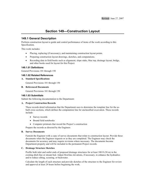
Revised: June 27, 2007Section 149—Construction Layout149.1 General DescriptionPerform construction layout to guide and control performance of items of the work according to thisSpecification.This work includes:• Placing, replacing (if necessary), and maintaining construction layout points.• Preparing construction layout drawings, sketches, and computations.• Recording data in field books such as alignment, slope stake, blue top, drainage layout, bridge,and other books used for layout for this Project.149.1.01 DefinitionsGeneral Provisions 101 through 150149.1.02 Related ReferencesA. Standard SpecificationsGeneral Provisions 101 through 150B. Referenced DocumentsGeneral Provisions 101 through 150149.1.03 SubmittalsSubmit the following documentation to the Department:A. Project Construction RecordsThese records detail information that the Department uses to determine the template line for the asbuiltcross sections, which defines the computation line for unclassified excavation. These recordsinclude:• Survey records• Bound field notebooks• Computer printouts that record the Project’s constructionPrepare the records as directed by the Engineer.B. Survey DocumentsFurnish the Engineer with a copy of survey documents that relate to construction layout. Provide thesedocuments when the Engineer requests or as they are completed. The Engineer may check thedocuments for accuracy and may require revisions where necessary. The documents becomeDepartment property and will be included in the permanent Project records.C. Drainage Structure SketchesProfile both inlet and outlet ends of proposed drainage structures for at least 100 ft (30 m) in theexisting ditch line or stream bed. Adjust flowline elevations, if necessary, to enhance the hydraulicsand to reduce silting, scouring, or backwater.Calculate the length of each structure and provide sketches of the structure to the Engineer for reviewand approval at least 24 hours before beginning the work.
D. Bridge Layout SketchFurnish a layout sketch before staking on bridges. After staking, submit a revised sketch for theEngineer’s review and approval before beginning construction. Include in the layout sketch relevantstations, angles, dimensions, and redundant checks including exterior beam dimensions in each span.Also include all horizontal and vertical clearances with calculations that verify the clearances shown.Submit for the Engineer’s review and approval survey data and calculations with the layout sketch andinformation required for bent construction.Verify the Plan elevations for all bridge bearing seats on the substructure.E. Wall Layout SketchesSubmit sketches and other data verifying either that the wall will fit the final field conditions, orindicate where revisions are necessary. Submit these sketches well before the wall construction beginsso the Engineer can make any necessary structural design changes.149.2 MaterialsGeneral Provisions 101 through 150149.2.01 Delivery, Storage, and HandlingGeneral Provisions 101 through 150149.3 Construction RequirementsGeneral Provisions 101 through 150149.3.01 PersonnelFurnish personnel capable of establishing line and grade points necessary to complete the the work.Establish these points within the generally accepted surveying tolerances, and ensure that they areacceptable for the the work being performed.149.3.02 EquipmentFurnish surveying equipment, stakes, and all materials necessary to perform the the work, subject to theEngineer’s approval.149.3.03 PreparationA. General Pre-ConstructionBefore beginning construction:1. Ensure that plan dimensions, alignment, and elevations are compatible with existing fieldconditions. Make adjustments where necessary.2. Ensure alignment tie-ins by coordinating construction layout with that of other Contractors whosework abuts any portion of the work. All adjustments are subject to the Engineer’s approval.B. Widening and ReconstructionBefore beginning construction where existing pavement is to be retained either for widening or forreconstruction:1. Take three-point levels of the pavement throughout the length to be retained.Normally, the three-point levels will be required at 50 ft (15 m) intervals. However, the Engineermay adjust these intervals according to existing field conditions.2. From the three-point levels, prepare a graphic grade plot that “best fits” the existing pavement tominimize the leveling requirements (if any) of the existing roadway. Cross slopes may be variedwithin the ranges shown on the Plans or adjusted by the Engineer to produce the “best fit.”3. On passing lane or widening Projects where existing pavement is not to be overlaid:a. Profile and plot the outside edge of the existing pavement to obtain a smooth profile grade.b. Transfer this grade to the new edge of paving using the proper cross slope.
4. Furnish data to the Engineer for approval before beginning widening and reconstruction.5. On widening, reconstruction, or passing lane projects, obtain the Engineer’s approval of the “bestfit” profile. Ensure that grade stakes are set to control the construction of any required wideningbased upon the “best fit” profile and cross slope. Construct proposed widening flush with theexisting edge of paving. Provide positive drainage in all cases.C. Existing Bridge Widening or ModificationTo widen or modify existing bridges, do the following before ordering materials or beginningconstruction:1. Verify existing elevations and dimensions as well as confirm or determine required new capelevations.2. Profile the removal line and cross section the existing deck.3. Use this profile information to determine a “best fit” finished grade for the widened portion.4. Compute the new cap elevations based on this “best fit” information.5. Furnish survey data, layout sketch, and calculations to the Engineer for approval.D. Retaining Wall Construction LayoutSet stakes, take necessary cross sections, and perform necessary calculations at each wall beforebeginning wall construction to ensure that the geometric design of the retaining wall conforms toactual conditions.149.3.04 FabricationGeneral Provisions 101 through 150149.3.05 ConstructionA. Verify Plan ElevationsVerify plan elevations for all bridge bearing seats on the substructure.B. Verify Bent LayoutAfter bent construction has begun, verify bent layout at each major phase of the construction to ensurethat the bent is properly positioned in relation to adjacent bents.C. Establish the CenterlineEstablish the centerline as follows:1. Establish or reestablish the centerline from the monuments and/or reference points the Departmentwill provide.2. On widening or reconstruction Projects, establish the horizontal and vertical alignment of theexisting roadway and bridges.3. Modify the Plan horizontal and vertical alignment to conform to the existing alignment asnecessary.D. Verify the Accuracy of the Bench Mark(s)The Department will furnish at least one bench mark that the Contractor shall preserve, and ifnecessary, relocate as follows:1. Verify the accuracy of the bench mark(s) and report discrepancies to the Engineer.2. Establish additional benchmarks needed for construction.3. Maintain the bench marks for necessary Department checks.E. Flag In-Place Survey Control MonumentsFlag and protect in-place survey control monuments and reference points, including Right-of-Way/property line intersections, as follows:1. Pay for and replace destroyed or disturbed stakes or monuments.
2. When included as Pay Items, stake Right-of-Way markers.F. Line, Grades, and StakesSet other line and grade stakes needed to construct the job, including stakes needed to relocate utilitiesand restake flattened slopes, minor grade or alignment changes, and other incidentals.G. Stake Centerline Control AlignmentsStake centerline control alignments shown on the Plans or adjusted as described above when theDepartment needs accurate measurement of quantities for payment. Stake these control alignments asfollows:1. Stake the alignments to an accuracy of 1:5000.2. Stake the alignments just before the Department takes aerial photography or field cross sectionsfor both original and final cross sections.3. Provide the Department with elevations of positions staked for the Department’s quantitymeasurements. Ensure that these elevations are of third order accuracy, or better. Determine themusing the differential leveling method.4. Take intermediate cross sections required because of stage construction, detours, or other reasons.H. Provide Graphic SketchesPrepare and use graphic sketches of superelevation runout on curves on multi-lane roadways and oftie-ins of ramps to mainline on freeways and expressways to help provide positive drainage, adequatesuperelevation, and a pleasing appearance. Prepare and use similar sketches for street or roadwayintersections.I. Maintain the StakesAfter construction has begun in any segment of the Project, maintain the stakes that identifyconstruction station numbers and locations as follows:1. Ensure that stakes are placed at intervals not to exceed 200 ft (60 m) and use even, 100 ft (30 m)stations.Mark and flag stakes so that they are visible to <strong>DOT</strong> Project personnel in that segment of theProject until construction is complete.If the project utilizes GPS controlled equipment, stakes are to be placed every 300 ft (91 m) onEnglish projects and 100 m (310 ft) on metric projects. Even, 100 ft (30m) or 100 m (310 ft)stations shall be used.2. During grading activities in fills or cuts over 20 ft (6 m), extend slope stakes up or down theslopes in intervals of 10 ft (3 m) or less to achieve an accurate cross section.J. Traffic MarkingsWhen traffic markings are to be placed by either the Contractor or others, furnish the layout and cleanand preline the surface to allow the placement of permanent pavement markings on the Project.When traffic markings are not included in the Project plans, the Department will provide striping plansand/or standard drawings for the Contractor’s use.K. Provide Bridge Construction LayoutProvide alignment control, grade control, and calculations to set these controls for bridge construction.For new bridges, the Department will furnish the necessary input data forms for the Department’s“Bridge Geometry” computer program upon the Contractor’s request. The Department will process thedata to help the Contractor obtain finished deck elevations.Data processing is available only as an alternate service to determine elevations. If this service iselected for use, prepare the input data and the Department will furnish the output data. The followinglimitations apply:• The Department will not assume liability for the accuracy of either input or output data.
• The Department will limit this service to two programs per bridge.• This service is not available for existing bridges that are to be widened. Finished deckelevations for bridges that are to be widened will not be furnished.149.3.06 Quality AcceptanceThe Engineer’s acceptance of all or any part of the Contractor’s layout shall not relieve the Contractor ofresponsibility to secure proper dimensions for the completed work. Correct at the Contractor’s expensework incorrectly located due to layout error.149.3.07 Contractor Warranty and MaintenanceGeneral Provisions 101 through 150149.4 MeasurementThis item is not measured for payment.149.4.01 LimitsGeneral Provisions 101 through 150149.5 PaymentThis work is not paid for separately. The costs for performing layout work as described in this Specificationare included in the bid for the items of work to which the layout is incidental.Any unnecessary work, overruns, costs, etc., resulting from inaccurate data submitted by the Contractorwill be deducted from Contractor payments.149.5.01 AdjustmentsGeneral Provisions 101 through 150