Distributed Fair Transmit Power Adjustment for Vehicular Ad Hoc ...
Distributed Fair Transmit Power Adjustment for Vehicular Ad Hoc ...
Distributed Fair Transmit Power Adjustment for Vehicular Ad Hoc ...

You also want an ePaper? Increase the reach of your titles
YUMPU automatically turns print PDFs into web optimized ePapers that Google loves.
<strong>Distributed</strong> <strong>Fair</strong> <strong>Transmit</strong> <strong>Power</strong> <strong><strong>Ad</strong>justment</strong> <strong>for</strong><strong>Vehicular</strong> <strong>Ad</strong> <strong>Hoc</strong> NetworksMarc Torrent-MorenoInstitute of TelematicsUniversity of KarlsruheGermanytorrent@tm.uni-karlsruhe.dePaolo SantiIstituto di In<strong>for</strong>maticae Telematica del CNRPisa, Italypaolo.santi@iit.cnr.itHannes HartensteinInstitute of TelematicsUniversity of KarlsruheGermanyhartenstein@rz.uni-karlsruhe.deAbstract— Improving the safety of drivers and passengers bywirelessly exchanging in<strong>for</strong>mation between vehicles represents amajor driving <strong>for</strong>ce <strong>for</strong> the design of vehicular ad hoc networks.In a heavy loaded 802.11-based network, however, safety-relatedpackets might collide frequently and cannot be decoded by areceiver, thus they might not be effective in increasing the safetylevel on the roads. In this paper, we propose to use transmit powercontrol in order to reduce packet collisions, while taking intoaccount the major design goal of vehicular ad hoc networks, i.e.increasing safety. While previous work has addressed the issue ofpower control primarily <strong>for</strong> optimizing network capacity and/orconnectivity, the optimization criterion <strong>for</strong> improving safety hasto be built upon the concept of fairness: a higher transmitpower of a sender should not be selected at the expense ofpreventing other vehicles to send/receive their required amountof safety in<strong>for</strong>mation. In this paper, we propose a fully distributedand localized algorithm called D-FPAV (<strong>Distributed</strong> <strong>Fair</strong> <strong>Power</strong><strong><strong>Ad</strong>justment</strong> <strong>for</strong> <strong>Vehicular</strong> networks) <strong>for</strong> adaptive transmit poweradjustment which is <strong>for</strong>mally proven to achieve max-min fairness.Furthermore, we investigate the effectiveness and robustnessof D-FPAV through extensive simulations based on a realistichighway scenario and different radio propagation models.I. INTRODUCTIONThe number of fatalities on public roads is a main concern<strong>for</strong> both public opinion and country’s governments. Severalinitiatives [1] have been started with the objective of significantlydecreasing both the number of accidents and theirresulting damage. These ef<strong>for</strong>ts do not only consider a betterconsciousness of drivers and an adequate road system, butalso the use of new technologies capable of assisting driversin order to improve safety conditions.Among the new technologies considered, vehicular ad hocnetworks (VANETs) play an important role, since the useof wireless communications offer the beneficial capability ofdirectly exchanging safety-related in<strong>for</strong>mation between vehicles.Various ef<strong>for</strong>ts (projects such as VII [2], C2CCC [3],InternetITS [4], etc., and standard bodies such as IEEE [5])are currently developing a technology that combines 802.11-based wireless communications with on-board sensors (e.g.,GPS, speedometers) in order to improve the driver’s awarenessof the surrounding environment, making available in<strong>for</strong>mationwhich he/she or other on-board sensors (e.g., radar) might notbe able to ‘see’.The exchange of safety-related in<strong>for</strong>mation comes into twoflavors: i) by detecting potentially dangerous situations throughthe periodic exchange of status in<strong>for</strong>mation (i.e., broadcastbeacons containing position, speed and so on) between allvehicles in the surrounding, and ii) by rapidly disseminatinghazard warnings in case of an emergency (event-driven messages).In this context, a major challenge is related to resourceallocation among the network participants: when VANETswill be fully deployed, medium to high traffic densities willresult in heavy-load channel conditions. In such situations(that are critical from the safety point of view), given thebroadcast nature of the exchanged in<strong>for</strong>mation, a high numberof packet collisions is expected. Thus, the minimum amountof required data needed to provide adequate safety-level froman in<strong>for</strong>mation point of view might not be reached.A possible way of mitigating this problem is to introducestrategies to control the channel load that explicitly take intoaccount the major goal of VANETs, i.e. increasing the safetyconditions on the road.In this paper, we propose a fully distributed strategy tocontrol the channel load based on adjusting the nodes’ transmitpower in order to prevent packet collisions that couldexcessively degrade the safety-related in<strong>for</strong>mation exchange.Our technique is built upon the concept of fairness, whichwe believe is fundamental in order to achieve VANETs’ finalgoal of increasing safety. As we thoroughly discuss in the nextsection, previously proposed power control approaches aimedat optimizing network capacity and/or connectivity do not suitVANETs’ characteristics. The fundamental observation is that,to make safety applications capable of detecting an unsafesituation and taking the right decisions to avoid a danger incase of emergency, it is very important that every vehicle has agood estimation of the state of all vehicles (with no exception)in its closer surrounding. In other words, if a vehicle is notassigned a fair portion of the resources, it can not announceitself to its closer neighbors, and becomes a danger itself.Thus, the available channel capacity must be shared amongnodes in a fair way.The fully distributed strategy introduced in this paper, calledD-FPAV (<strong>Distributed</strong> <strong>Fair</strong> <strong>Power</strong> <strong><strong>Ad</strong>justment</strong> <strong>for</strong> <strong>Vehicular</strong>Networks), is explicitly designed taking VANETs characteristicsinto account, and it is <strong>for</strong>mally proven to achievefairness, and to balance the relevance between beacon and
event-driven messages. The effectiveness of D-FPAV has beenverified through ns-2-based simulations with realistic highwaytraffic patterns and various radio propagation models. Theresults show that the use of D-FPAV significantly increases theprobability of receiving safety messages in case of emergencycompared to the case of no power control.The remainder of this paper is organized as follows. InSec. II, we discuss the motivations to study the problemat hand. Sec. III presents the most relevant work related tothe discussed issue. In Sec. IV, we introduce the D-FPAVdistributed algorithm <strong>for</strong> computing a provably fair powerassignment. Sec. V presents the results of the simulation studyper<strong>for</strong>med to assess the effectiveness of our proposed powercontrol strategy. Finally, Sec. VI concludes the paper.II. RATIONALEA. Assumptions and ObservationsIn accordance with the FCC ruling report [6] we assume thatthe lower layer technology used in VANETs will be a variantof IEEE 802.11a, now IEEE 802.11p [7], and there will beone 10 MHz control channel primarily <strong>for</strong> the exchange ofsafety-related messages. The <strong>Distributed</strong> Coordination Function(DCF), i.e., the IEEE 802.11 basic access mechanism, is atotally asynchronous approach. DCF is known <strong>for</strong> its inabilityto efficiently manage the medium resources, especially in caseof broadcast messages. A 10 MHz channel only offers half thedata rates of 802.11a, and lower rates are preferred because oftheir robustness to noise and interference [8]. Finally, we canexpect safety-related messages to be relatively large due to thesecurity overhead: recent studies [9] report numbers between250 and 800 Bytes <strong>for</strong> the message size.With a configuration as described above, [10] presents asimulation work showing the severe impact of the well-knownhidden terminal problem due to the resulting packet collisionsin broadcast scenarios.In such challenging conditions communication protocolsshould aim to satisfy safety applications requirements or, incommunication terms, keep packet collisions in the vehiclesurroundings low. As outlined in the previous section, safetyapplications will not only transmit periodic messages in thecontrol channel, but also event-driven ones. There<strong>for</strong>e, a keyaspect <strong>for</strong> the design of appropriate communication protocolsis to clarify what type of messages is more important dependingon the distance to the sender. The purpose and relevanceof both types of messages are described in the following.Periodic messages can be seen as preventive messages interms of safety. They convey in<strong>for</strong>mation about the state of thesending vehicle, i.e., position, direction, speed, etc., and possiblyalso aggregated data regarding the state of its neighbors.It is reasonable to assume that these periodic messages (alsocalled beacons in the following) will be sent in a broadcastfashion since the messages’ content can be beneficial <strong>for</strong>all vehicles around. Note that the existence of a beaconingmechanism can be fundamental also to implement non-safetyapplications (e.g., traffic monitoring), or protocols (e.g., geocasting).The main goal of beaconing is to improve driverawareness of the surrounding environment. We remark thateven though the reception of a beacon is somehow ‘expected’,the in<strong>for</strong>mation contained can be of critical importance in closedistances to the sender since it can make possible to detectan unsafe road situation (i.e., proximity of crossing vehiclesat an intersection). This argumentation line is followed inother studies, e.g. [11], to suggest that the beaconing messagegeneration rate should be in the order of several packets persecond to provide the safety system with accurate enoughin<strong>for</strong>mation from the close surrounding.Event-driven messages, instead, are the result of the detectionof a hazard, e.g., hard braking from a car, an emergencyvehicle driving at high speed, etc. Hence, the in<strong>for</strong>mation theyconvey is of primary importance also <strong>for</strong> relatively farthernodes, and they should be propagated as quickly as possiblealong the road. The purpose of event-driven messages isto enable drivers to undertake adequate countermeasures incase of an emergency: several accidents could be avoided ifdrivers would be made aware of the peril just few seconds (oreven a fraction of a second) be<strong>for</strong>e they can actually see it.B. What is needed?Fully deployed VANETs will encounter situations where thetechnology limitations described above become a challenge.Un<strong>for</strong>tunately, these situations are often critical in terms ofsafety. For instance, consider scenarios with medium to highvehicle densities and relatively high speeds, such as highwaysnear the entrance of big cities or a temporary working area.Due to a large number of vehicles sharing the medium, it isnot clear whether the channel capacity is sufficient to supportthe data load generated by beaconing while at the same timeleaving enough available bandwidth <strong>for</strong> event-driven safetymessages.In the following we outline the rationale behind our strategyin linking safety and fairness as a sequence of reasonings thateventually define the requirements <strong>for</strong> fair power adjustment<strong>for</strong> vehicular networks.1. Relevance of safety messages. Event-driven messagesshould be able to access the control channel with short delay,and they should have low probability of collision even whentargeting large areas, i.e., when being transmitted with highpower. Beacons, on the other hand, show a high relevance inthe close neighborhood of the sender, but they are less relevantat higher distances (in analogy to the standard ‘safety distance’of vehicles). Thus, a resource allocation strategy is needed thatachieves a clear prioritization, or balance, among the messagesaccording to their relevance <strong>for</strong> safety.2. Balancing event-driven messages and beacons. Takinginto account the relevance <strong>for</strong> safety, it is our belief that theamount of load resulting from beaconing should be limited: itis desirable to i) avoid a high number of beacon’s collisions,and ii) leave some available bandwidth to handle unexpectedemergency situations with the necessary reliability. Thus, weneed to design a ‘congestion control mechanism’ which is ableto keep the periodic messages’ load under a specific maximumvalue at all the nodes of the network. This threshold, called
MaxBeaconingLoad (MBL) in the following, represents a limitwhere safety protocols can achieve a reasonable per<strong>for</strong>manceat a specified data rate (or modulation).3. Keeping the beaconing load below MBL. We propose toadjust the transmission power used <strong>for</strong> beaconing messagesin order to keep the load in the medium below MBL. Thisway, by using the design proposed in this paper, the MBLthreshold can be seen as a handle to fine-tune the level ofprioritization between beacon and event-driven messages: byincreasing the MBL, the beaconing activity is assigned a largerportion of the available bandwidth, and a relatively “lower”priority (although still higher than that of beacons) is implicitlyassigned to event-driven messages. In this paper, we assumethat the MBL threshold is assigned a fixed level (set to halfof the available bandwidth in Section V), and we leave thedesign of a strategy <strong>for</strong> dynamically setting the MBL value,e.g., depending on traffic conditions, as future work.We are aware that be<strong>for</strong>e decreasing the transmission powerof beacons other strategies should be implemented, such asrealizing an admission control mechanism to drop all nonsafetyrelated packets be<strong>for</strong>e being sent to the control channel,or dynamically adjusting the packet generation rate. Nevertheless,there will be many situations where decreasing thetransmission range of certain nodes on top of that is necessary(e.g., fast moving medium density traffic conditions). Althoughtransmit power control has been a deeply studied subject inthe mobile networks field already (see related work in SectionIII), vehicular environments present new challenges. Mostof previous studies addressing power control try to ensureconnectivity and/or optimize capacity of ad hoc networks.However, the primary goal of transmit power control whenapplied to VANETs is not to optimize data transport capacity<strong>for</strong> several ongoing point-to-point communications, or to builda connected network topology (see the toy examples depictedin Fig. 1), but instead to improve as much as possible thedriver’s awareness of a vehicle’s surroundings.4. The elements of fairness. To limit the beaconing loadoffered to the medium at all points in the network below thespecific common MBL, vehicles should restrict their beacons’transmission power. From an individual safety point of view(e.g., looking at the kinetic energy of vehicles) a higherrange of awareness is preferable. From a system perspectivethe vehicle with the minimum transmission power can beconsidered a safety hazard <strong>for</strong> the other cars (or vice versa).As already observed in the introduction, it is very importantthat every node (vehicle) has a good estimation of the stateof all vehicles (with no exception) in its closer surrounding.Thus, essentially, a max-min fairness concept is required. Onemight argue that due to different velocities of vehicles – orgeneral due to different ‘states’ of the vehicles – the vehiclesshould send beacons with transmission power related to theirvelocity or status. In this case the transmission power shouldbe restricted by the same ratio to satisfy MBL.5. <strong>Fair</strong>ness with low complexity. <strong>Ad</strong>ditionally, vehicularnetworks are composed of highly mobile nodes. There<strong>for</strong>e, thepower adjustment mechanism cannot be based on a strategyCloud ACloud BVehicle C(a) If nodes from Cloud B would try to be connected with faraway Vehicle C, they can create high interferences disturbingin<strong>for</strong>mation exchange among vehicles inside Cloud A.Cloud A(b) If nodes <strong>for</strong>ming Cloud A would try to optimize capacitythey would adjust their transmit power to reach only theclosest car. In this case, they would not have direct awarenessof the next vehicle in the same lane even though it is veryclose.Fig. 1. Road situations showing drawbacks of unfair power control inVANETs.which converges to stable power settings over a relatively longperiod of time; instead, it must be able to quickly react tochanges of nodes’ requirements and locations.III. RELATED WORKThis paper is the continuation of our work [12], where weintroduced the concept of fairness as a key factor <strong>for</strong> vehicularsafety communications. The paper [12] also presenteda strategy to achieve a max-min fairness power assignment(inspired by Water Filling as presented in [13]) assumingglobal knowledge, i.e., using a centralized algorithm, whichis clearly impractical in a vehicular environment. The contributionsof the present paper with respect to [12] are: i) a fullydistributed scheme to achieve the fair power assignment, whichis <strong>for</strong>mally proven to achieve fairness, ii) a strategy to estimatethe state of a vehicle’s surrounding, needed <strong>for</strong> the properfunctionality of the power assignment technique, and iii)extensive simulations, with three different radio propagationmodels, that show how the proposed strategies accomplishthe goals presented in the previous section in real highwayscenarios.Apart from [12], the previous work related to this papercan be classified in two main categories. The first one istopology control in ad hoc networks. Although it has beenan intensively studied field <strong>for</strong> many years, VANETs’ specificparadigms make all these analyses or proposed algorithms notvalid to satisfy their requirements. Most of these studies dealwith point-to-point communications and try to find a path todestination with a local or distributed approach while maximizingthe system overall capacity and/or energy consumption([14] and [15]). As outlined in Sec. II, neither overall capacitynor energy efficiency are the main driving factors in VANETs.Maybe, the study in this area which is most related to our workis [16], which proposes an adaptive algorithm to maximize1-hop broadcast coverage. However, this study addresses staticnetworks and does not consider different requirements withrespect to communication ranges, which makes their approachnot valid <strong>for</strong> VANETs.
The second area of research related to our work is theone addressing fairness to share the wireless medium. In thiscategory we can find strategies that consider only unicastcommunications and i) assign a portion of the estimated bandwidthto each flow, such as [17], or ii) provide a schedulingmechanism to achieve its fairness criteria, e.g., [18].Recently, due to the increasing attention of researchers onVANETs, some studies have tried to apply these methodologiesto vehicular environments. For example, [19] addressespower control in VANETs with the goal of producing a connectednetwork topology; or [20], which describes a schemebased on a utility fair function to share the broadcast medium.In the latter, a scheduling approach is proposed that can beperfectly valid <strong>for</strong> non-safety VANETs’ applications, however,it does not satisfy all the safety constraints presented inSec. II.IV. THE DISTRIBUTED FPAV ALGORITHMBased on the rationale outlined in Section II and on theBMMTxP (Beaconing Max-Min Tx <strong>Power</strong>) problem as givenin [12] we define the D-FPAV algorithm and <strong>for</strong>mally provethat it achieves fairness.A. The BMMTxP problem and D-FPAVHere, a short version of the problem statement and definitionspresented in [12] are reproduced, which are required toprove Theorem 1. We refer the reader to Section 3.2 of [12] <strong>for</strong>a complete explanation with the correspondent justifications.Assume a set of nodes N = {u 1 ,...,u n } is moving alonga road modeled as a line 1 of unit length, i.e. R = [0,1], andthat nodes can be modeled as points x(i) ∈ [0,1].Each of the network nodes sends a beacon with a predefinedbeaconing frequency F , using a certain transmit powerp ∈ [0,P max ].Definition 1 (<strong>Power</strong> assignment): Given a set of nodesN = {u 1 ,...,u n }, a power assignment PA is a functionthat assigns to every network node u i , with i = 1,...,n, aratio PA(i) ∈ [0,1]. The power used by node u i to send thebeacon is PA(i) · P max .Definition 2 (Carrier Sensing Range): Given a power assignmentPA and any node u i ∈ N, the carrier sensing rangeof u i under PA, denoted CS(PA,i), is defined as intersectionbetween the commonly known CS range 2 of node u i at powerPA(i) ·P max and the deployment region R. The CS range ofnode u i at maximum power is denoted CS MAX (i).Given a power assignment PA, the network load generatedby the beaconing activity under PA is defined as follows.Definition 3 (Beaconing load under PA): Given a set ofnodes N and a power assignment PA <strong>for</strong> the nodes in N,1 Modeling the road as a line is a reasonable simplification in our case sincewe assume the communication ranges of the nodes to be much larger thanthe width of the road.2 The CS (Carrier Sense) range, in ideal conditions, is the distance to whicha node’s transmissions can be sensed, or also considered as the distance towhich a node can interfere with other transmissions.u 1u 2u 3u 4u 5u 6u 7u 850mFig. 2. Node deployment used in the example of D-FPAV execution.the beaconing network load at node u i under PA is definedas:BL(PA,i) = |{u j ∈ N,j ≠ i : u i ∈ CS(PA,j)}| ,where CS(PA,j) is the carrier sensing range of node u j underpower assignment PA.We remark that the above definition of beaconing load can beeasily extended to account <strong>for</strong> beacon messages of differentsize, and <strong>for</strong> different beaconing frequencies in the network.The framework <strong>for</strong> distributed power control discussed belowcan be applied also with a more general definition of beaconingload.Definition 4: (Beaconing Max-Min Tx power Problem(BMMTxP)): Given a set of nodes N = {u 1 ,...,u n } inR = [0,1], determine a power assignment PA such that theminimum of the transmit powers used by nodes <strong>for</strong> beaconingis maximized, and the network load experienced at the nodesremains below the beaconing threshold MBL. Formally,⎧⎨⎩max PA∈PA (min ui∈N PA(i))subject toBL(PA,i) ≤ MBL ∀i ∈ {1,...,n}where PA is the set of all possible power assignments.In [12], we presented FPAV, an algorithm based on ‘waterfilling’ able to compute PA when global knowledge wasassumed. In order to facilitate reading and due to completenesswe describe the essentials of the FPAV algorithm. Fig. 3presents FPAV which works as follows: every node startswith the minimum transmit power assigned; then, all thenodes increase their transmit power simultaneously of the sameamount ǫ · P max as long as the condition on the beaconingnetwork load (MBL) is satisfied. At the end of FPAV all nodeshave increased their power the same number of steps k and endup with a power of p = (kǫ) ·P max . Note that in [12] we alsoproposed a ‘second stage’ of the FPAV algorithm in order toachieve per-node maximality. However, it is not included in thepresent study because further simulations showed a marginalgain in many cases due to the high network dynamics. In thefollowing we present a fully distributed, asynchronous, andlocalized algorithm called D-FPAV <strong>for</strong> solving BMMTxP.D-FPAV is summarized in Figure 4. A node u i is continuouslycollecting the in<strong>for</strong>mation about the status (currentposition, velocity, direction, and so on) of all the nodes withinits carrier sensing range at maximum power CS MAX (i).These are the only nodes that node u i can affect when sendingits beacon. The actual mechanism to acquire the required statein<strong>for</strong>mation is discussed in the following subsection. Basedon this in<strong>for</strong>mation, node u i makes use of FPAV to computethe maximum common value P i of the transmit power <strong>for</strong> all,
Algorithm FPAV:INPUT: a set of nodes N = {u 1 ,...,u n } in [0,1]OUTPUT: a power assignment PA which is an(ǫ · P max -approximation of an) optimal solutionto BMMTxP∀u i ∈ N, set PA(i) = 0while (BL(PA) ≤ MBL) do∀u i ∈ N, PA(i) = PA(i) + ǫend while∀u i ∈ N, PA(i) = PA(i) − ǫFig. 3. The FPAV algorithm.Algorithm D-FPAV: (algorithm <strong>for</strong> node u i )INPUT: status of all the nodes in CS MAX (i)OUTPUT: a power setting PA(i) <strong>for</strong> node u i , such thatthe resulting power assignment is an optimalsolution to BMMTxP1. Based on the status of the nodes in CS MAX (i),compute the maximum common tx power levelP i s.t. the MBL threshold is not violated at anynode in CS MAX (i)2a.Broadcast P i to all nodes in CS MAX (i)2b. Receive the messages with the power level fromnodes u j such that u i ∈ CS MAX (j); store thereceived values in P j3. Compute the final power level:PA(i) = min { P i ,min j:ui∈CS MAX(j){P j } }Fig. 4. The D-FPAV algorithm.nodes in CS MAX (i) such that the condition on the MBL is notviolated (step 1). Note that this computation is based on localin<strong>for</strong>mation only (the status of all the nodes in CS MAX (i)),and it might be infeasible (i.e., it might violate the conditionon MBL at some node) globally. To account <strong>for</strong> this, nodeu i broadcasts the computed common power level P i to allnodes in CS MAX (i) (step 2a). In the meanwhile, node u ireceives the same in<strong>for</strong>mation from the nodes u j such thatu i ∈ CS MAX (j) (step 2b). After having received the powerlevels computed by the nodes in its vicinity, node u i cancompute the final transmit power level, which is set to theminimum among the value P i computed by the node itselfand the values received from nodes in the vicinity (step 4).Setting the final power level to the minimum possible level isnecessary in order to guarantee the feasibility of the computedpower assignment (see theorem below).Theorem 1: Assume the CS ranges of the nodes are symmetric,i.e. u i ∈ CS MAX (j) ⇔ u j ∈ CS MAX (i). Then,algorithm D-FPAV computes an optimal solution to BMMTxP.Proof: First, we have to show that the power assignmentcomputed by D-FPAV is a feasible solution to BMMTxP.Assume the contrary, i.e. assume there exists node u i suchthat BL(PA,i) > MBL, where PA is the power assignmentcomputed by D-FPAV. This means that node u i has too manyinterferers, all of which are located in CS MAX (i) (assumingsymmetric CS ranges). Let u j ,...,u j+h , <strong>for</strong> some h > 0,be these interferers, and let PA i be the power assignmentcomputed by node u i <strong>for</strong> all the nodes in CS MAX (i). Instep 1 of D-FPAV, u i computes an optimal solution PA ito BMMTxP restricted to CS MAX (i). Assuming symmetricCS ranges, this solution includes a power setting <strong>for</strong> theinterferers u j ,...,u j+h , and this power setting is such thatBL(PA i ,i) ≤ MBL. At step 2 of D-FPAV, the power settingPA i is broadcasted to all the nodes in CS MAX (i), whichincludes all the interferers u j ,...,u j+h . Hence, each of theinterferers receives from node u i a power setting PA i suchthat the condition on the beaconing load is not violated atnode u i . Since the final power setting of the interferers is atmost PA i (this follows from the minimum operation executedat step 3 of D-FPAV), and assuming a monotonic CS range,we have that the beaconing load at node u i cannot exceed theMBL threshold – contradiction. This proves that the powerassignment computed by D-FPAV is a feasible solution toBMMTxP.Let us now prove that the computed power assignment isoptimal. Let PA be the power assignment computed byD-FPAV, and let p min be the minimum of the node powerlevels in PA. Assume PA is not optimal, i.e. that thereexists another feasible solution PA ′ to BMMTxP such thatthe minimum of the node power levels in PA ′ is p ′ > p min .Without loss of generality, assume that PA ′ sets the powerlevel of all the nodes to p ′ . Since PA ′ is feasible, we havethat BL(PA ′ ,i) ≤ MBL ∀i ∈ 1,...,n. Hence, every nodeu i in the network computes a power setting P i ≥ p ′ at step 1 ofD-FPAV. Consequently, the final power setting of every nodein the network as computed by D-FPAV is at least p ′ > p min ,which contradicts our initial assumption. It follows that thesolution computed by D-FPAV is optimal.Theorem 2: Algorithm D-FPAV has O(n) message complexity.The straight<strong>for</strong>ward proof of the theorem is omitted.Let us use the scenario of Figure 2 to present D-FPAVexecution with a toy example. We have eight cars, denotedu 1 ,...,u 8 , which are placed on a 1km long road, with relativedistance varying from 50m to 200m. For the sake of clarity,we assume that the carrier sensing range can be representedas a segment centered at the transmitting node, and that themaximum CS range is initially 400m. We also assume thatall nodes send beacons of the same size with equal frequency,being the maximum beaconing load MBL such that any nodecan be in the CS range of at most two other nodes.We summarize D-FPAV execution with the matrix reportedin Table I, where the row corresponding to node u i reportsthe values of the transmit power (actually, what is reported in
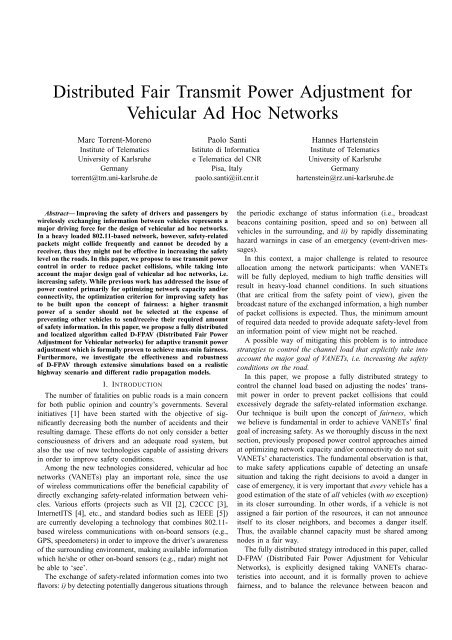
u 1 u 2 u 3 u 4 u 5 u 6 u 7 u 8u 1 150 150 150 150 150u 2 50 50 50 50 50 50u 3 50 50 50 50 50 50 50u 4 50 50 50 50 50 50 50u 5 50 50 50 50 50 50 50 50u 6 50 50 50 50 50 50 50u 7 50 50 50 50 50 50u 8 150 150 150 150TABLE ISUMMARIZATION OF D-FPAV EXECUTION. ENTRIES REPRESENT INMETERS THE MAXIMUM ALLOWED VALUE OF THE CS RANGE PER NODE.the entries is the value of the CS range, which is defined by acorrespondent transmit power level) as computed by node u i<strong>for</strong> all the nodes within its maximum CS range. For instance,the first row of the matrix represents the fact that node u 1computes maximum allowed CS range equal to 150m <strong>for</strong> allthe nodes within its maximum CS range, i.e. nodes u 1 ,...,u 5 .On the other hand, columns represent all the values of theallowed CS range that a node receives from the nodes withinits CS range. For instance, the first column represents thefact that node u 1 receives a power setting <strong>for</strong> itself by nodesu 2 ,...,u 5 . Then, the final power setting <strong>for</strong> every node inthe network as computed by D-FPAV corresponds to takingthe minimum over the values in its column. In our example,every node will end up D-FPAV execution setting the transmitpower to a value such that the corresponding CS range is 50m.B. Estimation of status in<strong>for</strong>mationLet us now discuss how node u i can collect the statusin<strong>for</strong>mation of all its surrounding nodes in order to computethe appropriate power level.The only option to acquire status in<strong>for</strong>mation from allnodes in CS MAX (i), which includes nodes located outsideof the transmission range, is making use of a strategy whereintermediate nodes re-transmit the status of their neighbors.Clearly, in a dynamic scenario only an estimation of theactual status in<strong>for</strong>mation will be available at the time D-FPAVhas to adjust the transmission power of a beacon, i.e., thelast received in<strong>for</strong>mation from neighboring nodes. There<strong>for</strong>e,the accuracy of D-FPAV will depend on the frequency thateach node transmits both its own and its neighbors statusin<strong>for</strong>mation. Furthermore, our algorithm requires the P i valuesfrom all nodes in CS MAX (i).We propose that each node aggregates the P i values withthe status in<strong>for</strong>mation of the corresponding nodes insideCS MAX (i) and then, to improve efficiency, piggyback thisaggregated in<strong>for</strong>mation in beacon messages.Now, decisions must be done with respect to what fractionof beacons should be piggybacked, and which transmit powershould be used to send beacons containing this additional in<strong>for</strong>mation.In making these choices there is a trade off betweenamount of load offered to the channel and accuracy of theneighbors status in<strong>for</strong>mation available at the nodes. Utilizing ahigher transmission power and piggybacking a higher numberof beacons could provide a higher accuracy of the requiredin<strong>for</strong>mation and, there<strong>for</strong>e, of D-FPAV per<strong>for</strong>mance. However,this additional amount of load have to be, in turn, controlleddue to D-FPAV’s purpose of limiting the load on the channel.In order to select the better option, we have per<strong>for</strong>med apreliminary set of ns-2 based simulations, using five differentconfigurations:1) piggyback the aggregated status in<strong>for</strong>mation to eachbeacon and transmit it with power PA(i) (the transmitpower value as computed by D-FPAV).2) piggyback the in<strong>for</strong>mation every 5 beacons and usepower P max <strong>for</strong> sending the augmented beacon.3) piggyback the in<strong>for</strong>mation every 5 beacons and usepower PA(i) <strong>for</strong> sending the augmented beacon.4) piggyback the in<strong>for</strong>mation every 10 beacons and usepower P max <strong>for</strong> sending the augmented beacon.5) piggyback the in<strong>for</strong>mation every 10 beacons and usepower PA(i) <strong>for</strong> sending the augmented beacon.We considered that sending piggybacked beacons with a lowerfrequency than one every 10 beacons would cause D-FPAV todeal with too outdated in<strong>for</strong>mation.Simulation results, which are not shown due to lack ofspace, showed that option 5) (send the status every 10 beaconswith power PA(i)) offers the best tradeoff between updatedstatus in<strong>for</strong>mation and additional overhead on the medium. Forthis reason, in the following we assume that neighbor statusin<strong>for</strong>mation is updated according to strategy 5) above.A. Simulation SetupV. SIMULATION STUDYThe version of the network simulator utilized in our experimentsis ns-2.28 [21], although several improvements havebeen included to the downloadable version. First, several bugshave been fixed in the MAC layer [22]. Second, the physicallayer has been adjusted to the IEEE 802.11p technology [7]with the values provided in [10]. Third, the Nakagami radiopropagation model, whose parameters were adjusted to matchactual measurements reported in [23], has been used.In order to have a realistic scenario with a dynamic networktopology, we employed the publicly available German highwaypatterns described in [24]. The chosen set <strong>for</strong> our evaluationis the most critical <strong>for</strong> safety: fast moving, ‘heavy’ traffic.In particular, we considered a 12km long road with hightraffic density, where vehicles travel at an average speed of121.86km/h. This straight portion of highway is composed of6 lanes, 3 in each direction, with an average vehicle densityof 11 vehicles per kilometer and lane (see a screenshot of thevisualization tool HWGui [24] in Fig. 5).There are several other parameters that have to be configuredto run reasonable simulation scenarios. We selected apacket generation rate <strong>for</strong> beacons of 10packets/s, which isconsidered an acceptable value to provide accurate enoughin<strong>for</strong>mation to the safety system [11]. The packet size of allbeacons have been fixed to 500Bytes, which is approximatelyin the middle of the interval of reasonable packet sizes in
Probability of Message Reception10.80.60.40.20Two-Ray-GroundShadowingNakagamiFig. 5. Screenshot of the utilized scenario, which consists in a 12km longbi-directional highway with 3 lanes per direction.VANETs as reported in the security study [9]. In [8], itis shown that BPSK modulation schemes of OFDM-basedwireless LAN technologies, such as 802.11p, are advisable dueto their robustness. We have chosen a 3Mbps data rate due toits lowest SNR requirement, namely 4dB. Concerning D-FPAVimplementation, we have fixed the MBL to 1.5Mbps (at mosthalf of the channel capacity can be used <strong>for</strong> beaconing) andeach neighbor entry to 15Bytes (corresponding to VehicleIDand position). Finally, in order to see the effect of D-FPAV ondifferent safety requirements, we have considered two intendedcommunication ranges at maximum power, namely 250m and500m. With these configuration parameters, the maximum CSrange is 397m and 664m, respectively.In order to see the effect that different radio propagationmodels have on D-FPAV per<strong>for</strong>mance, we have consideredthree well-known models as a representative set: the deterministicTwo-Ray Ground (TRG) model, and the probabilisticLog-Normal Shadowing (LNS) and Nakagami (Nak) models.The TRG model, as implemented in ns-2.28, provides a diskrangemodel, i.e., a fix communication and carrier sense ranges<strong>for</strong> a defined Tx<strong>Power</strong>. The log-normal shadowing model, alsofrom ns-2.28, has been configured with a path loss exponentβ = 2 and a shadowing deviation σ dB = 6dB according to anoutdoor environment. The Nakagami model was built in [23]and configured as in [10], with a fading intensity m = 3 <strong>for</strong>distances up to 50m, m = 1.5 <strong>for</strong> distances between 50m and150m, and m = 1 <strong>for</strong> distances larger than 150m.We remark the importance of per<strong>for</strong>ming simulations withpropagation models that include realistic (shadowing and fading)effects, in order to estimate the per<strong>for</strong>mance results with ahigher degree of accuracy. In Fig. 6, we report the probabilityof correctly receiving a message in absence of interferenceas a function of distance, <strong>for</strong> the three propagation modelsconsidered in our simulations.Note that the term communication range (CR) does onlyhold with TRG due to its deterministic approach. In the followingthough, we will make use of CR = 250m as equivalentto Tx<strong>Power</strong> = -37.2dB and CR = 500m as equivalent toTx<strong>Power</strong> = -31.1dB <strong>for</strong> conveniency. The main configurationparameters used in our simulations are reported in Table II.For statistical significance, we run 50 times each possible0 200 400 600 800 1000Distance [m]Fig. 6. Probability of correctly receiving a message as a function ofdistance <strong>for</strong> the simulated radio propagation models, with CR = 500m(Tx<strong>Power</strong> = -31.1dB).TABLE IICONFIGURATION PARAMETERS802.11p data rate 3MbpsPackets generation rate 10 packets/sPacket size500 bytesIntended comm. range 250m, 500mRadio propagation models TRG, Nak, LNSNumber of lanes3 × directionVehicle density11 cars/(km· lane)D-FPAVOn, OffD-FPAV MBL1.5Mbpsconfiguration with different random seeds during 10 secondsof real time. The average and the confidence interval (with95% confidence level) of the studied metrics are presented inthe following section.In the highway scenario described above, we have configuredall vehicles to send beacon messages with the prescribedrate, and one specific node, which is located approximatelyin the center of the 12km long road, to send event-drivenmessages. Event-driven messages are sent with the same rateas beacons (10 packets/s) and at maximum transmit power. Inorder to evaluate D-FPAV per<strong>for</strong>mance we per<strong>for</strong>m two typesof simulation, D-FPAV-Off and D-FPAV-On. In D-FPAV-Offsimulations, beacons are sent at maximum power since nopower control is applied. On the other hand, <strong>for</strong> D-FPAV-On,beacons are sent at the transmit power computed by D-FPAV.Note that when applying D-FPAV, only the beacon’s Tx<strong>Power</strong>can be decreased.The two metrics analyzed to evaluate D-FPAV’s per<strong>for</strong>manceare: i) the average Channel Busy Time ratio (CBT),and ii) the probability of successful reception of a (beaconand event-driven) message with respect to the distance. CBTrepresents the fraction of time that a wireless interface sensesthe channel to be busy, i.e., a possible transmission (withenergy higher than its CS threshold) is on the medium. TheCBT metric is used to corroborate the claim that D-FPAVreduces the load on the channel uni<strong>for</strong>mly in the network,i.e., it achieves fairness. The probability of reception is used
to assess D-FPAV’s effectiveness in achieving an appropriateprioritization of safety-related messages (design goal stated inSec. II-B), which is obtained by increasing the probability ofcorrectly receiving event-driven messages while at the sametime not decreasing too much the probability of correctlyreceiving beacons close to the sender.Due to space restrictions, only figures corresponding toCR = 500m are provided and will be used <strong>for</strong> the results’discussions. However, the differences with CR = 250m willbe remarked when appropriate.B. Simulation ResultsFigures 7, 8 and 9 depict the average CBT <strong>for</strong> all nodesin the network when CR = 500m <strong>for</strong> the different radiopropagation models. In the highway scenario, nodes with IDfrom 0 to 467 correspond to vehicles driving in one direction,and nodes with ID from 468 to 932 correspond to vehiclesdriving in the opposite direction. Note how vehicles that keepclose to the border of the highway sector <strong>for</strong> the ten simulatedseconds (IDs smaller than 60, between 450 and 550, and higherthan 900) experience lower CBT due to the border effect.The following observations are in order:a) <strong>Fair</strong>ness: If no power control is applied, nodes experienceconsiderably different values of the CBT, ranging from about0.3 to 0.6 with TRG propagation, and from about 0.3 to0.7 with LNS propagation. This means that different nodeshave different opportunities of sending and correctly receivingevent-driven messages, impairing fairness. Even worse, nodestraveling in denser areas, where the likelihood of having anaccident is higher, experience a higher CBT, which results ina longer expected delay in propagating event-driven messages.On the other hand, when D-FPAV is active all the nodes(excluding the ones on the border, which have a lower CBTvalue) have the same CBT value, i.e. the same opportunitiesof sending and correctly receiving safety messages. In otherwords, D-FPAV achieves its design goal of fairness.b) CBT reduction with D-FPAV: independently of the radiopropagation model, D-FPAV achieves considerable reductionsin the CBT value with respect to the case of no power control.For instance, in case of LNS propagation, the CBT value ofcertain nodes can be reduced from about 0.7 to about 0.3,i.e., a 57% reduction. As will be seen later in this section, thereduction of the average CBT provides the desired bandwidthresources in order to improve the event-driven messages’reception rates at all distances from the sender.c) Effects of the radio propagation model: in absolute terms,the highest CBT values are experienced with LNS propagation.See the smooth decrease with distance of the probability ofcorrectly receiving a message with LNS propagation in Fig. 6,which implies a larger area being interfered (on the average)when there is an ongoing communication. As we will seelater, this phenomenon impacts also the probability of correctlyreceiving a (beacon or event-driven) message.The same behavior with respect to CBT can be observedcase of CR = 250m, the only relevant difference being thatsmaller reductions in the CBT values when D-FPAV is usedChannel Busy Time Rate10.80.60.40.200 100 200 300 400 500 600 700 800 900 1000NodeIDD-FPAV-OffD-FPAV-OnFig. 7. Channel Busy Time of each node in the highway scenario withTwo-Ray Ground model, CR = 500 and D-FPAV-On/Off.Channel Busy Time Rate10.80.60.40.200 100 200 300 400 500 600 700 800 900 1000NodeIDD-FPAV-OffD-FPAV-OnFig. 8. Channel Busy Time of each node in the highway scenario withNakagami model, CR = 500 and D-FPAV-On/Off.Channel Busy Time Rate10.80.60.40.200 100 200 300 400 500 600 700 800 900 1000NodeIDD-FPAV-OffD-FPAV-OnFig. 9. Channel Busy Time of each node in the highway scenario withLog-Normal Shadowing model, CR = 500 and D-FPAV-On/Off.
can be observed. For instance, in case of LNS propagation,some nodes experience a reduction in the CBT value fromabout 0.5 to 0.3, a 40% reduction.Let us now consider the probability of correctly receiving a(event-driven or beacon) message as a function of distance.Figures 10, 11 and 12 report the probability of messagereception <strong>for</strong> all settings described in Section V-A.The following can be observed from the figures:a) Higher probability of receiving event-driven messages:independently of the radio propagation model, of the intendedcommunication range, and of the distance from the sender, theprobability of correctly receiving an event-driven message withD-FPAV-On is higher than in the case of no power control. Theamount of the increase in reception probability depends onthe distance from the sender, on the radio propagation model,and on the CR. In general, we can observe an intermediaterange of distances (about 100m-250m with CR = 250m, andabout 100m-600m with CR = 500m) in which the increaseof the reception probability with D-FPAV is more notable.For instance, with Nak propagation and CR = 500m, theprobability of correctly receiving an event-driven message at adistance of 400m from the sender is about 0.42 with D-FPAV,while it is only about 0.2 with no power control, correspondingto a 110% increase.b) Lower probability of receiving beacon messages: the priceto pay <strong>for</strong> having a higher probability of receiving eventdrivenmessages is a decreased probability of receiving beaconmessages. The amount of this decrease is strongly dependenton distance: when the receiver is very close to the sender(100m or less), the probability of correctly receiving thebeacon is only marginally reduced with respect to the case ofno power control. Actually, it is even increased in very closedistances to the sender (<strong>for</strong> instance, with Nak propagation,CR = 500m, and distance below 80m). After this ‘close in’distance, the probability of correctly receiving beacons issignificantly lower than in the case of no power control. Thislower beacon reception probability is due to the lower transmitpower used to transmit beacons, which is necessary to reducethe beaconing load below the MBL threshold.c) Effects of the radio propagation model: as expected, thereception probability is lower with more realistic propagationmodels such as LNS and Nak than in the case of deterministicpropagation such as TRG. For instance, the probability ofcorrectly receiving an event-driven message at 200m from thesender with CR = 250m is about 0.8 with TRG, while it isabout 0.45 with both LNS and Nak. When the CR is doubled,the reception probabilities at 200m become about 0.92 withTRG, and about 0.75 with LNS and Nak.We want to remark that the observed behavior withD-FPAV-On (higher reception probability <strong>for</strong> event-drivenmessages at all distances, and lower reception probability<strong>for</strong> beacons at medium-long distances) satisfies the safetyrelateddesign goals outlined in Sec. II-B. Beacons are repeatedfrequently, and the in<strong>for</strong>mation they convey is mostlyimportant <strong>for</strong> nodes in close distances to the sender. Hence, thelower reception probability of beacons beyond the ‘close in’Probability of Message Reception10.80.60.40.2D-FPAV-On Event-drivenD-FPAV-Off Event-drivenD-FPAV-Off BeaconD-FPAV-On Beacon00 200 400 600 800 1000Distance [m]Fig. 10. Probability of Reception over the distance with Two-Ray Groundmodel, CR=500 and D-FPAV-On/Off.Probability of Message Reception10.80.60.40.2D-FPAV-On Event-drivenD-FPAV-Off Event-drivenD-FPAV-Off BeaconD-FPAV-On Beacon00 200 400 600 800 1000Distance [m]Fig. 11. Probability of Reception over the distance with Nakagami model,CR = 500 and D-FPAV-On/Off.Probability of Message Reception10.80.60.40.2D-FPAV-On Event-drivenD-FPAV-Off Event-drivenD-FPAV-Off BeaconD-FPAV-On Beacon00 200 400 600 800 1000Distance [m]Fig. 12. Probability of Reception over the distance with Log-Normal Shadowingmodel, CR = 500 and D-FPAV-On/Off.
distance is not critical in terms of safety. On the other hand,event-driven messages require an immediate action at themoment they are issued <strong>for</strong> vehicles located at both close andfurther distances, so that accidents can be avoided. This isaccomplished by the considerably higher reception probabilityof event-driven messages with D-FPAV-On, at both close andfurther distances from the sender.VI. CONCLUSIONSIn this paper, we have addressed a major challenge inVANETs, the problem of allocating network resources amongneighboring vehicles on the road. Following the guidelinesdescribed in [12], we have classified VANETs safety-relatedmessages in event-driven and beacons, and discussed theirrelevance with respect to the distance to the sender. Motivatedby expected channel saturation conditions in high trafficscenarios, we have proposed a fully distributed strategy calledD-FPAV based on transmit power adjustment of beaconingmessages. Contrary to previous power control studies, ourstrategy is motivated by the safety requirements of VANETs’applications: fairness is the metric to be achieved, coupled witha balance of safety-related messages. We have <strong>for</strong>mally definedthe problem and proven that the D-FPAV algorithm achievesfairness. We have conducted a per<strong>for</strong>mance evaluation basedon ns-2 simulation with a realistic – fast moving ‘heavy’ trafficdensity – highway scenario, and considering different radiopropagation models (both deterministic and probabilistic). Theobtained results show that D-FPAV achieves i) strict fairnessin terms of channel busy time sensed by every node in thehighway and ii) a priorization of event-driven messages overbeacons. The reception probability of event-driven messagescan be increased with D-FPAV at all distances to the sender,while the reception probability of beacons is only marginallyreduced <strong>for</strong> ‘close in’ distances, i.e., where their in<strong>for</strong>mationis most relevant.In terms of future work, we are interested in determiningthe effect of changing the MBL value on the D-FPAV per<strong>for</strong>mance,i.e., fine-tuning the relative priority of event-drivenwith respect to beacon messages. In turn, we intend to evaluatehow the increase in event-driven message reception probabilitytranslates into a faster propagation of hazard warnings on theroad.ACKNOWLEDGMENTMarc Torrent-Moreno acknowledges the support of theGerman Ministry of Education and Research (BMB+F) <strong>for</strong>the ‘Network on Wheels’ project under contract number01AK064F. The authors thank Jens Mittag <strong>for</strong> help on thens-2 simulations, and the anonymous reviewers <strong>for</strong> the manyinsightful comments.REFERENCES[1] “White Paper - European transport policy <strong>for</strong> 2010: Time to Decide,”Office <strong>for</strong> Official Publications of the European Communities, ISBN92-894-03-41-1, 2001.[2] “Vehicle Infrastructure Integration (VII) project,” http://www.its.dot.gov/vii/.[3] “Car2Car Communication Consortium,” http://www.car-to-car.org/.[4] “Internet ITS Consortium,” http://www.internetits.org.[5] “Dedicated Short Range Communications working group,” http://grouper.ieee.org/groups/scc32/dsrc/index.html.[6] “Federal Communications Commision. FCC 03-324. FCC Report andOrder,” February 2004.[7] “IEEE P802.11p/D0.21, Draft Amendment to Standard <strong>for</strong> In<strong>for</strong>mationTechnology Telecommunications and In<strong>for</strong>mation Exchange BetweenSystems LAN/MAN Specific Requirements Part 11: Wireless LANMedium Access Control (MAC) and Physical Layer (PHY) Specifications:Wireless Access in <strong>Vehicular</strong> Environments (WAVE),” January2006.[8] J. Maurer, T. Fügen, and W. Wiesbeck, “System Simulations Basedon IEEE 802.11a <strong>for</strong> Inter-Vehicle Communications Using a RealisticChannel Model,” in Proceedings of the 2nd International Workshop onIntelligent T ransportation (WIT), Hamburg, Germany, March 2005.[9] M. Raya and J. Hubaux, “The Security of <strong>Vehicular</strong> <strong>Ad</strong> <strong>Hoc</strong> Networks,”in Proceedings of the third ACM Workshop on Security of <strong>Ad</strong> <strong>Hoc</strong> andSensor Networks (SASN), Alexandria, Virginia, USA, November 2005.[10] M. Torrent-Moreno, D. Jiang, and H. Hartenstein, “Broadcast ReceptionRates and Effects of Priority Access in 802.11-Based <strong>Vehicular</strong> <strong>Ad</strong>-<strong>Hoc</strong>Networks,” in Proceedings of the 1st ACM International Workshop on<strong>Vehicular</strong> <strong>Ad</strong> <strong>Hoc</strong> Networks (VANET), Philadelphia, Pennsylvania, USA,October 2004.[11] Q. Xu, T. Mak, J. Ko, and R. Sengupta, “Vehicle-to-Vehicle Safety Messagingin DSRC,” in Proceedings of the 1st ACM International Workshopon <strong>Vehicular</strong> <strong>Ad</strong> <strong>Hoc</strong> Networks (VANET), Philadelphia, Pennsylvania,USA, October 2004.[12] M. Torrent-Moreno, P. Santi, and H. Hartenstein, “<strong>Fair</strong> Sharing ofBandwidth in VANET,” in Proceedings of the 2nd ACM InternationalWorkshop on <strong>Vehicular</strong> <strong>Ad</strong> <strong>Hoc</strong> Networks (VANET), Cologne, Germany,September 2005.[13] D. Bertsekas and R. Gallager, Data Networks. Prentice Hall, 1987.[14] M. Kubisch, H. Karl, A. Wolisz, L. Zhong, and J. Rabay, “<strong>Distributed</strong>Algorithms <strong>for</strong> Transmission <strong>Power</strong> Control in Wireless Sensor Networks,”in Proceedings of IEEE Wireless Communications and NetworkingConference (WCNC), New Orleans, LA, USA, March 2003.[15] V. Kawadia and P. Kumar, “Principles and Protocols <strong>for</strong> <strong>Power</strong> Controlin Wireless <strong>Ad</strong> <strong>Hoc</strong> Networks,” IEEE Journal on Selected Areas inCommunications (JSAC), January 2005.[16] X. Li, T. Nguyen, and R. Martin, “Using <strong>Ad</strong>aptive Range Control toMaximize 1-Hop Broadcast Coverage in Dense Wireless Networks,” inProceedings of the 1st IEEE Conference on Sensor and <strong>Ad</strong> <strong>Hoc</strong> Communicationsand Networks (SECON), Santa Clara, CA, USA, October2004.[17] Z. Fang and B. Bensaou, “<strong>Fair</strong> Bandwidth Sharing Algorithms basedon Game Theory Frameworks <strong>for</strong> Wireless <strong>Ad</strong>-hoc Networks,” in Proceedingsof the 23rd Conference of the IEEE Communications Society(INFOCOM), March 2004.[18] X. Gao, T. Nandagopal, and V. Bharghavan, “Achieving ApplicationLevel <strong>Fair</strong>ness Through Utility-based Wireless <strong>Fair</strong> Scheduling,” inProceedings of the IEEE Global Communications Conference (GLOBE-COM), November 2001.[19] M. Artimy, W. Robertson, and W. Phillips, “Assignment of DynamicTransmission Range Based on Estimation of Vehicle Density,” in Proceedingsof the 1st ACM International Workshop on <strong>Vehicular</strong> <strong>Ad</strong> <strong>Hoc</strong>Networks (VANET), Philadelphia, Pennsylvania, October 2004.[20] L. Wischhof and H. Rohling, “On Utility-<strong>Fair</strong> Broadcast in <strong>Vehicular</strong><strong>Ad</strong> <strong>Hoc</strong> Networks,” in Proceedings of the 2nd International Workshopon Intelligent Transportation (WIT), Hamburg, Germany, March 2005.[21] “Network Simulator ns-2,” http://www.isi.edu/nsnam/ns/.[22] F. Schmidt-Eisenlohr, J. Letamendia-Murua, M. Torrent-Moreno, andH. Hartenstein, “Bug Fixes on the IEEE 802.11 DCF module ofthe Network Simulator ns-2.28,” Department of Computer Science,University of Karlsruhe, Tech. Rep. TR-2006-1, January 2006.[23] V. Taliwal, D. Jiang, H. Mangold, C. Chen, and R. Sengupta, “EmpiricalDetermination of Channel Characteristics <strong>for</strong> DSRC Vehicle-to-vehicleCommunication,” in Proceedings of the 1st ACM International Workshopon <strong>Vehicular</strong> <strong>Ad</strong> <strong>Hoc</strong> Networks (VANET), Philadelphia, Pennsylvania,October 2004.[24] H. Füßler, M. Torrent-Moreno, R. Krüger, M. Transier, H. Hartenstein,and W. Effelsberg, “Studying Vehicle Movements on Highways andtheir Impact on <strong>Ad</strong>-hoc Connectivity,” Department of Computer Science,University of Mannheim, Tech. Rep. TR-2005-03, June 2005.