2007 Midas Civil V730 Enhancements - CSP Fea
2007 Midas Civil V730 Enhancements - CSP Fea
2007 Midas Civil V730 Enhancements - CSP Fea

You also want an ePaper? Increase the reach of your titles
YUMPU automatically turns print PDFs into web optimized ePapers that Google loves.
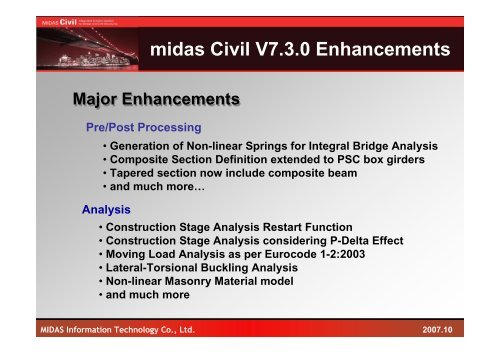
midas <strong>Civil</strong> V7.3.0 <strong>Enhancements</strong>Major <strong>Enhancements</strong>Pre/Post Processing• Generation of Non-linear Springs for Integral Bridge Analysis• Composite Section Definition extended to PSC box girders• Tapered section now include composite beam• and much more…Analysis• Construction Stage Analysis Restart Function• Construction Stage Analysis considering P-Delta Effect• Moving Load Analysis as per Eurocode 1-2:2003• Lateral-Torsional Buckling Analysis• Non-linear Masonry Material model• and much moreMIDAS Information Technology Co., Ltd.<strong>2007</strong>.10
MIDAS <strong>Civil</strong><strong>Civil</strong>Integrated Solution SystemFor Bridge and <strong>Civil</strong> StructurePre Process3. Copy of Tendon ProfileLoad > Prestress Loads > Tendon Profile<strong>2007</strong> UpgradeUpgrade Contents• Copy the tendon profile to another element or a different location within thesame element.Effects & Usage• Easy and convenient way of defining many tendons with a similar profile• This function is useful when each girder has a similar tendon profile as in a PSCGirder bridge or when a similar tendon profile is repeated within a girder as in aPSC Box bridge. The time required for defining tendons is reduced.Copy/Move Tendon Profiledialog boxCopy of of tendon profile in in a PSC Girder bridgeCopy of of tendon profile in in an FCM PSC bridge
MIDAS <strong>Civil</strong><strong>Civil</strong>Integrated Solution SystemFor Bridge and <strong>Civil</strong> Structure<strong>2007</strong> UpgradePre Process4. Input of Reinforcement in a Composite SectionModel > Properties > Reinforcement of Sections• Input the reinforcement data of composite section• Define the Cracked SectionUpgrade ContentsEffects & Usage• The effect of reinforcement on stiffness calculation is considered.• When Cracked Section is defined, the concrete section in negativemoment region is ignored and only the reinforcement is consideredfor analysis.• Can be used in the analysis for a Composite Plate Girder Bridge
MIDAS <strong>Civil</strong><strong>Civil</strong>Integrated Solution SystemFor Bridge and <strong>Civil</strong> StructurePre Process5. Multiple elastic moduli for Composite SectionsModel > Properties > Sections<strong>2007</strong> UpgradeUpgrade Contents• Input multiple elastic moduli, which will be applied to different cases, forthe calculation of composite section properties.• Without performing construction stage analysis, the variation of theelastic modulus can be considered for creep and shrinkage analyses.• Varying stiffness property of post-composite section can be applied todifferent load cases using ‘Boundary Change Assignment to LoadCases/Analyses’.Effects & UsageSection properties of of post-composite section calculated using ‘Long Term’and ‘Shrinkage’ elastic modular ratios
MIDAS <strong>Civil</strong><strong>Civil</strong>Integrated Solution SystemFor Bridge and <strong>Civil</strong> Structure<strong>2007</strong> UpgradePre Process6. Auto generation of Nonlinear Springs for Integral Bridge AnalysisModel > Boundaries > Integral Bridge Spring SupportUpgrade Contents• Generate nonlinear springs to represent the stiffness of the backfill and soilEffects & Usage• Models the abutment-soil interaction as compression-only springs and thesoil adjacent to piles as nonlinear springs. Nonlinear characteristics of springsover the pile height is automatically varied.• Linear, compression-only and Multi-Linear springs are automaticallyassigned to nodes depending upon the spring direction.• By selecting the abutment and pile elements and entering geometry data(ground level, abutment height, deck length, etc.) and soil properties, thespring stiffness at each node is automatically calculated.Define compression-onlysprings for abutment backfillDefine nonlinear springs for thesoils adjacent to to pilesIntegral Bridge Model
MIDAS <strong>Civil</strong><strong>Civil</strong>Integrated Solution SystemFor Bridge and <strong>Civil</strong> StructurePre Process7. Tapered Composite Beam SectionModel > Properties > Section (Tapered Section)<strong>2007</strong> UpgradeUpgrade Contents• Addition of tapered sections for composite beamsEffects & Usage• allows modeling of composite girder by simply specifying dimensions ofdesired tapered section.Examples of of Tapered Composite Girder
MIDAS <strong>Civil</strong><strong>Civil</strong>Integrated Solution SystemFor Bridge and <strong>Civil</strong> Structure<strong>2007</strong> UpgradePre Process8. Composite Section Definition with PSC-Value TypeModel > Properties > Section (Composite )Upgrade Contents• Addition of Composite-PSC Section by using pre-defined PSC-Value Type.Effects & Usage• The bottom section of the composite girder can now be defined byan arbitrary section in addition to currently implemented T and ISections.Example of of Composite-PSC Type Girder
MIDAS <strong>Civil</strong><strong>Civil</strong>Integrated Solution SystemFor Bridge and <strong>Civil</strong> Structure<strong>2007</strong> UpgradePre Process9. European PSC Section DBModel > Properties > Section (PSC -Value )Upgrade Contents• Addition of the most frequently-used PSC Sections from the UK andItaly.Effects & Usage• The section DB can be effectively used in modeling of concrete PSCcomposite girder coupled with Composite-PSC Section TypePSC Sections for UK and Italy
MIDAS <strong>Civil</strong><strong>Civil</strong>Integrated Solution SystemFor Bridge and <strong>Civil</strong> Structure<strong>2007</strong> UpgradePre Process10. Enhancement in Section Stiffness Scale FactorModel > Property > Section Stiffness Scale FactorUpgrade Contents• While defining section stiffness scale factor (SSSF), sectioncoefficients can be defined separately for i-end and j-end.• Different coefficients for composite section can be assigned forbefore and after composite action.Effects & Usage• When analyzing and designing a composite girder section, thesoftware can apply a scale factor to the section stiffness whichexcludes the part of the concrete section with a negative bendingmoment. If different scale factors are used for i-end and j-end, thisfunction can be utilized more effectively.
MIDAS <strong>Civil</strong><strong>Civil</strong>Integrated Solution SystemFor Bridge and <strong>Civil</strong> Structure<strong>2007</strong> UpgradePre Process11. Member Force and Stress Diagram per Part of the Composite SectionResult > Force > Beam DiagramResult > Stress > Beam Stress DiagramUpgrade Contents•Output of the member force and stress diagram of individual parts ofthe composite sectionEffects & Usage• The user can check the member force and stress result much moreeasily by examining a diagram rather than going through tablularoutput.Result table for Composite Section (Previous Version)Diagram of of Part of of the Composite Section for each Construction Stage
MIDAS <strong>Civil</strong><strong>Civil</strong>Integrated Solution SystemFor Bridge and <strong>Civil</strong> Structure<strong>2007</strong> UpgradePre Process12. Initial Forces Table for Last Construction Stage Member ForcesAnalysis > Construction Stage Analysis ControlLoad > Initial Forces > Small Displacement > Initial Element Force (CS)Upgrade Contents• Tabular output of member (beams and trusses) forces at thelast construction stage which can be used as Initial Force inPost CS.Construction Stage Analysis Control DialogEffects & Usage• The user can check converted initial forces that are used forPost CS Analysis.Initial Force(CS) Table for Last Stage Member Force
MIDAS <strong>Civil</strong><strong>Civil</strong>Integrated Solution SystemFor Bridge and <strong>Civil</strong> Structure<strong>2007</strong> UpgradePre Process13. Different Effective Width Scale Factors for i and j-endModel > Boundaries > Effective Width Scale FactorUpgrade Contents•Different scale factors of effective width for i-end and j-end can be specified.• More precise and detailed analysis models can be created by specifying the correctvalues for each end of the girder.Effects & UsageEffective Width Scale Factor - Table
MIDAS <strong>Civil</strong><strong>Civil</strong>Integrated Solution SystemFor Bridge and <strong>Civil</strong> Structure<strong>2007</strong> UpgradePre Process13. Web-based Online ManualHelp > Contents…Upgrade Contents• Online Help is available on World WideWeb.Effects & Usage• Users no longer need to download largehelp file from the website.• Up-to-date contents are always availableto the user.
MIDAS <strong>Civil</strong><strong>Civil</strong>Integrated Solution SystemFor Bridge and <strong>Civil</strong> Structure<strong>2007</strong> UpgradeAnalysis1. Restart function for Construction Stage Analysis2. Construction Stage Analysis with P-Delta Effect taken into account3. Nonlinear Point Springs4. Improvement in Transverse Moving Load Analysis5. Moving Load Analysis as per Eurocode 1-2:20036. Lateral-Torsional Buckling Analysis7. Equivalent stiffness of Cable Element for Construction Stage8. Linear Construction Stage Analysis with Initial Force9. Accumulative Results to Initial Forces for PostCS in Geometric Non-linearCS Analysis10. Limit Strength for Tension only/Compression only Truss11. Masonry Nonlinear Material Model12. Improved Notational Size definition for Composite Girder Sections
MIDAS <strong>Civil</strong><strong>Civil</strong>Integrated Solution SystemFor Bridges and <strong>Civil</strong> Structures<strong>2007</strong> UpgradeAnalysis1. Restart function for Construction Stage AnalysisAnalysis > Construction Stage Analysis ControlComparison of Analysis Time3-Span Continuous FCM BridgeThe total number of stages is 20.Data changed at Stage 10 andanalysis is restarted from Stage 10Analysis TimeBeforeNow203.8 sec 96.5 secAnalyzedfrom thefirst stageAnalyzedfrom the10 th stageSelect the stages for RestartAnalysis > Restart Construction Stage AnalysisRestart the construction stage analysis from the selected stage
MIDAS <strong>Civil</strong><strong>Civil</strong>Integrated Solution SystemFor Bridges and <strong>Civil</strong> Structures<strong>2007</strong> UpgradeAnalysis2. Construction Stage Analysis with P-Delta Effect taken into accountAnalysis > Construction Stage Analysis ControlUpgrade Contents• Perform construction stage analysis and P-Delta analysissimultaneously.• Consider the 2 nd order effect due to the axial force occurring in thegirder and tower of a cable stayed bridge.• P-Delta analysis for a long span Nielsen arch bridge.Effects & UsageBending moment of of a girder with P-Delta effect consideredOption to to include P-Delta effect in in construction stage analysisP-Delta effect ignoredP-Delta effect consideredConstruction stage analysis for a cable stayed bridge with P-Delta effect takeninto accountMax 9737 tonf-mMax 11520 tonf-mIncrease of approximately18%
MIDAS <strong>Civil</strong><strong>Civil</strong>Integrated Solution SystemFor Bridges and <strong>Civil</strong> Structures<strong>2007</strong> UpgradeAnalysis3. Nonlinear Point SpringsModel > Boundary > Point Spring SupportUpgrade Contents• Compression-only/Tension-only and Multi-Linear Type point springshave been added.• Linear, Multi-Linear and Compression-only springs can be used formodeling the soil structure interaction e.g. integral bridge.Effects & Usage• By using Multi-Linear (Bi-Linear) springs, the effects of temperature,braking and acceleration in rail structure interaction can be determined.Point Spring SupportMulti-Linear Point Spring SupportCompression-only/Tension-onlyPoint Spring Support
MIDAS <strong>Civil</strong><strong>Civil</strong>Integrated Solution SystemFor Bridges and <strong>Civil</strong> Structures<strong>2007</strong> UpgradeAnalysis4. Improvement in Transverse Moving Load AnalysisLoad > Moving Load Analysis DataAnalysis > Moving Load Analysis ControlUpgrade Contents• Input Scale Factors when defining traffic lanes.• Distribute vehicles considering the median strip.• Influence line analysis option and result filtering option.Effects & Usage• Specify the number of lanes to the left and to the right ofthe median strip.• By using the ‘Influence Generation Method’ and‘Calculation Filters’ options, the analysis time can bereduced.• Reduce or increase the load by applying Scale Factorsto traffic lanes.Apply scale factors to to traffic lanesConsider the median strip when applyingvehicle loadsInfluence line analysis option and result filtering option
MIDAS <strong>Civil</strong><strong>Civil</strong>Integrated Solution SystemFor Bridges and <strong>Civil</strong> Structures<strong>2007</strong> UpgradeAnalysis5. Moving Load Analysis as per Eurocode 1-2:2003Load > Moving Load Analysis DataSelect the Vehicle Load TypeSelect the Load Model depending onthe Vehicle Load Type• Moving load analysis according to Eurocode 1.Upgrade ContentsEffects & UsageInput the parameters required for the selected Load Model• Perform moving load analysis by means of the vehicle loadsand analysis methods specified in Eurocode 1.
MIDAS <strong>Civil</strong><strong>Civil</strong>Integrated Solution SystemFor Bridges and <strong>Civil</strong> Structures<strong>2007</strong> UpgradeAnalysis6. Lateral-Torsional Buckling AnalysisAnalysis > Buckling Analysis ControlUpgrade ContentsA-A’zA• Addition of lateral-torsional buckling consideration in analysis.yEffects & UsageFlexual-torsional Lateral-torsional buckle BucklingxA’Force Force• The buckling mode around the weak axis is considered for a memberwhich has to resist both bending and shear. This results in more accuratecritical load factors.Test ModelBuckling Result ComparisonMode No Lateral Torsion Lateral Torsion Inc.1 56.49929 33.267582 57.61738 57.63443 69.3207 58.631274 70.54121 70.611255 119.1424 71.426056 119.7788 71.795037 145.7739 72.974778 146.4525 100.1359 216.0261 106.548610 228.6329 119.2809
MIDAS <strong>Civil</strong><strong>Civil</strong>Integrated Solution SystemFor Bridges and <strong>Civil</strong> Structures<strong>2007</strong> UpgradeAnalysis2. Equivalent stiffness of Cable Element for Construction StageAnalysis > Construction Stage Analysis ControlUpgrade Contents• For construction stage analysis with cable elements, the equivalentstiffness of cables will be calculated using the member force at the laststage. In Post CS, the cable members will be considered as trusselements with a calculated equivalent stiffness.Effects & Usage• Load cases considered at post construction stage (Post CS or Completed stage) in cable stayed bridge or suspension bridge analysisinclude linear static load cases (ST), moving load cases (MV), settlement load cases (SM) and response spectrum load cases (RS). Inmoving load analysis, cable elements are automatically considered as truss elements. On the other hand, linear static analysis reflectsthe true stiffness of cable elements. As such, it is not correct to linearly combine the analysis results obtained using different stiffnessesfor the same elements. This function applies equal cable element stiffness to all the load cases acting in Post CS.3. Linear Construction Stage Analysis with Initial ForceAnalysis > Construction Stage Analysis Control• For construction stage analysis, user-defined initial force is consideredas construction stage member force. This member does not generategeometric stiffness.• If the analysis is started at a stage in the middle of the total construction,initial forces will be applied based on generated member forces at thatstage.Upgrade ContentsEffects & Usage
MIDAS <strong>Civil</strong><strong>Civil</strong>Integrated Solution SystemFor Bridges and <strong>Civil</strong> Structures<strong>2007</strong> UpgradeAnalysis4. Accumulative Results to Initial Forces for PostCS in Geometric Non-linearCS AnalysisAnalysis > Construction Stage Analysis ControlUpgrade Contents• Accumulative member forces in geometric nonlinear construction stageanalysis can be applied as initial force in Post CS.Effects & Usage• The final member force, obtained from CS analysis, can be assignedas stiffness during live load and eigenvalue analysis in Post CS.
MIDAS <strong>Civil</strong><strong>Civil</strong>Integrated Solution SystemFor Bridges and <strong>Civil</strong> Structures<strong>2007</strong> UpgradeAnalysis5. Limit Strength for Tension only/Compression only TrussModel > Elements > Create ElementsTensileForce LimitPUpgrade Contents• Addition of Limit Strength for Tension only/Compressiononly Trusses.uEffects & Usage•An additional method of representing materialnonlinearity. Both Tension only / Compression only limitsare provided.PuCompressiveForce Limit
MIDAS <strong>Civil</strong><strong>Civil</strong>Integrated Solution SystemFor Bridges and <strong>Civil</strong> Structures<strong>2007</strong> UpgradeAnalysis6. Masonry Non-linear Material AnalysisModel > Properties > Plastic Material• Addition of masonry non-linear material model.Upgrade Contents-Displays yieldingpoints at at each stepEffects & Usage• Masonry non-linear materials can be effectively used for analysisof traditional arch bridge analysis.• Masonry non-linear materials can only be applied to solidelements.Brick MaterialBed Joint MaterialHead Joint MaterialGeometric Definition
MIDAS <strong>Civil</strong><strong>Civil</strong>Integrated Solution SystemFor Bridges and <strong>Civil</strong> Structures<strong>2007</strong> UpgradeAnalysis7. Notational Size of Composite Girder SectionLoad > Construction State Analysis Data > Composite Section for Construction StageUpgrade Contents• The dialog provides an input box for the notational size ofcomposite girder for construction stage for each part.• Notational size (h) is automatically calculated for sectionsprovided in DB.Effects & Usage• The creep effect for each part can be examined more precisely.