PDF version of this essay that looks nicer - University of Arizona
PDF version of this essay that looks nicer - University of Arizona
PDF version of this essay that looks nicer - University of Arizona

You also want an ePaper? Increase the reach of your titles
YUMPU automatically turns print PDFs into web optimized ePapers that Google loves.
Scaling relations for telescopes, spectrographs,and reimaging instrumentsBenjamin WeinerSteward Observatory<strong>University</strong> <strong>of</strong> <strong>Arizona</strong>bjw @ as.arizona.edu19 September 20081 IntroductionTo make modern astronomical observations, one needs a telescope and a detector, but generallyalso an instrument to modify the light delivered from the telescope. The telescopebrings light from near-infinity to a focus on its focal surface. For large optical/IR telescopes,the focal length at the secondary focus (Cassegrain/Gregorian/Nasmyth) is quite large, andso is the diameter <strong>of</strong> the focal surface. While it is possible to put a detector directly at thesecondary focus, the sizes <strong>of</strong> modern electronic detectors are much smaller than the focal surfaces<strong>of</strong> large telescopes, and so reimaging instrumentation is used to demagnify the image.(The major exceptions are imaging cameras placed at the prime focus <strong>of</strong> the telescope.)In order to do wide field imaging or nearly any kind <strong>of</strong> spectroscopy, we typically place areimaging instrument behind the focal surface, and slits at the focal surface, if needed forspectroscopy. The instrument usually consists <strong>of</strong> a collimating lens, a dispersing element inthe collimated beam if desired, and a camera <strong>that</strong> reimages the collimated beams onto adetector.This document attempts to explain some basics <strong>of</strong> these reimaging systems and to derivesome scaling laws. This is not an optics text. There are many existing texts, but fewspecifically treat astronomical applications and many optics texts drop the reader directlyinto complexities such as the mathematics <strong>of</strong> aberrations. For further background and moredetail, see for example Astronomical Optics by Daniel Schroeder; classic articles on issues<strong>of</strong> spectrograph design include those by I.S. Bowen (1964, volume I <strong>of</strong> Stars and StellarSystems) and R.G. Bingham (1979, QJRAS, 20, 395).The reason for writing <strong>this</strong> is, in part, <strong>that</strong> observers have become more disconnected fromthe instrumentation as it becomes more complex. On my first observing run, I used aninstrument <strong>that</strong> my advisor built, which the two <strong>of</strong> us could pick up, and take <strong>of</strong>f the sidepanels to look at the optical path and adjust the internal focus. Today, there are still somehands-on opportunities, but nobody is going to let a green grad student put his or her handsinside a 8-meter class instrument. So the chance to see how things work is increasinglyrestricted to instrument builders and optical designers. For them, <strong>this</strong> is basic lore <strong>that</strong>“everybody knows,” but it rarely gets taught in a basic optics class.1
2 Reimaging systems2.1 Telescopes and plate scaleSome definitions:f = focal length, mmN = f/number: ratio <strong>of</strong> focal length to aperture or beam diameterD = physical diameters, mms = scale at a focal plane, arcsec/mmθ field = angular field <strong>of</strong> viewTo simplify the optical analysis, I will consider optical elements <strong>that</strong> are focused at infinity.We will deal with mirrors and lenses <strong>that</strong> take incident collimated beams - parallel raybundles, such as from a star at nearly-infinite distance - and turn them into images at afinite distance, or vice versa, turning images into collimated beams. In the case <strong>of</strong> collimatedbeams, a mirror or lens turns the <strong>of</strong>f-axis angle θ <strong>of</strong> an incident beam into an <strong>of</strong>f-axisdisplacement r <strong>of</strong> the image in the focal plane, and the amount <strong>of</strong> the displacement isgoverned by the lens focal length f: r <strong>of</strong>faxis = θ <strong>of</strong>faxis f, where θ is in radians.Cassegrain Gregorian NasmythFigure 1: Telescope designs with locations <strong>of</strong> the secondary focus. The differencebetween Cassegrain and Gregorian is in the location and curvature <strong>of</strong> thesecondary mirror, and in the field curvature <strong>of</strong> the focal plane. The Nasmythfocus is a variant <strong>of</strong> either, using a flat tertiary to change the physical location<strong>of</strong> the focus. Nasmyth foci are useful in alt-azimuth mounted telescopes.Large telescopes are usually derived from a Cassegrain or Gregorian design; newer designs arealmost all alt-azimuth mounting and frequently use a flat tertiary to provide a Nasmyth focus.Cassegrain telescopes have a convex secondary mirror, while Gregorians have a concavesecondary which is located past the primary focus. Cassegrain designs are more commonbecause the overall structure is shorter and the enclosure can be smaller. However, theGregorian has a focal plane which is concave away from the telescope, toward the instrument,while Cassegrains are the opposite. This sense <strong>of</strong> curvature can make it easier to design widefield imagers for a Gregorian. 1The primary mirror in modern large telescopes is quite fast, with f-number ∼ 1 − 3, but thesecondary mirror slows the system down, with f/5 to f/15 being a common range. In Figure1, note <strong>that</strong> the angle <strong>of</strong> convergence at the secondary focus is narrower than it is at the1 The prime examples among 8-meter-class telescopes are the Magellan telescopes, which have an f/11Gregorian secondary.2
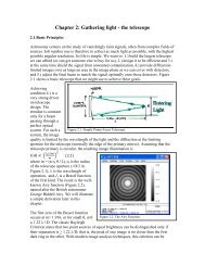
prime focus. If one regards the beam as a cone <strong>of</strong> light, the f-number is simply the ratio <strong>of</strong>height <strong>of</strong> the cone to the base.The plate scale at the secondary focal plane <strong>of</strong> a telescope and the physical diameter <strong>of</strong> thefield <strong>of</strong> view depend on the focal length <strong>of</strong> the telescope f tel (the factor 206265” convertsfrom radians to arcseconds):s tel = 206265”/f tel ,f tel = D tel N tel ,D field = θ field /s tel .The scale at the secondary focal plane is usually large enough <strong>that</strong> it is not a good matchfor modern detectors. For example, at the f/11 focus <strong>of</strong> the 6.5-m Magellan, the plate scaleis 2.9”/mm. A CCD detector with 15 µm pixels would have 0.043”/pixel, which grosslyoversamples a reasonable atmospheric seeing (∼ 0.6 ′′ ).2.2 Simple reimaging systemsFigure 2 illustrates the optical path through a simplified reimaging system, using collimatorand camera lenses to reimage the focal plane onto a detector. The collimator and cameraare drawn as simple lenses; in a real system, they would have to be more complex to avoidaberrations and curvature <strong>of</strong> field. However, the physical sizes <strong>of</strong> collimated beams, thecalculations <strong>of</strong> pixel scales and so on are mostly just dependent on focal lengths and f-numbers, and are similar for simple and complex systems.focal planecollimatorcamera detectorD pupilf collf collpupilf camFigure 2: A typical reimaging system mounted behind the focal surface <strong>of</strong> atelescope, with light entering the focal plane from the left. A beam from asingle on-axis object is shown, diverging from the focal plane, recollimated,and reimaged by the camera onto the detector. The collimator and camerahave been abstracted as simple lenses and the telescope focal plane is drawn asflat, although in a real system it is not. In some instruments the collimator and(less frequently) the camera use mirrors rather than lenses, but the principlesand scaling with focal lengths are similar.Diverging beams emerge from each point on the focal surface and are re-collimated; thediameter <strong>of</strong> a collimated beam is the pupil diameter,3
D pupil = f coll /N tel .The pupil is the aperture <strong>of</strong> the system, here the primary mirror. The collimator forms animage <strong>of</strong> the mirror at the pupil location shown by the vertical dashed line. If we were toput a sheet <strong>of</strong> paper into the beam at <strong>this</strong> location, we would see a donut <strong>of</strong> light, the shape<strong>of</strong> the primary mirror.2.3 Imager field <strong>of</strong> viewfocal planecollimatorcamera detectorpupilFigure 3: The reimaging system with the paths <strong>of</strong> light from on-axis (blacklines) and <strong>of</strong>f-axis objects (red and blue lines). The beams from the <strong>of</strong>f-axisobjects are drawn as parallel to the on-axis beam. These are called “telecentric”beams; real systems are not always telecentric, but the deviations from it aresmall for the purposes <strong>of</strong> <strong>this</strong> discussion. Note <strong>that</strong> the collimator has to belarger than a single beam to accept <strong>of</strong>f-axis beams, and <strong>that</strong> all <strong>of</strong> the beamspass through a “waist” at the pupil.In order to image a nonzero field <strong>of</strong> view, the collimator has to accept <strong>of</strong>f-axis beams, and bephysically wider than D pupil . Figure 3 shows the path <strong>of</strong> <strong>of</strong>f-axis beams through the opticalsystem. For the simplified case in which the <strong>of</strong>f-axis beams are parallel to the optical axis(“telecentric”) and we have abstracted the collimator as a simple lens, thenD coll = D pupil + D field .[Side note: For a complex lens, the D coll isn’t necessarily the diameter <strong>of</strong> all <strong>of</strong> the collimatorglass, but the diameter <strong>of</strong> the collimator entrance pupil. The entrance pupil <strong>of</strong> a lens byitself is not the same thing as the pupil <strong>of</strong> the whole system, indicated by the vertical dottedline. In both cases, pupil means the image <strong>of</strong> an aperture stop, but for the whole system,the aperture stop is the primary mirror.]Note <strong>that</strong> the collimator must have total f-numberN coll = f coll /D coll ,N coll = N telD pupilD coll,4
D pupilN coll = N tel .D pupil + D fieldThe whole collimator lens is faster than the beam delivered by the telescope, because it hasto be wide enough to accept the <strong>of</strong>f-axis beams. Faster lenses or mirrors <strong>that</strong> accept lightfrom larger <strong>of</strong>f-axis angles are harder to construct. Imaging over a wide field also has tocontend with the curvature <strong>of</strong> the telescope focal plane. In practice, both the size <strong>of</strong> theavailable detector and the requirement <strong>of</strong> good image quality for <strong>of</strong>f-axis points set limits onthe field <strong>of</strong> view <strong>of</strong> an instrument.2.4 The pupilThe pupil <strong>of</strong> the spectrograph is an image <strong>of</strong> the primary mirror formed by the secondaryand the collimator. The pupil diameter D pupil is simply set by the expansion <strong>of</strong> the beam asit reaches the collimator, as shown in Figure 2, and its location is set by the focal length <strong>of</strong>the collimator.D pupil = f coll /N tel = D telf collf telD pupil gives the minimum size <strong>of</strong> a dispersing element in the collimated beam. This is acritical number since it sets the minimum size <strong>of</strong> a grating, grism, or other optical device<strong>that</strong> the instrument requires.Off-axis beams, which are displaced by D field /2 in the focal plane, pass through the pupilat an angleθ <strong>of</strong>faxis = D field2f coll.All the light from on- and <strong>of</strong>f-axis beams passes through a “waist” at the pupil. If weintroduced a screen into the light path at the pupil, we would see an in-focus donut-shapedimage <strong>of</strong> the primary mirror. If the screen were placed ahead <strong>of</strong> or behind the pupil, theimage <strong>of</strong> the primary would be not clearly focused.The pupil size interacts with the field <strong>of</strong> view indirectly. Once the collimator focal lengthf coll is chosen, increasing the field <strong>of</strong> view does not increase the pupil size, since all the<strong>of</strong>f-axis beams pass through the “waist” <strong>of</strong> the pupil. However, if we choose a long f coll , then<strong>of</strong>f-axis light enters the collimator at a less extreme angle, so the collimator lens is slowerand easier to design. But long f coll requires a larger pupil. Equivalently, from the equationsfrom N coll above, we see <strong>that</strong> increasing D pupil relative to D field makes the collimator slower.So although field <strong>of</strong> view does not depend directly on pupil size, in real optical designs it isdifficult to image a large field through a small pupil.5
2.5 Reimaging and the scale at the detectorThe camera reimages the collimated beams onto the detector/CCD. The camera has toaccept the collimated beam so it hasD cam = D pupil .In practice, D cam should be slightly greater to avoid vignetting <strong>of</strong>f-axis beams. (This diameteris really the size <strong>of</strong> the camera’s entrance pupil, not the physical size <strong>of</strong> a lens.) Thus thef-number <strong>of</strong> the camera isN cam = f cam /D pupil = N telf camf coll.Because the camera focal length is usually fairly short to get demagnification <strong>of</strong> the focalplane onto a small detector, the camera typically has to be fast (small N cam ). As drawn inFigure 3, the beam converges with a wider (faster) angle at the detector, compared to thebeam delivered by the telescope.An <strong>of</strong>f-axis beam is reimaged at distance from the detector center <strong>of</strong>So <strong>this</strong> means <strong>that</strong>D ccd /2 = θ <strong>of</strong>faxis f cam .D ccd = D fieldf camf coll,s ccd = s telf collf cam,s ccd = 206265”f telf collf cam.The focal plane and plate scale have been demagnified by the ratio <strong>of</strong> collimator to camerafocal lengths. If the collimator is 3x longer than the camera, the detector can be 3x smallerthan the field size in the telescope focal plane. Large telescopes have big focal planes, whiledetectors are usually smaller, so reimaging systems with demagnification allow us to get areasonable field <strong>of</strong> view, and can make the pixel scale a better match to the typical seeing.3 SpectroscopyNow consider putting a grating or grism in the collimated beam to do spectroscopy. Theimportant choice for spectroscopy is the lines/mm <strong>of</strong> the grating, call <strong>this</strong> M grating , whichgoverns the spectral resolution. Typical numbers for large astronomical gratings range from100-1200 lines/mm (apart from echelle gratings, which are used at a different rangle <strong>of</strong>incident angles and in more complex spectrographs).6
3.1 Angles <strong>of</strong> diffraction: the grating equationfromcollimatorgratingnormalαβreflectiongratingtocameraFigure 4: A collimated beam incident from the left on a reflection gratingand the outgoing diffracted beams (red and blue). The incident and diffractedangles α and β are governed by the grating equation and depend on wavelengthand the lines/mm <strong>of</strong> the grating.A transmission grating deviates light <strong>of</strong> wavelength λ by an angle α,sin α = k order λ/l grating ,where l grating = interline spacing, and k order is an integer ≥ 1. Equivalently,sin α = k order λM grating .Let’s work in first order where k order = 1. For a reflection grating the grating equation issin α + sin β = k order λM gratingwhere α and β are the angles <strong>of</strong> incident and diffracted rays with respect to the gratingnormal, shown in Figure 4. The diffracted beams are shown as red and blue. Light from asingle point source produces one incident collimated beam. The diffracted beam <strong>of</strong> a singlepoint source at a single wavelength (e.g. the blue lines) is still collimated and will be imagedat a single point on the detector, while the red lines will be imaged at a different point. Thefact <strong>that</strong> wavelengths are separated in angle, but each single wavelength stays collimated, iswhy we want to have the disperser in the collimated beam.The zeropoint <strong>of</strong> the diffracted angle β depends on the incident angle and grating normal,but the change in β with λ governs the resolution <strong>of</strong> the spectrograph.We’re not directly concerned with the zeropoint <strong>of</strong> β, assuming we have tilted the grating soas to get light into the camera, but with the change in β per wavelength and the resulting7
wavelength scale per pixel. Consider how the camera translates a deviation in angle <strong>of</strong> thediffracted beam to a distance on the detector, r ccd . For a small deviation in angle, dβ, theimage movesdr ccd = f cam dβ.By differentiating the grating equation, for a fixed input angle α,cos β dβ = M grating dλ.For typical spectrograph layouts (other than echelles), β is not large and cos β is slightly< 1.This gives the wavelength/physical scale at the CCD:dλdr ccd=3.2 Spectrograph resolutioncos βf cam M grating.dαcollimatedbeams fromslit edgesαβreflectiongratingtocameradβFigure 5: Collimated beams with a small angular separation dα, as in thebeams from each edge <strong>of</strong> a slit, are incident from the left on a reflection grating.The outgoing diffracted beams (red and blue) have diffracted angle β <strong>that</strong>depends on wavelength. At each wavelength, the outgoing beams are spreadover a small angle dβ due to the finite size <strong>of</strong> the slit.We know the CCD pixel scale in arcsec on the sky, so <strong>this</strong> lets us calculate the resolution<strong>of</strong> the spectrograph for a given slit width in arcsec. Here I will neglect an effect called8
anamorphic demagnification <strong>that</strong> modifies the slit width as projected on the detector 2 . Let’sassume for simplicity <strong>that</strong> our spectrograph is configured such <strong>that</strong> α ≥ β, and dα ≥ dβ.(In practice, one would not design a spectrograph so <strong>that</strong> α = β exactly, because the gratingwould also act as a mirror, reflecting zeroth-order light into the camera.) For some slit widthdW in arcsec, if the anamorphic factor dα/dβ ∼ 1, dW corresponds to a certain number <strong>of</strong>detector pixels as calculated earlier.and we had <strong>that</strong>dr ccd (in mm) = dW/s ccd ,dr ccd =dW206265” f f camtel ,f colldλ = dr ccd cos βf cam M grating.Therefore the delta-wavelength dλ for a slit width dW in arcsec is given bydλ =dW206265”f telf collcos βM grating.Note <strong>that</strong> the camera focal length has dropped out here and <strong>that</strong> f coll is in the denominator,meaning longer collimators give higher resolution for a given slit width. This is because thelonger collimator translates a given slit width into a smaller spread <strong>of</strong> angles, hence a smallerspread <strong>of</strong> wavelength by the grating.3.3 Spectral resolution is controlled by pupil sizeSince f tel = D tel N tel , and f coll = D pupil N tel , we can rewrite the equation for resolution as afunction <strong>of</strong> slit width asdλ =dW206265”D telD pupilcos βM grating.Many factors have dropped out, leaving only telescope and pupil diameters and the lines/mm<strong>of</strong> the grating (and cos β, which is not very adjustable). This equation expresses a fundamentalrelation between telescopes and instruments. Everybody wants a bigger aperturetelescope, large D tel , to gather more light. But in order to get equally high resolution spectra,if we increase D tel , we must also increase D pupil . (M grating is limited, since a 1200lines/mm grating already has interline spacing < 1 micron, close to the wavelengths <strong>of</strong> the2 Anamorphic demagnification comes from the relation <strong>of</strong> incident to diffracted angles. At fixed wavelength,cos α dα + cos β dβ = 0. If the grating tilt is set up such <strong>that</strong> α ≠ β, then dβ ≠ dα. Astronomicalspectrographs are typically configured so <strong>that</strong> β ≥ α and dα/dβ ∼ 1 − 1.5. The diffracted beams from theslit are spread over a smaller angle than the incident beams were, and the slit is demagnified at the detector.This affects the translation <strong>of</strong> slit size into spectral resolution, giving higher resolution by ×1 − 1.5 than wewill calculate for the simple case. See Schweizer (1979, PASP, 91, 149) for a detailed explanation.9
light we are trying to diffract; we can’t make a high-quality large grating <strong>that</strong> is significantlyfiner.)Again, <strong>this</strong> is because increasing the telescope size means we have to scale up the instrument,otherwise a given slit passes a larger range <strong>of</strong> angles to the grating, and <strong>that</strong> lowers theresolution. If we tried to get around <strong>this</strong> by making a faster telescope (smaller N tel ) with asmaller physical scale s tel at the focal plane, the beam emerging from the focal plane andentering the collimator is faster, so it will make a big pupil anyway.Note <strong>that</strong> for given D tel , dλ ∝1D pupil M grating. D pupil M grating is the total number <strong>of</strong> lines inthe grating, or the total number <strong>of</strong> interfering elements; <strong>this</strong> is a common figure <strong>of</strong> merit fordiffracting systems.4 Scaling with telescope sizeThe dλ ∝ D tel /D pupil scaling means <strong>that</strong> large telescopes require instruments with largepupils - and <strong>that</strong> means bigger collimators, cameras, gratings, and detectors. Note <strong>that</strong> <strong>this</strong>is true even for a single-object spectrograph where we don’t need to image a large field <strong>of</strong>view, but want a reasonably high resolution.Constructing large collimators and cameras is a challenge and constructing very large diffractiongratings is extremely difficult. The only way to get around needing a large pupil is tohave a narrower slit. That means either suffering slit losses when the slit gets smaller thanthe seeing, or improving the image resolution delivered to the telescope focal plane, such aswith adaptive optics. This is one reason <strong>that</strong> extremely large telescopes will need and useadaptive optics – to keep some <strong>of</strong> the instruments to a buildable size.Taking an instrument from a small telescope and putting it on a big telescope can be done(if the telescopes have the same f-number - if the f-number is different, it will either underfillor overfill the pupil). However, it is not ideal. The larger telescope has a larger scale at itsfocal plane, so for e.g. a 1.0” slit we need a physically wider slit. With the wider slit, theresolution is worse because we are allowing a larger range <strong>of</strong> angles onto the grating, just asit would be if we sat at the small telescope and opened the slit from 1” to 2”.If we just want to do imaging, we can move a reimaging camera from a small to largetelescope, but <strong>of</strong> course its field <strong>of</strong> view will be proportionately smaller. The product <strong>of</strong>D 2 tel ∗ (field diameter)2 stays constant, so if we need to map an area larger than the field <strong>of</strong>view, the large telescope won’t be faster - unless it has better image quality.A number <strong>of</strong> instruments have used a multi-barrel reimager strategy to cover larger areas.The idea is <strong>that</strong> for a 2x larger diameter telescope, instead <strong>of</strong> scaling up a instrument designby 2x diameter (8x the volume <strong>of</strong> the small instrument, 4x the number <strong>of</strong> detector pixels),one builds 4 <strong>of</strong> the smaller spectrographs and tiles the focal plane with them. This coversthe same field as the one big spectrograph, with the same number <strong>of</strong> pixels, and theoreticallyrequires only 4x the volume <strong>of</strong> the small instrument. Although one has to make 4 <strong>of</strong> eachoptical element, the elements are all smaller, so it should be cheaper and less challenging t<strong>of</strong>abricate. But a drawback is <strong>that</strong> they are each still using a small pupil, so the resolution<strong>of</strong> each spectrograph will be limited: for a given slit and grating, the resolution will be 2x10
worse than it was on the small telescope.AcknowledgmentsMy understanding <strong>of</strong> astronomical instruments and their design considerations has benefittedgreatly from conversations with Ted Williams, Steve Shectman, and Rebecca Bernstein. SylvainVeilleux and Alan Dressler gave me the opportunity to work on an instrument for a largetelescope. During the writing <strong>of</strong> <strong>this</strong> document, I have been supported by NASA/Spitzercontract 1255094 issued by JPL/Caltech.11