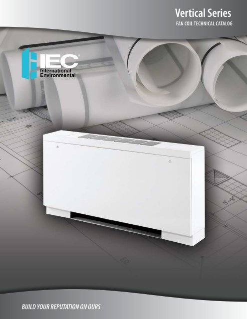
Vertical Series Technical Catalog - IEC International Environmental
Vertical Series Technical Catalog - IEC International Environmental
Vertical Series Technical Catalog - IEC International Environmental
You also want an ePaper? Increase the reach of your titles
YUMPU automatically turns print PDFs into web optimized ePapers that Google loves.
<strong>Vertical</strong> <strong>Series</strong>Motor DataThermal Overload ProtectionAll split-capacitor motors furnished by <strong>IEC</strong> contain internal thermal-overload protection. The overload automatically resetswhen the temperature returns to a safe limit. Electronics Testing Laboratories, Inc. approves the motor and thermal overloadcombination at locked rotor conditions only.Motor Performance Data – FHY, FXY, FSYVoltage115 V60 Hz1-Phase208 V60 Hz1-Phase230 V60 Hz1-Phase277 V60 Hz1-PhaseFan SpeedHighMediumLowHighMediumLowHighMediumLowHighMediumLowUnit Size 02 03 04 06 08 10 12Nominal HP 1/30 1/30 1/12 1/6 1/6 (2) 1/12 (2) 1/6Amps 0.53 0.83 1.40 2.50 2.50 2.80 5.00Watts 85 80 130 200 210 240 370Amps 0.31 0.48 0.70 1.30 1.30 1.30 2.50Watts 50 50 75 140 140 145 265Amps 0.27 0.33 0.47 0.57 0.61 0.40 1.25Watts 35 35 50 60 65 100 125Amps 0.48 0.48 0.69 1.00 1.30 1.38 2.60Watts 85 85 110 190 195 210 340Amps 0.29 0.29 0.40 0.59 0.69 0.80 1.15Watts 60 60 85 130 135 160 220Amps 0.14 0.14 0.22 0.47 0.47 0.45 0.84Watts 28 28 45 90 90 90 170Amps 0.48 0.48 0.69 1.00 1.30 1.38 2.60Watts 100 102 120 205 215 235 370Amps 0.31 0.31 0.43 0.71 0.71 0.85 1.40Watts 70 70 100 150 155 190 285Amps 0.15 0.15 0.24 0.50 0.50 0.50 1.00Watts 0.33 33 55 105 110 115 200Amps 0.35 0.35 0.69 0.91 0.91 1.38 1.82Watts 80 82 140 205 210 270 370Amps 0.26 0.26 0.44 0.57 0.58 0.82 1.10Watts 65 67 110 140 140 200 255Amps 0.16 0.17 0.25 0.34 0.35 0.45 0.65Watts 40 43 65 80 85 125 145NoteS: 1. Total unit motor Amps and Watts are shown.2. Consult factory for 50 Hz applications.10<strong>International</strong> <strong>Environmental</strong> Corporation • <strong>Vertical</strong> <strong>Series</strong> Fan Coil <strong>Technical</strong> <strong>Catalog</strong>www.iec-okc.com
<strong>Vertical</strong> <strong>Series</strong>Motor Data, Cont’d.Motor Performance Data – LHA/LHW, LXA/LXWNote:Voltage115 V60 Hz1-Phase208 V60 Hz1-Phase230 V60 Hz1-Phase277 V60 Hz1-Phase220 V50 Hz1-PhaseFan SpeedHighMediumLowHighLowHighLowHighMediumLowHighMediumLowTotal unit motor Amps and Watts are shown.Motor Performance Data – STY/STWNote:Voltage115 V60 Hz1-PhaseShaded PoleFan SpeedHighMediumLowTotal unit motor Amps and Watts are shown.Unit Size 02 03 04 06Nominal HP 1/20 1/12 1/12 (2) 1/12Amps 0.60 1.60 1.60 3.20Watts 68 135 150 260Amps 0.30 0.60 0.60 1.20Watts 45 65 65 125Amps 0.20 0.30 0.30 0.80Watts 25 40 40 85Amps 0.50 0.66 0.66 1.32Watts 56 109 116 232Amps 0.20 0.30 0.30 0.50Watts 35 55 58 103Amps 0.50 0.66 0.66 1.32Watts 64 128 138 245Amps 0.22 0.28 0.30 0.52Watts 42 65 67 120Amps 0.30 0.50 0.50 1.00Watts 85 135 140 260Amps 0.12 0.33 0.34 0.65Watts 45 85 88 155Amps 0.07 0.22 0.22 0.40Watts 35 55 57 100Amps 0.37 0.39 0.39 0.78Watts 64 128 138 245Amps 0.12 0.33 0.34 0.65Watts 45 85 88 155Amps 0.07 0.22 0.22 0.40Watts 35 55 57 100Unit Size 01 03Nominal HP 1/20 (2) 1/20Amps 1.60 3.20Watts 135 270Amps 1.00 1.91Watts 83 167Amps 0.80 1.54Watts 69 138<strong>International</strong> <strong>Environmental</strong> Corporation • <strong>Vertical</strong> <strong>Series</strong> Fan Coil <strong>Technical</strong> <strong>Catalog</strong>www.iec-okc.com11
<strong>Vertical</strong> <strong>Series</strong>Submittal DataFHY – <strong>Vertical</strong> HideawaySUPPLY AIR OPENINGOPTIONALCONTROLBOXTOP VIEWPLASTICAUXILIARYDRAIN PAN WITH3/4” (19) MPTCONNECTION5(127)4-1/2(114)REMOVABLE FRONTACCESS PANELD4-1/2(114)5-3/4(146)1" (25) SUPPLYDUCTCOLLAR2-1/4(57)5(127)SUPPLYAIR2(51)25(635)9-1/4(235)11-3/4(298)3/4" (19) MOUNTING HOLES(TYP OF 4)5/8" (16) O.D.SUPPLY &RETURNWATERCONNECTIONSAIR VENT1" (25) FILTER4(102)RETURN AIR OPENING5(127)6(152)RETURN 3AIR (76)1-1/2(38)3/4(19)BCMOUNTING HOLESAFRONT VIEWFILTER RETAINERCLIPS1-1/2(38)3/4(19)1-5/8(41)7-5/8(194)9-1/4(235)RIGHT SIDE VIEWUnit ModelDimensions – Inches (Millimeters)Quantity/UnitA B C D Blower MotorUnit Weight*FHY02 25 (635) 22 (559) 23-1/2 (597) 16 (406) 1 1 65FHY03 29 (737) 26 (660) 27-1/2 (698) 20 (508) 1 1 80FHY04 35 (889) 32 (813) 33-1/2 (851) 26 (660) 2 1 90FHY06 45 (1143) 42 (1067) 43-1/2 (1105) 36 (914) 2 1 112FHY08 47 (1194) 44 (1118) 45-1/2 (1156) 38 (965) 2 1 115FHY10 61 (1549) 58 (1473) 59-1/2 (1511) 52 (1321) 4 2 140FHY12 69 (1753) 66 (1676) 67-1/2 (1715) 60 (1524) 4 2 170Notes: * Unit weights (shown in pounds) are based on dry coils, minimum rows and exclude packaging, valves or other components.1. Any modifications to product specifications by any person are subject to acceptance of the <strong>IEC</strong> Home Office. Product specifications aresubject to change without notice.2. All dimensions are +/-1/4"(6).3. RH shown, LH opposite.Drawing is provided for reference only.Dimensions may vary with options ordered.Consult <strong>IEC</strong> website for submittal drawings.12<strong>International</strong> <strong>Environmental</strong> Corporation • <strong>Vertical</strong> <strong>Series</strong> Fan Coil <strong>Technical</strong> <strong>Catalog</strong>www.iec-okc.com
<strong>Vertical</strong> <strong>Series</strong>Submittal Data, Cont’d.FXY – <strong>Vertical</strong> CabinetSTANDARD STAMPEDSUPPLY GRILLE9(229)CONTROL ACCESSDOOR TYP. (2)3-1/4(83)5(127)EDE5(127)3-1/4(83)TOP VIEWSWITCH BOXREMOVABLE FRONTACCESS PANEL1/4 TURN PANELFASTENER TYP.1-1/2(38)5-1/2(140)SUPPLYAIR2(51)9-1/4(235)AIR VENT25(635)11-3/4(298)4(102)3/4" (19)MTG.HOLES(TYP. OF 4)8-3/4(222)9-1/2(241)RETURN AIR OPENINGCMOUNTING HOLESBAFRONT VIEW5(127)8-3/4(222)9-1/2(241)FILTER RETAINERCLIPS5/8" (16) O.D.SUPPLY &RETURNWATERCONNECTIONSPLASTICAUXILIARYDRAINPAN WITH3/4" (19)MPTCONNECTIONRETURNAIR1" (25)FILTER3(76)1-1/2(38)7-1/2(191)9(229)RIGHT SIDE VIEWUnit ModelDimensions – Inches (Millimeters) Quantity/Unit UnitA B C D E Blower Motor Weight*FXY02 41 (1041) 22 (559) 23-1/2 (597) 17-1/4 (438) 3-5/8 (92) 1 1 89FXY03 45 (1143) 26 (660) 27-1/2 (698) 21-1/2 (546) 3-1/2 (89) 1 1 95FXY04 51 (1295) 32 (813) 33-1/2 (851) 26 (660) 4-1/4 (108) 2 1 116FXY06 61 (1549) 42 (1067) 43-1/2 (1105) 39 (991) 2-3/4 (70) 2 1 134FXY08 63 (1600) 44 (1118) 45-1/2 (1156) 39 (991) 3-3/4 (95) 2 1 137FXY10 77 (1956) 58 (1473) 59-1/2 (1511) 52 (1321) 4-1/4 (108) 4 2 169FXY12 85 (2159) 66 (1676) 67-1/2 (1715) 61 (1549) 3-3/4 (95) 4 2 192Notes: * Unit weights (shown in pounds) are based on dry coils, minimum rows and exclude packaging, valves or other components.1. Any modifications to product specifications by any person are subject to acceptance of the <strong>IEC</strong> Home Office. Product specifications aresubject to change without notice.2. All dimensions are +/-1/4"(6).3. RH shown, LH opposite.Drawing is provided for reference only.Dimensions may vary with options ordered.Consult <strong>IEC</strong> website for submittal drawings.<strong>International</strong> <strong>Environmental</strong> Corporation • <strong>Vertical</strong> <strong>Series</strong> Fan Coil <strong>Technical</strong> <strong>Catalog</strong>www.iec-okc.com13
<strong>Vertical</strong> <strong>Series</strong>Submittal Data, Cont’d.FSY – <strong>Vertical</strong> Sloped Top CabinetSTANDARD STAMPEDSUPPLY GRILLE9(229)CONTROL ACCESSDOOR TYP. (2)3-1/4(83)5(127)E D E5(127)3-1/4(83)ATOP VIEWCONTROL BOXREMOVABLE FRONTACCESS PANEL1/4 TURNPANELFASTENERTYP.1-1/4(32)5-3/4(146)SUPPLYAIR2(51)13(331)AIR VENT11-3/4(298)5/8" (16) O.D.SUPPLY &RETURNWATERCONNECTIONS1" (25) FILTER4(102)3/4" (19)MTG. HOLES(TYP. OF 4)8-3/4(222)9-1/2(241)RETURN AIR OPENINGCMOUNTING HOLESBFRONT VIEW5(127)8-3/4(222)9-1/2(241)FILTER RETAINERCLIPSPLASTICAUXILIARYDRAIN PANWITH3/4" (19) MPTCONNECTIONRETURN 3AIR (76)1-1/2(38)7-1/2(191)9(229)RIGHT SIDE VIEWUnit ModelDimensions – Inches (Millimeters) Quantity/Unit UnitA B C D E Blower Motor Weight*FSY02 41 (1041) 22 (559) 23-1/2 (597) 17-1/4 (438) 3-5/8 (92) 1 1 92FSY03 45 (1143) 26 (660) 27-1/2 (698) 21-1/2 (546) 3-1/2 (89) 1 1 98FSY04 51 (1295) 32 (813) 33-1/2 (851) 26 (660) 4-1/4 (108) 2 1 122FSY06 61 (1549) 42 (1067) 43-1/2 (1105) 39 (991) 2-3/4 (70) 2 1 141FSY08 63 (1600) 44 (1118) 45-1/2 (1156) 39 (991) 3-3/4 (95) 2 1 144FSY10 77 (1956) 58 (1473) 59-1/2 (1511) 52-1/8 (1324) 4-1/4 (108) 4 2 178FSY12 85 (2159) 66 (1676) 67-1/2 (1715) 61 (1549) 3-3/4 (95) 4 2 205Notes: * Unit weights (shown in pounds) are based on dry coils, minimum rows and exclude packaging, valves or other components.1. Any modifications to product specifications by any person are subject to acceptance of the <strong>IEC</strong> Home Office. Product specifications aresubject to change without notice.2. All dimensions are +/-1/4"(6).3. RH shown, LH oppositeDrawing is provided for reference only.Dimensions may vary with options ordered.Consult <strong>IEC</strong> website for submittal drawings.14<strong>International</strong> <strong>Environmental</strong> Corporation • <strong>Vertical</strong> <strong>Series</strong> Fan Coil <strong>Technical</strong> <strong>Catalog</strong>www.iec-okc.com
<strong>Vertical</strong> <strong>Series</strong>Submittal Data, Cont’d.LHA/LHW – <strong>Vertical</strong> Lowboy HideawayCONTROL BOX1/4(6)3/8(10)2-1/2(64)3-5/8(92)6(152)2-3/4(70)SUPPLY AIR OPENINGBATOP VIEW1/2(13)6-7/8(175)3/8(10)PLASTICAUXILIARY DRAIN PANWITH 3/4" (19) MPT CONNECTION1" (25) FILTER6(152)1/2(13)3(76)ACBFRONT VIEW3(76)6-1/4(159)1 (25) SUPPLYDUCT COLLAR3-1/2(89)5/8' (16) O.D.SUPPLY & RETURNWATER CONNECTIONS14-3/8" (368)FOR SHORTMODEL (LHA)16-3/8" (419)FOR TALLMODEL (LHW)PLASTICAUXILIARYDRAIN PAN3/4" (19) MPTCONNECTIONAIRVENT1-1/4(32)RETURNAIR3(76)1-1/4(32)5(127)SUPPLYAIR10(254)11-1/4(286)5(127)RIGHT SIDE VIEWUnit ModelDimensions – Inches (Millimeters)Quantity/UnitA B C Blower MotorUnit Weight*LHA/LHW02 23 (584) 22 (559) 17 (432) 2 1 50LHA/LHW03 28 (711) 27 (686) 22 (559) 2 1 60LHA/LHW04 36 (914) 35 (889) 30 (762) 2 1 72LHA/LHW06 50 (1270) 49 (1245) 44 (1118) 4 2 110Notes: * Unit weights (shown in pounds) are based on dry coils, minimum rows and exclude packaging, valves or other components.1. Any modifications to product specifications by any person are subject to acceptance of the <strong>IEC</strong> Home Office. Product specifications aresubject to change without notice.2. All dimensions are +/-1/4"(6).3. RH shown, LH opposite.Drawing is provided for reference only.Dimensions may vary with options ordered.Consult <strong>IEC</strong> website for submittal drawings.<strong>International</strong> <strong>Environmental</strong> Corporation • <strong>Vertical</strong> <strong>Series</strong> Fan Coil <strong>Technical</strong> <strong>Catalog</strong>www.iec-okc.com15
<strong>Vertical</strong> <strong>Series</strong>Submittal data, Cont’d.LHW - <strong>Vertical</strong> Lowboy Hideaway w/Electric Heat2-1/2(64)6(152)2-3/4(70)CONTROL BOXSUPPLY AIR OPENINGTOP VIEW1/4(6)1/2(13)3/8(10)6-7/8(175)3-5/8(92)3/8(10)PLASTICAUXILIARY DRAIN PANWITH 3/4" (19) MPT CONNECTION6-2/5(163)3(76)ACELECTRICAL SHEATHHEATER ELEMENT3(76)1 (25) SUPPLYDUCT COLLAR5/8' (16) O.D.SUPPLY & RETURNWATER CONNECTIONS1-1/4(32)5(127)SUPPLYAIR5(127)AIRVENT16-3/8" (419) FOR TALL MODEL1" (25)FILTER3-1/2(89)PLASTICAUXILIARYDRAIN PAN3/4" (19) MPTCONNECTIONRETURNAIR3(76)1/2(13)B6-1/4(159)1-1/4(32)10(254)11-1/4(286)FRONT VIEWRIGHT SIDE VIEWUnit ModelDimensions – Inches (Millimeters)Quantity/UnitA B C Blower MotorUnit Weight*LHW02 23 (584) 22 (559) 17 (432) 2 1 50LHW03 28 (711) 27 (686) 22 (559) 2 1 60LHW04 36 (914) 35 (889) 30 (762) 2 1 72LHW06 50 (1270) 49 (1245) 44 (1118) 4 2 110Notes: * Unit weights (shown in pounds) are based on dry coils, minimum rows and exclude packaging, valves or other components.1. Any modifications to product specifications by any person are subject to acceptance of the <strong>IEC</strong> Home Office. Product specifications aresubject to change without notice.2. All dimensions are +/-1/4"(6).3. RH shown, LH opposite.Drawing is provided for reference only.Dimensions may vary with options ordered.Consult <strong>IEC</strong> website for submittal drawings.16<strong>International</strong> <strong>Environmental</strong> Corporation • <strong>Vertical</strong> <strong>Series</strong> Fan Coil <strong>Technical</strong> <strong>Catalog</strong>www.iec-okc.com
<strong>Vertical</strong> <strong>Series</strong>Submittal data, Cont’d.LXA/LXW – <strong>Vertical</strong> Lowboy and <strong>Vertical</strong> Lowboy Tall CabinetCONTROL ACCESSDOOR (2)12-1/4(311)3-1/4(83)5(127)CDTOP VIEWC5(127)3-1/4(83)CONTROL BOXREMOVABLEFRONT PANEL5/8" (16) O.D.SUPPLY & RETURNWATER CONNECTIONS1/4 TURN PANELFASTENER TYP.STAMPEDSUPPLYGRILLEAIR VENT1-1/8(29)12-1/4(311)6(152)SUPPLYAIR5-1/8(130)14-1/2" (368)FOR SHORTMODEL (LXA)16-1/2" (419)FOR TALLMODEL (LXW)1" (25)FILTERSTAMPEDRETURNGRILLERETURNAIR3-1/2(89)3(76)9-1/2(241)UNIT SERIAL PLATE,WIRING DIAGRAM &CAUTION LABELBAFRONT VIEW9-1/2(241)RETURNAIR GRILLEPLASTICAUXILIARYDRAINPAN WITH3/4" (19) MPTCONNECTION2(51)10-1/4(260)RIGHT SIDE VIEWUnit ModelDimensions – Inches (Millimeters)Quantity/UnitA B C D Blower MotorUnit Weight**LXA/LXW02 41 (1041) 22 (559) 3-3/4 (95) 17 (432) 2 1 72LXA/LXW03 46 (1168) 27 (686) 4 (102) 21-1/2 (546) 2 1 100LXA/LXW04 54 (1372) 35 (889) 3-5/8 (92) 30-1/4 (768) 2 1 108LXA/LXW06 68 (1727) 49 (1245) 4-1/16 (103) 43-3/8 (1102) 4 2 154Notes: ** Height dimensions different for LHA/LHW. See drawing.** Unit weights (shown in pounds) are based on dry coils, minimum rows and exclude packaging, valves or other components.1. RH shown, LH opposite.2. All dimensions are +/-1/4"(6).3. Dimensions inside ( ) are millimeters.4. Any modifications to product specifications by any person are subject to acceptance of the <strong>IEC</strong> Home Office. Product specifications aresubject to change without notice.Drawing is provided for reference only.Dimensions may vary with options ordered.Consult <strong>IEC</strong> website for submittal drawings.<strong>International</strong> <strong>Environmental</strong> Corporation • <strong>Vertical</strong> <strong>Series</strong> Fan Coil <strong>Technical</strong> <strong>Catalog</strong>www.iec-okc.com17
<strong>Vertical</strong> <strong>Series</strong>submittal data, Cont’d.LXW – <strong>Vertical</strong> Lowboy Tall Cabinet with Electric HeatCONTROL BOX12-1/4(311)3-1/4(83)5(127)CDTOP VIEWC5(127)3-1/4(83)CONTROL BOXELECTRICAL SHEATHHEATER ELEMENTREMOVABLEFRONT PANEL5/8" (16) O.D.SUPPLY & RETURNWATER CONNECTIONS1/4 TURN PANELFASTENER TYP.STAMPEDSUPPLYGRILLE(NOTE 5)AIR VENT1-1/8(29)12-1/4(311)6(152)SUPPLYAIR5-1/8(130)3-1/2(89)16-1/2" (419)FORTALL MODEL1" (25)FILTERSTAMPEDRETURNGRILLERETURNAIR3(76)9-1/2(241)UNIT SERIAL PLATE,WIRING DIAGRAM &CAUTION LABELBAFRONT VIEW9-1/2(241)RETURNAIR GRILLEPLASTICAUXILIARYDRAIN PANWITH 3/4" (19)MPT CONNECTION2(51)10-1/4(260)RIGHT SIDE VIEWUnit ModelDimensions – Inches (Millimeters)Quantity/UnitA B C D Blower MotorUnit Weight**LXA/LXW02 41 (1041) 22 (559) 3-3/4 (95) 17 (432) 2 1 72LXA/LXW03 46 (1168) 27 (686) 4 (102) 21-1/2 (546) 2 1 100LXA/LXW04 54 (1372) 35 (889) 3-5/8 (92) 30-1/4 (768) 2 1 108LXA/LXW06 68 (1727) 49 (1245) 4-1/16 (103) 43-3/8 (1102) 4 2 154Notes: ** Height dimensions different for LHW. See drawing.** Unit weights (shown in pounds) are based on dry coils, minimum rows and exclude packaging, valves or other components.1. RH shown, LH opposite.2. All dimensions are +/-1/4"(6).3. Dimensions inside ( ) are millimeters.4. Any modifications to product specifications by any person are subject to acceptance of the <strong>IEC</strong> Home Office. Product specifications aresubject to change without notice.5. Stamped supply only for units with electric heat.Drawing is provided for reference only.Dimensions may vary with options ordered.Consult <strong>IEC</strong> website for submittal drawings.18<strong>International</strong> <strong>Environmental</strong> Corporation • <strong>Vertical</strong> <strong>Series</strong> Fan Coil <strong>Technical</strong> <strong>Catalog</strong>www.iec-okc.com
<strong>Vertical</strong> <strong>Series</strong>Submittal Data, Cont’d.STY/STW – <strong>Vertical</strong> Recessed Cabinet7/8(22)A7/8C 107/8(22)(22)CB7/8(22)TOP VIEW(EXTENDED MODEL)STWTOP VIEW(STANDARD MODEL)STY1(25)5(127)8(203)DEA23-1/2(597)1(25)5(127)8(203)DBE5/8" (16) O.D.SUPPLY & RETURNWATER CONNECTIONSREMOVABLEFRONT PANEL3/4" (19) I.D. DRAINHOSE CONNECTIONSUPPLYAIRSTAMPEDSUPPLYGRILLESTAMPEDRETURNGRILLEWITH1" (25)FILTERRETURNAIR1(25)3/4(19)AIR VENT23-1/222(597)(559)1(25)JUNCTION BOXFRONT VIEWPLASTICAUXILIARYDRAIN PAN(SHIP LOOSE)10" (254)VALVE COMPARTMENT1(25)FRONT VIEW3(76)4-1/8(105)7-1/8(181)3/4(19)RIGHT SIDE VIEWUnit ModelDimensions – Inches (Millimeters) Quantity/Unit UnitA B C D E Blower Motor Weight*STY/STW01 25-3/4 (654) 15-3/4 (400) 14 (356) 1-1/2 (38) 12-3/4 (324) 1 1 40STY/STW03 39-3/4 (1010) 29-3/4 (756) 28 (711) 1-15/16 (49) 25-7/8 (657) 2 2 74Notes: ** Unit weights (shown in pounds) are based on dry coils, minimum rows and exclude packaging, valves or other components.1. Any modifications to product specifications by any person are subject to acceptance of the <strong>IEC</strong> Home Office. Product specifications aresubject to change without notice.2. All dimensions are +/-1/4"(6).3. RH shown, LH opposite.Drawing is provided for reference only.Dimensions may vary with options ordered.Consult <strong>IEC</strong> website for submittal drawings.<strong>International</strong> <strong>Environmental</strong> Corporation • <strong>Vertical</strong> <strong>Series</strong> Fan Coil <strong>Technical</strong> <strong>Catalog</strong>www.iec-okc.com19
<strong>Vertical</strong> <strong>Series</strong>Standard Features and OptionsFeatures and OptionsStandardFactory InstalledOptionField InstalledOptionFactory SpecialQuoteAir Flow ArrangementFront Return/Top Supply (FHY, FSY, FXY, LHA, LXA)XFront Return/Front Supply (FHY, FXY, FSY)XFront Return/Front Supply (STY, STW)XCoils2-Rows 2-Pipe (LHA, LHW, LXA, LXW, STY, STW)X3-Rows 2-Pipe (FXY, FSY, FHY)X3-Row 2-Pipe (LHA, LHW, LXA, LXW)X4-Rows 2-Pipe (LHA, LHW, LXA, LXW)X2/1-Rows 4-Pipe (LHA, LHW, LXA, LXW)X3/1, 3/2, or 4/1-Rows (FXY, FSY, FHY) XManual Air VentXAutomatic Air VentXDX CoilsXSteam Coils X XConnectionRight or Left (Same End)XDrain PanGalvanized Internally Coated with a 2 part closed cell foamXStainless Steel Externally CoatedXPlastic Auxiliary Drain PanXFin MaterialAluminum w/Galvanized End SheetsXCopper w/Stainless End Sheets & Bottom Coil Baffle X XSheath Type Electric Heater (Total and Auxiliary)XFilters1" Throwaway Non-woven Synthetic X1" Permanent X1" MERV 8 Pleated XInsulation1/2" Standard Fiberglass X1/2" Premium IAQ Fiberglass X1/2" Foil Face X1/4" Closed Cell XMotor TypePSC Motors w/Quick Connect Plug (F*Y, L*Y)XMotor Voltage115/1/60 3-Speed X208/230/277/1/60, 220/1/50 3-Speed XSupply/Return Air GrillesStamped Supply Grille (FXY, FSY, LXA, LXW, STY, STW)XStamped Return Grille (FXY, FSY)XStamped Return Grille (STY, STW)XCustom ColorsXControlsService Switch with Lockout TabsXSingle Point Power ConnectionXIncoming Power FusingX24 V Controls XCondensate Overflow SwitchXThree Speed SwitchXThermostatsUnit MountedXWall MountedXCustom Controls (DDC) X XOutside Air DampersManual Controlled Damper (FHY, FXY, FSY, LHA, LHW, LXA, LXW)XRemote Controlled Damper (FHY, FXY, FSY)XMotorized Controlled Damper (FHY, FXY, FSY)XOutside Air Box (FHY, FXY, FSY)XDecorative Wall Panels (FHY)XTamperproof Locks (Camlock)Access Panels (FXY, FSY, LXA, LXW)XAccess Doors (FXY, FSY, LXA, LXW) X X20<strong>International</strong> <strong>Environmental</strong> Corporation • <strong>Vertical</strong> <strong>Series</strong> Fan Coil <strong>Technical</strong> <strong>Catalog</strong>www.iec-okc.com
<strong>Vertical</strong> <strong>Series</strong>Standard Features and Options, Cont’d.FiltersAll <strong>Vertical</strong> <strong>Series</strong> units non-woven, synthetic throwaway filters furnished as standard equipment. Cleanable or MERV 8pleated filters are optional.Unit SizeNominal One-Inch Filter Size – Inches (Millimeters)FHY, FXY, FSY LHA/LHW, LXA/LXW STY/STW01 – – 10" x 14-1/2" (254 x 368)02 7-3/4" x 21-3/4" (197 x 552) 7" x 21-3/4" (178 x 502) –03 7-3/4" x 25-3/4" (197 x 654) 7" x 26-3/4" (178 x 679) 10" x 28" (254 x 711)04 7-3/4" x 31-3/4" (197 x 806) 7" x 34-3/4" (178 x 883) –06 7-3/4" x 41-3/4" (197 x 1060) 7" x 48-3/4" (178 x 1238) –08 7-3/4" x 43-3/4" (197 x 1111) – –10 7-3/4" x 57-3/4" (197 x 1467) – –12 7-3/4" x 65-3/4" (197 x 1670) – –Note: Sizes shown are nominal ordering sizes.<strong>International</strong> <strong>Environmental</strong> Corporation • <strong>Vertical</strong> <strong>Series</strong> Fan Coil <strong>Technical</strong> <strong>Catalog</strong>www.iec-okc.com21
<strong>Vertical</strong> <strong>Series</strong>Options and AccessoriesControl PackagesControls:As detailed in the table below, we offer a control for mostof the customer needs. Additional controls and devices areavailable to meet even the most demanding operating logic.Three-speed Fan ControlAll of our basic control schemes utilize a 3-speed switch tomodulate the cooling output, to maximize the percentageof latent heat removal, and to further minimize the soundlevel when maximum cooling or heating performance is notrequired.Low Voltage Control (24 V)A low voltage control is available with all of our controlschemes.Condensate Overflow SwitchThis switch shuts down the unit when the water level in thedrain pan reaches an unsafe level. Building code changes inmuch of our country now require this type of device.Service SwitchesWe offer concealed service switches for use by maintenanceand service personnel to shut off the power while workingon the unit.FusingWe offer incoming power fusing for all units as well asblower motor and control sub-fusing for units that useelectric heat. The blower motor and control sub-fusing(single power source wiring) is required when single sourcepower with electric heat is specified.Unit Mounted <strong>Series</strong> 156 Basic Wall <strong>Series</strong> 4039 <strong>Vertical</strong> Wall <strong>Series</strong> 15524 V Programmable andNon-ProgrammableDigital <strong>Series</strong>Unit TypeControlOptionSystem TypeCodeChangeoverTypeUnitMounted<strong>Series</strong>Basic and<strong>Vertical</strong> Wall<strong>Series</strong>24 V Programmableand Non-Programmable <strong>Series</strong>– Manual Fan Manual A None – – –Heat Only G None Cool Only H None 2-PipeJ Manual – –Heat/CoolK Automatic Heat/Cool withL Manual – –Valve CycleAuxiliary Electric Heat M Automatic 4-PipeCool with TotalElectric HeatHeat/CoolN Manual – –P Automatic Q Manual – –R Automatic 22<strong>International</strong> <strong>Environmental</strong> Corporation • <strong>Vertical</strong> <strong>Series</strong> Fan Coil <strong>Technical</strong> <strong>Catalog</strong>www.iec-okc.com
<strong>Vertical</strong> <strong>Series</strong>Options and Accessories, Cont’d.ThermostatsThermostats System Function ModeControl Type*C 4 A B P N2-Pipe Heat Only ACO X X X X X X2-Pipe Cool Only ACO X X X X X XACO X X X X X X2-PipeHeat/CoolMCO N/A X X X X XBasicHeat/Cool with Auxiliary Electric ACO X X X X X XControl 2-PipeHeatMCO N/A X X X X XNeedsACO X X X X X X2-Pipe Heat/Cool with Total Electric HeatMCO N/A X X X X X4-PipeHeat/CoolACO X X X X X XMCO N/A X X X X X24 Volts X X X X X XProgrammable N/A N/A N/A N/A X N/ANon-Programmable X X X X N/A XThermostatRemote Wall Mounted N/A X X X X XFeatures3-Speed Fan X X X X X XContinuous Fan X X X X X XAll listedCycling Fan N/A N/A N/A N/A X XcontrolsincludeRemote Temperature Sensor N/A N/A Opt Opt X XfanAdjustable Operating Range Kit Kit Kit Kit X Xswitching.Touch Pad/Digital Display N/A N/A N/A N/A X XLocal Temperature Set-Back N/A N/A N/A N/A X XWater Temperature Purge Cycle N/A N/A N/A N/A X XPipe Sensor N/A N/A N/A N/A X X*Control Type Legend: C Unit Mounted <strong>Series</strong> 1564 Wall <strong>Series</strong> 4039A Wall <strong>Series</strong> 155 <strong>Vertical</strong>B Wall <strong>Series</strong> 155 HorizontalP 24 V Digital Programmable Wall <strong>Series</strong>N 24 V Digital Non-Programmable Wall <strong>Series</strong>Control Options• 24 V control packages• Unit-mounted fan switches (Special Quote)• Single power source wiring (motor/control fusing)• Incoming power fusing• Service switches• Minimum room temperature thermostats (SpecialQuote)• Low voltage remote shutdown relays (Special Quote)• Fan and valve cycle applications (Special Quote)• Thermostats available with large letter print forhandicap applications (Special Quote)• DX coil applications<strong>International</strong> <strong>Environmental</strong> Corporation • <strong>Vertical</strong> <strong>Series</strong> Fan Coil <strong>Technical</strong> <strong>Catalog</strong>www.iec-okc.com23
<strong>Vertical</strong> <strong>Series</strong>Options and Accessories, Cont’d.Outside Air DampersFHY, FXY, FSY, LHA/LHW and LXA/LXW models may besupplied with an outside air inlet connection. A damper forcontrol of the outside air is provided, and several styles ofoutside air damper control are available.Style AControl of the damper is by manual operation of the damperin the unit return air toe space. FHY, FXY and FSY modelsare provided with a lever arm on the damper. LHA/LHW andLXA/LXW models are provided with a sliding damper (notshown in illustration below).Style BFor FHY, FXY and FSY models only, a remote damperoperator is provided which allows control of the damperfrom under one of the control access doorsStyle CFor FHY, FXY and FSY models only, control of the damperis achieved by a motorized operator installed in the lefthandend compartment. Consult the factory for applicationrestrictions.Outside Air Opening Dimensions – Inches (Millimeters)Unit SizeNominal CFMFHY, FXY, FSYLHA/LHW, LXA/LXWFront View (A) Side View (B) Front View (A) Side View (B)02 200 8" (203) 2" (51) 6" (152) 2" (51)03 300 10" (254) 2" (51) 6" (152) 2" (51)04 400 12" (305) 2" (51) 6" (152) 2" (51)06 600 14" (356) 2" (51) 6" (152)* 2" (51)*08 800 18" (457) 2" (51) – –10 1000 27" (686) 2" (51) – –12 1200 27" (686) 2" (51) – –Note:* Lowboy size 06 is provided with two 6" x 2" (152 x 51) openings.B1/2"ASide ViewFront View24<strong>International</strong> <strong>Environmental</strong> Corporation • <strong>Vertical</strong> <strong>Series</strong> Fan Coil <strong>Technical</strong> <strong>Catalog</strong>www.iec-okc.com
<strong>Vertical</strong> <strong>Series</strong>Options and Accessories, Cont’d.Outside Air Wall BoxesOptional outside air wall boxes are constructed of aluminumto minimize corrosion. A louvered grille caps the wall boxon the exterior side. A fine mesh insect screen is installedbehind the louver on the inside of the box.Standard wall box depth is six inches with the widthand length dimensions established to be used with theappropriate outside air openings.Unit SizeNominal CFMOutside Air Opening Dimensions – Inches (Millimeters)FHY, FXY, FSYFront View (A)Side View (B)02 200 8-1/4" (203) 2-1/8" (54)03 300 10-1/4" (260) 2-1/8" (54)04 400 12-1/4" (311) 2-1/8" (54)06 600 14-1/4" (362) 2-1/8" (54)08 800 18-1/4" (464) 2-1/8" (54)10 1000 27-1/4" (692) 2-1/8" (54)12 1200 27-1/4" (692) 2-1/8" (54)6"2-1/4"2-1/4"2-1/8"AFront ViewSide ViewTypical Wall Installation<strong>International</strong> <strong>Environmental</strong> Corporation • <strong>Vertical</strong> <strong>Series</strong> Fan Coil <strong>Technical</strong> <strong>Catalog</strong>www.iec-okc.com25
<strong>Vertical</strong> <strong>Series</strong>Options and Accessories, Cont’d.Decorative Wall PanelsOptional decorative wall panels are used with FHY modelswhen fully recessed into the wall of the conditioned space.The wall panels cover the recessed unit on all sides and canbe removed for access to the unit for servicing. The wallpanel provides the air seal for the front of the unit; therefore,installation alignment is critical. Consult the factory forinstallation instructions.Two styles of decorative wall panels are available – Style U,with stamped return and supply louvers and front facinghinged-access doors; and Style V, with stamped returnlouvers only.Nominal CFMStyles U and V Panel Width (A)Inches (Millimeters)200 40" (1016)300 44" (1118)400 50" (1270)600 60" (1524)800 62" (1575)1000 76" (1930)1200 84" (2134)A30"Style UA30"Style V26<strong>International</strong> <strong>Environmental</strong> Corporation • <strong>Vertical</strong> <strong>Series</strong> Fan Coil <strong>Technical</strong> <strong>Catalog</strong>www.iec-okc.com
<strong>Vertical</strong> <strong>Series</strong>Options and Accessories, Cont’d.Supply Air GrillesUnit Size Nominal CFMRecommended Grille Sizes – Inches (Millimeters)FXY, FSY LXA/LXW FHY LHA/LHW02 200 16" x 6" (406 x 152) 16" x 6" (406 x 152) 16" x 5" (406 x 127) 16" x 5" (406 x 127)03 300 20" x 6" (508 x 152) 22" x 6" (559 x 152) 20" x 5" (508 x 127) 22" x 5" (559 x 127)04 400 26" x 6" (660 x 152) 30" x 6" (762 x 152) 26" x 5" (660 x 127) 30" x 5" (762 x 127)06 600 36" x 6" (914 x 152) 44" x 6" (1118 x 152) 36" x 5" (914 x 127) 44" x 5" (1118 x 127)08 800 38" x 6" (965 x 152) – 38" x 5" (965 x 127) –10 1000 52" x 6" (1321 x 152) – 52" x 5" (1321 x 127) –12 1200 60" x 6" (1524 x 152) – 60" x 5" (1524 x 127) –Notes: 1. Refer to Submittal Data, pages 12 through 19, for actual unit supply air opening dimensions.2. FXY, FSY and LXA/LXW models supply air grilles are factory installed.3. Consult factory for application restrictions using double-deflection grilles with electric heat and maximum coil rows.4. FHY and LHA/LHW models supply air grilles are shipped loose.Optional Double-deflection, Aluminum-finish Supply Grille(Shown in Top Panel)Optional Double-deflection, Integral Supply Grille (FXY, FSY and LXA/LXW Models Only),Painted to Match Color of Unit (Shown in Top Panel)Optional Return Air Grille(FXY and FSY Models Only),Painted to Match Color of Unit<strong>International</strong> <strong>Environmental</strong> Corporation • <strong>Vertical</strong> <strong>Series</strong> Fan Coil <strong>Technical</strong> <strong>Catalog</strong>www.iec-okc.com27
<strong>Vertical</strong> <strong>Series</strong>Piping Packages (Typical)Two-way Motorized Control ValveIn a two-way motorized control valve package, the motordrives the valve open, and a spring returns the valve to anormally closed position. No water flows with the unit off.The standard supply connection from the coil will accepta swaged copper fitting for field brazing. As an option, thisconnection may be factory furnished with a union. When aswage is necessary, it becomes part of the valve package.The isolation, or ball, valve in the return piping is shippedloose for field installation.Air VentCoil2- way ValveBall Valve(Shipped Loose)RTwo-way Motorized Control Valve WithAquastat Bypass LineIn a two-way motorized control valve package, the motordrives the valve open, and a spring returns the valve toa normally closed position. No water flows through thecoil with the unit off. The aquastat bypass line allows asmall amount of water to flow from the supply to thereturn piping when the control valve is closed. The straponaquastat senses whether the flowing water is beingchilled or heated and switches a contact closed to provideautomatic summer/winter changeover (ACO) for the system.When a 2-pipe cooling/heating system with optionalauxiliary electric heat is desired, an additional aquastat isrequired.Air VentSwageThree-way Motorized Control ValveBall ValveIn a three-way motorized control valve package, a divertingvalve controls water flow to the coil. When the unit is off,water bypasses the coil and flows directly to the systemreturn. A balancing valve may be specified in the bypass lineto permit equal flow balancing.Air VentCoilSwage3- way ValveBall ValveOptionalBalance ValveRSCoilSwageSwage2- way ValveAAquastatBall ValveAquastat BleedBypass LineNotes: 1. Please note that project specifications for system pressure,pressure drop limitations and flow rate should be checkedprior to selecting specific components or the valvepackage size.2. The supply and return piping connections of the factoryprovidedvalve package are either swaged for field brazing(standard) or union fitted (optional) for field connection tothe coil.3. Consult <strong>IEC</strong>’s Valve Packages and Piping Componentsmanual or your local representative for detailed pipingand valve application information. Factory-providedvalve packages are assembled, brazed, wired electricallyand dry-fit to the coil connections before shipping. Fieldbrazing to the coil completes the installation. Someapplications dictate shipping isolation valves loose.RSSwageAAquastatBall ValveS28<strong>International</strong> <strong>Environmental</strong> Corporation • <strong>Vertical</strong> <strong>Series</strong> Fan Coil <strong>Technical</strong> <strong>Catalog</strong>www.iec-okc.com
<strong>Vertical</strong> <strong>Series</strong>Mechanical SpecificationsGENERAL DESCRIPTION–VERTICAL FAN COIL UNITSFHY – <strong>Vertical</strong> HideawayFSY – <strong>Vertical</strong> Sloped Top CabinetFXY – <strong>Vertical</strong> CabinetLHA – <strong>Vertical</strong> Lowboy HideawayLHW – <strong>Vertical</strong> Lowboy Tall HideawayLXA – <strong>Vertical</strong> Lowboy CabinetLXW – <strong>Vertical</strong> Lowboy Tall CabinetSTY – <strong>Vertical</strong> Recessed CabinetSTW – <strong>Vertical</strong> Recessed Wide CabinetPART 11.1 SUMMARYThis section includes fan coil units and accessories.1.2 SYSTEM DESCRIPTION<strong>Vertical</strong> Fan Coil Units, 2-pipe, 4-pipe, or 2-pipe withelectric heat, hideaway or cabinets that are floormounted.1.3 QUALITY ASSURANCECoils shall be tested in accordance with AHRIStandard 440. Each coil shall be factory tested forleakage at 300 psig air pressure with coil submergedin water. Insulation and adhesive shall meet NFPA-90Arequirements for flame spread and smoke generation.B. FHY, LHA, LHW Floor Hideaway Units:1. Cabinet shall be made of heavy gaugegalvanized steel.2. Interior surfaces shall be lined with ½" thickstandard fiberglass (½" premium IAQfiberglass, ½" foil face, or ¼" closed cell)insulation.3. Units shall be supplied with a 1" collar for ductconnection.4. Units shall have a combination condensatedrain pan and fan deck constructed of16-gauge galvanized (stainless) steel andextending the entire length of the unit.5. Galvanized drain pans shall be coated with a2-part closed cell foam insulation.6. Units shall have 1" throwaway non-wovensynthetic (permanent or MERV 8 pleated)filters.Base or “standard” units shall be ETL listed.1.4 DELIVERY, STORAGE AND HANDLINGUnit shall be handled and stored in accordance with themanufacturer’s instructions.PART 2–PRODUCTS2.1 MANUFACTURERBasis of design shall be fan coils by <strong>International</strong>Environment Corporation.2.2 CONFIGURATIONA. General:Factory assembled <strong>Vertical</strong> fan coil units completewith water coil, fan, motor, drain pan, and allrequired wiring, piping and controls.C. FXY, FSY, LXA, LHW Floor Exposed Units:1. Units shall be constructed of heavy gaugegalvanized steel.<strong>International</strong> <strong>Environmental</strong> Corporation • <strong>Vertical</strong> <strong>Series</strong> Fan Coil <strong>Technical</strong> <strong>Catalog</strong>www.iec-okc.com29
<strong>Vertical</strong> <strong>Series</strong>Mechanical Specifications, Cont’d.2. The interior surfaces shall be lined with½" thick standard fiberglass (½" premiumIAQ fiberglass, ½" foil face, or ¼" closed cell)insulation.3. Cabinet shall have an Arctic White (or thecolor specified on the equipment schedule)powder-coat finish.4. Cabinet shall be free standing with two accessdoors (or no access doors).5. Top panel shall be supplied with a stamped(double deflection, steel or aluminum FXY,FSY only) supply grille.6. Top panel on the FSY unit shall slope downfrom back to front at an angle of 25 degrees.7. Standard stamped (or reverse-stamped grille)on the FSY unit shall provide discharge intothe room at a nominal 60 (or 30) degrees fromthe vertical.8. Galvanized drain pans shall be externallycoated with 2-part closed cell foam insulation.9. Units shall have 1" throwaway non-wovensynthetic (permanent or MERV 8 pleated)filters.10. Optional tamper proof fasteners shall beinstalled on cabinet control doors.D. STY, STW <strong>Vertical</strong> Recessed Cabinet Units:1. Units shall be constructed of heavy gaugegalvanized steel.2. The interior surfaces shall be lined with½" thick standard fiberglass (½" premiumIAQ fiberglass, ½" foil face, or ¼" closed cell)insulation.3. Cabinet shall have an Arctic White (or thecolor specified on the equipment schedule)powder-coat finish.4. Front panel removable for access.5. Front panel shall be supplied with a stampedreturn and supply grille.6. Galvanized drain pans shall be coated with2-part closed cell foam insulation.7. Units shall have 1" throwaway non-wovensynthetic (permanent or MERV 8 pleated)filters.2.3 CERTIFICATIONA. Safety:Units shall be listed by Electronics TestingLaboratories, Inc. with the listing indicating theunits comply with the minimum requirementsof the U.S. and Canadian national product safetystandard, UL 1995/CSA C22.2 No. 236.B. Capacities:Coil capacities are tested in accordance with AHRIStandard 410.2.3.1 MATERIALSA. Coils:All coils shall have ½" copper tubes, manual (orautomatic) air vents, and aluminum fins, 10 fins perinch spacing. Coil fins shall be mechanically bondedto copper tubes. Copper tubes must comply withASTM B-75. Fin thickness shall be 0.0045" and tubethickness shall be 0.016". All coils shall be leak testedwith air at 300 psig under water.1. For installation in a 2-pipe system, unit shallbe equipped with:a. 3-row coil (or 4-row on FHY, FXY, FSY) asshown on equipment drawingsb. 2 ball valvesc. 1 control valve2. For installation in a 4-pipe system, unit shallbe equipped with:a. 2/1 (LHA, LXA), 3/1, 3/2 or 4/1 (FHY,FSY, FXY) row-split coil, as shown onequipment drawingsb. 4 ball valvesc. 2 control valves30<strong>International</strong> <strong>Environmental</strong> Corporation • <strong>Vertical</strong> <strong>Series</strong> Fan Coil <strong>Technical</strong> <strong>Catalog</strong>www.iec-okc.com
<strong>Vertical</strong> <strong>Series</strong>Mechanical Specifications, Cont’d.B. Motorized control valves:1. Shall be rated at 300 psig.2. Shall be rated to operate with fluidtemperatures between 40ºF and 190ºF.C. Fans:1. Fans shall be direct-drive, double-width fanwheels with forward-curved blades.2. Blower wheels shall be statically anddynamically balanced.3. Scrolls and fan wheels shall be constructed ofgalvanized steel.4. Shall be easily removable.D. Motors:1. Motors shall be 3 speed, single phase,60 Hz permanent split capacitor type for115 V (208 V, 230 V, or 277 V), permanentlylubricated, with sleeve bearings.2. Motors shall be equipped with quick connectelectrical plugs.3. Motors shall have thermal overloadprotection with automatic reset.E. Controls and Safeties:1. Controls:Unit shall be furnished with auto changeoverthermostat with integral fan speed control.2. Safeties:Unit fan motor shall be equipped withintegral thermal protection.F. Operating Characteristics:1. A 2-pipe system shall be capable of providingheating or cooling as determined by theoperating mode of the central water supplysystem.2. A 4-pipe system shall be capable of providingheating and cooling on demand.G. Electrical Requirements:1. Standard unit shall operate on 115 V (208 V,230 V, or 277 V ), single phase, 60Hz electricalpower, and all exposed wiring shall be inflexible conduit.H. Option and Accessories:1. Unit shall be equipped with sheath electricheaters for total or auxiliary electric heat asspecified on the equipment schedule.a. Heaters shall be protected by anautomatic reset safety cutout switchand a fusible link.b. Heater capacity shall be as specified onthe equipment schedule.c. Heaters shall be single phase, 120 V,208 V, 240 V or 277 V as specified on theequipment schedule.d. For total electric heat, unit controls shallinclude a sequenced heating/coolingthermostat in lieu of the heating/cooling thermostat and automaticchangeover device.e. A junction box and fuse shall be factoryfurnished and installed to protect themotor and control circuit when electricheaters are installed in a unit with asingle power source.2. Service switch shall be factory installed.3. Units shall be equipped with 24 V controls.4. Units shall be equipped with high levelcondensate switch.5. Factory installed outside air damper shall bemotorized (FHY, FXY, FSY only) or controlledmanually.6. Wall panels, painted with specified color,shall be furnished for top discharge or frontdischarge recessed unit (FHY).7. Outside air wall boxes shall be furnished forfield installation.<strong>International</strong> <strong>Environmental</strong> Corporation • <strong>Vertical</strong> <strong>Series</strong> Fan Coil <strong>Technical</strong> <strong>Catalog</strong>www.iec-okc.com31
The USGBC Member logo is a trademark owned by theU.S. Green Building Council and is used by permission.The logo signifies only that <strong>IEC</strong> is a USGBC member.USGBC does not review, certify, or endorse the productsor services offered by its members.<strong>IEC</strong> is dedicated to the environmentand for its part, <strong>IEC</strong> has elected to userecycled materials whenever possiblefor printed sales materials.<strong>IEC</strong> <strong>Catalog</strong> Part #: I100-90002103CA-030 Revision 3©2010 <strong>International</strong> <strong>Environmental</strong> Corporation (<strong>IEC</strong>)<strong>IEC</strong> is a subsidiary of LSB Industries, Inc.NYSE symbol LXU; www.lsb-okc.comP.O. Box 2598Oklahoma City, OK 73101-2598p: 405.605.5000f: 405.605.5001www.iec-okc.com


