Operating Manual_DryCool HD.pdf - HTS
Operating Manual_DryCool HD.pdf - HTS
Operating Manual_DryCool HD.pdf - HTS
You also want an ePaper? Increase the reach of your titles
YUMPU automatically turns print PDFs into web optimized ePapers that Google loves.
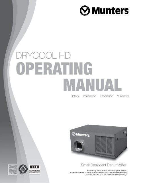
Protected by one or more of the following U.S. Patents.5435958; 5505769; 5423934; 5500402; 6375914;6557365; 6622508; 6711907;6875299; 7047751. U.S. and worldwide Patents Pending.
TABLEOF CONTENTS1 Installation............................................................................ 11.1 Ducting for Dehumidification................................... 1Supply Air Duct....................................................... 1Reactivation Air Duct............................................... 1Fresh Air Intake Duct............................................... 11.1.2 Installation in Basement.......................................... 21.1.3 Installation in Attic................................................... 31.1.4 Installation for Dehumidifying Only for aStand Alone Space.................................................. 31.2 Electrical Requirements........................................... 41.3 Condensate Removal.............................................. 41.4 External Humidistat................................................. 41.5 Optional UV Light ................................................... 42 Intended Application........................................................... 52.1 Specifications.......................................................... 53 Operation.............................................................................. 63.1 Humidity Control Adjustment.................................. 63.2 Fan / Filter Switch................................................... 64 Maintenance......................................................................... 64.1 Standard Filters....................................................... 64.2 High Efficiency Active Filters................................... 64.3 Germicidal UV Lights............................................... 65 Service ................................................................................ 75.1 Technical Description.............................................. 75.2 Troubleshooting....................................................... 75.3 Humidity Control..................................................... 86 Special Options.................................................................... 86.1 High Efficiency Active Filtration............................... 86.2 Germicidal UV Lights............................................... 86.2.1 UVC Lights Installation and Operation.................... 97 Warranty............................................................................. 11
1 Installation1.1 Ducting for DehumidificationThe DRYCOOL <strong>HD</strong> Dehumidifier uses a uniquearrangement of two air streams to accomplish the taskof providing cool dry air at high efficiencies. These area supply air stream and a reactivation air stream. Thesupply air stream is meant to dehumidify air for thespace being controlled. The reactivation air streamexpels the water vapor collected by the desiccantdehumidification wheel.Supply Air DuctGENERAL WARNINGS & CAUTIONSAll electrical work should only be performed by qualified electrical personnel. Repair to electricalcomponents by non-certified technician may result in personal injury and/or damage to the unit.Installation should be conducted by a qualified technician only and Munters and Munters affiliate are not responsiblefor injuries and /or damages caused by improper installation.CAUTIONMAKE SURE THE UNIT IS LEVEL.A 11.5" W x 12" H square inlet located on the same side asan 8” round outlet is the supply air intake for the unit. Thesquare inlet can be connected directly to the return air ductcoming from the central part of the structure.This duct should draw air from the central part of the structureand supply it to the isolated areas of the structure like smallerrooms. The ductwork of the existing heating system can beused to supply air to the structure. If the existing supplygoes to isolated areas of the structure, discharge the supplyof the DRYCOOL <strong>HD</strong> unit into the supply of the existingcentral system. DO NOT draw air directly from the kitchen,laundry, or basement. You may draw air from a basementthat is open to the structure. All flexible ductingconnected to the DRYCOOL <strong>HD</strong> unit should be UL listed.The supply outlet of the DRYCOOL <strong>HD</strong> is located onthe same side as the square supply inlet. A length of6 feet or more of acoustical flex ducting on the outletof the unit will reduce air noise from the blower. Alength of flexible ducting on all DRYCOOL <strong>HD</strong> ductconnections is recommended to reduce noise andvibration transmitted to rigid ductwork in the structure.Ducting the DRYCOOL <strong>HD</strong> as mentioned in sections 1.1requires consideration of the following points:Duct Sizing: For total duct lengths up to 25', use aminimum 8" diameter round or equivalent rectangular.For longer lengths, use a minimum 8" diameter or equivalent.Grills or diffusers on the duct ends must not excessivelyrestrict air flow.Isolated Areas: Effective dehumidification may requireducting be branched to isolated, stagnant areas.Use 8" or larger diameter branch ducting to each oftwo or three areas; use 4" or larger to each of four ormore areas.Connecting to existing HVAC systems: An optional 8"check damper can be installed to prevent reverse flowthrough the unit. If the DRYCOOL <strong>HD</strong> is ducted to thesupply of a high static air handler the check damper maybe placed in the unit supply duct.Ducting Reactivation AirA separate set of duct connections are provided for theDRYCOOL <strong>HD</strong> dehumidifier for the reactivation air. Thereactivation air is meant to convey the water vapor capturedby the desiccant wheel away from the unit and outsidethe structure.The reactivation outlet connection is an 8" round connectionlocated on the opposite side of the 12" W x 13.5" H squaresupply air inlet. For total duct lengths up to 25’, use aminimum 8” diameter round or equivalent rectangular. Theduct should be brought to an outside wall or louver so that“wet” reactivation air is expelled from the space and to theoutdoors. Use a conventional dryer vent with back draftdamper for penetrating the wall if infiltration is a concern.Ducting for Fresh AirFresh air can be brought into the structure by connectinga duct from outside to the DRYCOOL <strong>HD</strong> unit inlet and byturning on the fan switch or activating the humidity control.The fresh air duct must be connected to the return air ductof the central air system upstream of the DRYCOOL <strong>HD</strong>Dehumidifier.1
Additional considerations are as follows:1.2.3.4.Outside air is filtered before entering the building.Outside air will be dehumidified before entering if theunit is running in dehumidification mode.Drawing air from outside and blowing inside aids inslightly pressurizing the structure. This helps preventdirty and humid air from entering elsewhere.Adequate exhaust fans are recommended in the bathrooms and kitchen.In cold climates or areas where the outdoor dew point is lowat times, ventilation can be used to dehumidify the structure.This is accomplished by bringing the dry, low dew pointair into the structure during these times. This approach isoften more economical than running the dehumidifier toremove excess moisture from the structure.In cold climates, it is critical to adequately ventilate toreduce the inside moisture content to avoid moistureaccumulating in the wall cavities. For example; in a housethat experiences condensation on the interior surface ofthe windows during the winter, increasing the amount ofventilation will often cure the problem.The DRYCOOL <strong>HD</strong> is designed to move 250 cfm. Aninsulated 8"diameter duct is generally sufficient to provideup to 75 cfm of outside air. Remaining 175 cfm of return aircan be mixed with this fresh air and ducted into the supplyintake of the DRYCOOL <strong>HD</strong>.1.1.4 Installation in Basement or Crawl Space with Existing Forced Air HVACAHUAHUConditioned Unventilated Basement InstallationVentilated Unconditioned Basement InstallationIf the existing system has multiple returns, select one todisconnect from the existing forced air system and use itfor the dedicated DRYCOOL <strong>HD</strong> return. Always select areturn from a central location in the structure in an area thatis always open to the rest of the structure.Do not use a return from a room that often may have itsdoor closed. If the structure in which the DRYCOOL <strong>HD</strong>is to be installed has an existing forced air HVAC system,utilize the HVAC system to make the DRYCOOL <strong>HD</strong> unitinstallation easier.Basement Installation: Install a separate 8" return duct forthe DRYCOOL <strong>HD</strong> in a central area of the structure. Ductthe supply of the DRYCOOL <strong>HD</strong> to an 8" x 8" x 8" tee/damper that is 20% open to the basement. Duct the otherside of the tee to the air supply of the existing HVAC system.Connect a 8" reactivation duct to the reactivation outlet toexpel moist air outside the basement.Crawl Space Installation: Install a separate return for theDRYCOOL <strong>HD</strong> in a central area of the structure. Duct thesupply of the DRYCOOL <strong>HD</strong> to an 8" x 8" x 8" tee/damperthat is 20% open to the crawl space. Duct the other sideof the tee to the air supply of the existing HVAC system.Connect an 8" reactivation duct to the reactivation outletto expel moist air outside the basement.2
1.1.5 Installation in an Attic with a Existing Forced Air HVACAHUAttic InstallationALWAYS install a secondary catch pan with a drain or float interrupt for condensate under the DRYCOOL <strong>HD</strong> in an attic.Locate a separate return for the DRYCOOL <strong>HD</strong> in a central area of the structure or draw air from return ductwork. Ductthe supply side of the DRYCOOL <strong>HD</strong> to the air supply of the existing HVAC system. Connect an 8" reactivation duct tothe reactivation outlet to expel this “moist” air outside the basement.1.1.6. Installation for Dehumidifying for a Stand Alone SpaceOne of the benefits of a DRYCOOL <strong>HD</strong> is the deliveryof dehumidified air to the space at approximately thesame temperature that enters the device. This allowsan owner to simplify the installation for applications orinstances where it is desired to maintain humidity levelsin one open space. In these applications the return airfrom the space is connected directly to the unit and thedehumidified air can be delivered directly back into theroom without the need to mix it with cold air coming from acentral air conditioning system.HUMIDISTATRETURN AIRSUPPLY OUTREACT OUTLETREACT INLETIf the space is a large common room and is open toother adjacent rooms, using the DRYCOOL <strong>HD</strong> canhave the effect of providing dehumidification to muchlarger connected areas or even a small structure. Watervapor diffuses from areas of high vapor pressure toareas of low vapor pressure. When large spaces aredehumidified with a DRYCOOL <strong>HD</strong>, areas of low vaporpressure are created and will induce water vapor movementfrom other connected open rooms without the needfor ducting.The figure shows how the unit draws return air from thecommon space or a ventilated closet and discharges thedehumidified air back into the space.STAND ALONESPACECLOSET OR OTHERSTORAGE AREAThe DRYCOOL <strong>HD</strong> requires the mounting of theremote humidistat away from the discharge in anarea that is representative of the larger space. As with allof the installation configurations of a unit, the reactivationair still needs to be ducted to and from the outdoors asshown here.3
1.2 Electrical Requirements/Humidistat InstallationThe DRYCOOL <strong>HD</strong> plugs into a common grounded outleton a 15 Amp circuit. It draws between 6 and 7 Amps undernormal operating conditions. If used in a wet area, a groundfault interrupter protected circuit is required.If an extension cord is required, it must have a minimum of16 gauge conductors if less than 25 feet long and 14 gaugeif greater than 25 feet long.Install the remote humidistat in a central area of thestructure where it will sense the relative humidity ofthe structure accurately. Do not install the humidistatwhere it may not accurately sense the relative humiditysuch as near HVAC supply registers, near exterior doors,or near a pool or spa. The installer must supply thewiring between the dehumidifier unit and the humidistat.Be sure to safely route the control wires to prevent damageduring installation. Be careful not to cross the wires whenconnecting the DRYCOOL <strong>HD</strong> and the humidistat ordamage to the transformer may result.The humidistat of the DRYCOOL <strong>HD</strong> is powered by a lowvoltage circuit and must NEVER contact or be connectedto a high voltage circuit. The control wires leaving the unitand the humidistat are color coded to prevent confusion.Be sure to consult the electrical schematic in this manualor on the front panel of the DRYCOOL <strong>HD</strong> before makingthe control connections.1.3 Condensate RemovalCAUTION The DRYCOOL <strong>HD</strong> removes largeamounts of moisture from the air and the devicemust be connected to a drain line that will carryaway the excess water. A trap in the drain line isstrongly recommended.The drain line should be connected to the 3/4” female pipethread adaptor on the front of the DRYCOOL <strong>HD</strong>.Care should be taken to install the drain line with acontinuous slop of 1" per 10' to assure proper waterremoval.An optional condensate pump may be installed if a lift isrequired to dispose of the condensate. The condensatepump kit can be ordered direct from the factory.CAUTION For additional safety, Munters alwaysrecommends that a catch pan with front switch beplaced under the DRYCOOL <strong>HD</strong>.An optional condensate pump may be installed if a lift isrequired to dispose of the condensate. The condensatepump kit can be ordered direct from the factory.1.4 Installation in a Structure with NoExisting Forced Air HVACWhen installing the DRYCOOL <strong>HD</strong> in a structure thatdoes not have a forced air HVAC system, a singlereturn for the DRYCOOL <strong>HD</strong> should be installed incentral open area of the structure. DO NOT locate thereturn in a bathroom or a kitchen. The supply of the unitshould be located in the remote areas of the structure(such as bedrooms, den, etc...). By ducting this way theair inside the structure will circulate through the DRYCOOL<strong>HD</strong> to be filtered and dehumidified. 4” diameter duct isrecommended for branches to the bedrooms, 6” diameterduct is recommended for branches to larger areas. Connectan 8” reactivation duct to the reactivation outlet to expelmoist air outside the space.1.5 Optional UV LightSafety Notices: Improper installation, adjustment, alteration,service, maintenance, or use can cause fire, electricalshock, or other conditions which may cause personalinjury or property damage. Consult your local authorizeddealer or Munters Corporation for additional informationor assistance.WARNING Before performing maintenanceor service on fixture, ensure unit is unplugged.Electrical shock can cause injury or death.• Never expose eyes or skin to UVC light from anysource. Wear gloves, face shield/glasses (perANSI Z87.1) and cover all exposed skin.• Do not touch Emitter glass without gloves.Damage to Emitter may result. Oil fromfingerprints will permanently etch glass ofEmitter. If necessary, clean Emitter usingoptional cleaning kit.• Voltages outside of the range designed for theunit will void the warranty and do permanentdamage to the entire unit.• Emitter contains a small quantity of mercury. Ifan Emitter breaks, clean and dispose with care.Note: Ensure that emitter is installed before power isapplied. Installing emitter after the power has been appliedwill trigger the “end of lamp life circuit” and emitter will failto light! If this happens, shut off power for 10 minutes andthen turn power back on. Emitter will then light.4
1.2.3.4.Disconnect power from the DRYCOOL <strong>HD</strong> unitRemove installation hole plug. This black plastic plugis located on the same end of the unit as the controlpanel and is above the condensate drain outlet.Insert support wire.Insert emitter into hole, ensuring that emitter ceramicend rests on support wire’s hook and that emitter collaris set firmly against hole perimeter.5.6.7.Cut spine in order to accommodate the support wire.Reinstall the spine pieces.Attach emitter extension cord to power supply, andplug power supply into the outlet on the DRYCOOL <strong>HD</strong>labeled “UV Light”.Power can now be reconnected to the MuntersDRYCOOL <strong>HD</strong> unit.2 Intended ApplicationThe DRYCOOL <strong>HD</strong> Dehumidifier is intended for installationin spaces that experience short or long term highhumidity conditions. Use of the DRYCOOL <strong>HD</strong> in poolareas will void warranty. In order to efficiently controlhumidity levels, the area in which the dehumidifier is tobe placed must be free of water intrusion or excessivefresh air infiltration. Before installation of the DRYCOOL<strong>HD</strong>, water intrusion or excess air infiltration shouldbe addressed.8”REACT INLETDO NOT place the DRYCOOL <strong>HD</strong> directly on structuralmembers.A secondary drain pan MUST be placed under the unit.The DRYCOOL <strong>HD</strong> should be located near the existing airhandling system to minimize the required ductwork. Thecontrols for the DRYCOOL <strong>HD</strong> are remote from the unit andmust be located in the space that is to be conditioned. Thecontrols are low voltage (24 volt) and should be connectedto the DRYCOOL <strong>HD</strong> with low voltage thermostat wire.8”SUPPLY OUTCOND. COILSQUARE TOROUND(OPTIONAL)If fresh air ventilation is desired, thought should be given tothe location for the fresh air ducting. An 8” round insulatedduct will have to be installed on the DRYCOOL <strong>HD</strong>and run to the outside of the structure to bring in fresh air.The unit is not meant to condition more than 75cfm of outside air. Consult local codes for necessarydistances from exhaust ports when installing fresh airreturn.SQUARE TOROUND(OPTIONAL)OPTIONALO.A. CONNECTIONDRAINEVAP.ELECT.UNIT DETAIL8”REACT OUTLETROUND OUTDO NOT use the DRYCOOL <strong>HD</strong> as a bench or table.2.1 SpecificationMODELElectricalCapacityEfficiency<strong>Operating</strong> Temp.Air FlowRefrigerantUnit SizeUnit WeightShipping WeightDRYCOOL <strong>HD</strong>115 / 60 / 1, 7 A @ AHAM120 Pints/day @ 80 °F DB / 60% RH3.3 L/kW50°FF – 95°FF250 CFM without external restrictionsRefrigerant Charge 28 oz. R41024 L x 36 W x 16.5 H95 lbs.110 lbs.5
3 OperationThe DRYCOOL <strong>HD</strong> can be equipped with variousaccessories to enhance its operation. A remote humidistatmust be used with the unit.3.1 Humidity Control AdjustmentSet the humidity control to the desired humidity level forthe structure. Turning the knob clockwise on the humidistatresults in a drier setting.The dehumidifier will run continuously until the relativehumidity (RH) is reduced to the humidity control dialsetting. Setting the humidity control to lower RH levels willNOT increase the unit’s dehumidification rate; the unit willsimply run longer to reduce the area’s RH to the setting.The DRYCOOL <strong>HD</strong> (and refrigerant based dehumidifiers ingeneral) will reduce a conditioned space’s RH to a lowerlevel. Settings below 40% are not recommended.3.2 Fan/Filter SwitchTurning ON the fan/filter switch on the side of the unit willcause the DRYCOOL <strong>HD</strong> internal fan to run continuously,whether the unit is dehumidifying or not.This function is desirable if the unit is used for air circulationand filtration to achieve maximum indoor air quality. Whenthe switch is ON; air will be constantly filtered through theunit and circulated throughout the house. When the switchis OFF; the fan will operate only when the humidity controlcalls for dehumidification.Along with either the high efficiency filter and/or theGermicidal UVC, the DRYCOOL <strong>HD</strong> can be used to performtotal Indoor Air Quality control for your structure.4 Maintenance4.1 Standard Air FilterThe DRYCOOL <strong>HD</strong> is equipped with an air filter. This filtershould be checked every three months. <strong>Operating</strong> the unitwith a dirty filter will reduce dehumidifier capacity andefficiency and may cause the compressor to cycle off andon unnecessarily based on, or due to, high level pressureTo access the air filter, slide the filter out of the side of theunit. The filter can generally be vacuumed clean severaltimes before needing replacement. Replacement filters canbe purchased locally. DO NOT operate the unit without afilter. The heat exchange coils inside the unit could becomeclogged and require disassembly to clean.4.3 Germicidal UVC LightsContinuously operated emitters need to be replacedannually to maintain design output. As a note, emitter on/off cycles should be minimized in order to maximize emitterlife.No more than an ordinary light bulb - SteriLight’s uniqueEmitters are simply changed once a year. SteriLight isvirtually maintenance-free between change outs!CAUTION Do not look at UVC lights whenoperating without adequate eye protection. UVCcan cause damage to unprotected eyes.4.2 High Efficiency Air FilterAn optional high efficiency active electrostatic filteris available for the DRYCOOL <strong>HD</strong>. This filter is ratedas 90%-95% efficient by the ASHRAE Dust Spot testmethod 52-76. In addition Munters E-Filter, removes otherparticles not measured by the ASHRAE Dust Spot Test.This filter is able to remove allergy causing particles fromthe airstream. Check the high efficiency air filter every 4months and replace if necessary. Do not attempt to cleanthe high efficiency filter. It should be replaced when itbecomes restrictive.The UVC Air Purification System6
5 Service5.1 Technical DescriptionThe DRYCOOL <strong>HD</strong> uses a refrigeration system similar to anair conditioner’s to remove heat and moisture from incomingair. In addition a dehumidification wheel downstream ofthe evaporator coil removes additional moisture from theairstream in a vapor state.COMPRESSORTXVRefrigeration System of DRYCOOL <strong>HD</strong>TXEVAPORATORFILTER/DRIERCONDENSERHot, high pressure refrigerant gas is routed fromthe compressor to the condenser coil. The heatfrom the condenser is used to reactivate thedesiccant dehumidification wheel. The heat applied to thedesiccant dehumidification wheel allows water to evaporateoff the wheel and be discharged by the reactivation fan.The reactivation air needs to be ducted to the outside.The refrigerant is cooled and condensed by giving up itsheat to the air that is about to be discharged from theunit. The refrigerant liquid then passes through a filter/drier and capillary tubing which cause the refrigerantpressure and temperature to drop. It next enters theevaporator coil where it absorbs heat from the incomingair and evaporates. The compressor evacuates the coolrefrigerant gas from the accumulator and compressesit to a high pressure and temperature to repeatthe process.5.2 TroubleshootingFan runs with fan switch and ventilation timer OFF, butcompressor cycles on & off.1.2.3.4.5.Low ambient temperature and/or humidity causing unitto cycle through defrost mode.Dirty air filter(s) or air flow restricted.Defrost thermostat defective .Defective compressor overload.Defective compressor.Fan does not run with fan switch in either position. Fandoes not run with ventilation timer activated. Compressorruns briefly but cycles on & off with humidity control turnedto ON.1.2.3.4.Loose connection in fan circuit.Obstruction prevents fan impeller rotation.Defective fan.Defective fan relay.Evaporator coil frosted continuously, low dehumidifyingcapacity.1.2.3.Dirty air filter(s) or air flow restricted.Unit defrost thermostat loose or defective.Low refrigerant charge.Emitter does not light1.2.3.4.5.Turn off power for 10 minutes and then turn powerback on.Check line voltageCheck wiring to emitterReplace emitterReplace power supplyLow Output or visibly weak light1.2.3.Replace emitter with new unitCheck line voltageCheck wiring to emitterRed/Orange light1. Check ambient temperature, light will not operateproperly below 35°F2. Follow actions for “Low Output”7
CAUTION Servicing the DRYCOOL <strong>HD</strong> with its highpressure refrigerant system and high voltage circuitrypresents a health hazard which could result in death,serious bodily injury, and/or property damage. Onlyqualified service people should service this unit.5.3 Humidity ControlThe humidistat control is an adjustable switch that closeswhen the relative humidity of the air in which it is locatedrises to the dial set point. If the DRYCOOL <strong>HD</strong> does not run,try turning the humidity control clockwise until it reachesthe stop and the knob pointer points at “on.” If it still doesnot run, remove the stop screw from the panel and turn theknob farther. If it then runs, the humidity control is out ofcalibration.6 Options6.1 Active High Efficiency Air FilterAn optional active electrostatic high efficiency air filter isavailable for the DRYCOOL <strong>HD</strong>. This filter is rated 90%-95% efficient by ASHRAE Dust Spot Test Method 52-76.This filter is much more efficient than the standard airfilter and is able to catch much smaller particles that canaggravate allergies.Particle Size Typical Contaminant Capture Efficiency3–10 Microns Pollen, mold, dust mites, hair spray 99%1–3 Microns Auto emissions, lead dust, large bacteria 98.6%.3–1 Micron Smoke (tobacco, cooking), small bacteria, finedust, paint pigmentsVOCs (odors, offgasses including formeldehydefrom carpets, furniture, and cleaningproducts)Munters Active Electrostatic FilterThe high efficiency air filter is an electrostatic filter thatuses state of the art technology to clean air to a MERV 13rating. In addition, the active electrostatic capability of thefilter removes other particles that can not be removed bystandard passive filters.Particle Size Typical Contaminant Capture Efficiency3–10 Microns Pollen, mold, dust mites, hair spray 99%1–3 Microns Auto emissions, lead dust, large bacteria Not Effective97%40%6.2 Germicidal UVCAn optional active germicidal UVC system can beprovided with the Munters DRYCOOL <strong>HD</strong>. UVC is atype of ultraviolet (UVC) energy in the 260-nanometerfrequency. The “C” wavelength is the most germicidalin the UVC spectrum. The “C” wavelength targets theDNA of microorganisms, causing cell death or makingreplication impossible. The UVC energy kills or inactivatesmicrobes, eradicating surface and airborne mold, as wellas viruses and bacteria.UVC is not an air filter. Rather it’s a UVC air purificationsystem, based on Steril-Aire’s multi-patented technology,used in thousands of schools, hospitals, and governmentand commercial buildings. This same proven technology isnow available for the structure.The UVC air purification system then uses germicidal actionto destroy the mold, bacteria and viruses that grow andcirculate in the air, before they travel around your space totrigger allergic reactions or spread disease.Benefits of UVC Air Purification Systems:• Kill the mold and bacteria that grow in your A/C system.• Reduce or eliminate allergies, allergy asthma and othermaladies caused by mold and bacteria.• Destroy circulating cold and flu viruses and otherinfectious microbes..3–1 Micron Smoke (tobacco, cooking), small bacteria, finedust, paint pigmentsVOCs (odors, offgasses including formeldehydefrom carpets, furniture, and cleaningproducts)Conventional Passive FiltersNot EffectiveNot Effective• Increase your A/C system’s useful life, reduce costlycleanings and save energy.• Make indoor air smell as fresh as the freshest dayoutdoors with an UVC air purification system.8OPTIONAL PARTS LIST: DRYCOOL <strong>HD</strong> Indoor Air Quality
6.2.2 UVC Installation and Operation and Operation InstructionsNOTE:Readthisentireinstructionsheetbeforestartingtheinstallation. IMPORTANT CONSIDERATIONSImproper installation, adjustment, alteration, service,maintenance, or use can cause fire, electrical shock, orother conditions which may cause personal injury orproperty damage. Consult your supplier or Steril-Aire forinformation or assistance. In regards to the statementsbelow, understand the signal words DANGER,WARNING, or CAUTION. These words are universally used for overall safety. DANGER identifies the mostserious hazards which will result in severe personalinjury or death. WARNING signifies hazards whichImproper installation, adjustment, alteration, service,could result in personal injury or death. CAUTION ismaintenance, or use can cause fire, electrical shock, orused to identify unsafe practices resulting in minorother conditions which may cause personal injury orpersonal injury or product and property damage.property damage. Consult your supplier or Steril-Aire forinformationWARNING: Beforeor assistance.performingIn regardsmaintenanceto the statementsorservicebelow,onunderstandfixture, ensurethe signalunitwordsis unplugged.DANGER,ElectricalWARNING,shockor CAUTION.can causeTheseinjury orwordsdeath.are universallyused for overall safety. DANGER identifies the mostCAUTIONS:serious hazards which will result in severe personalinjury or death. WARNING signifies hazards which Never expose eyes or skin to UVC light fromcould result in personal injury or death. CAUTION isany source. Wear gloves, faceused toshield/glassesidentify unsafe(perpracticesANSIresultingZ87.1) andin minorcover allpersonalexposedinjury orskin.product and property damage.Component ACONTENTSPTAC115 V, 208/230 VPatents 5,334,347, 5,817,276, 5,866,076, 6,245,293, 6,267,924, 6,280,686,6,313,470, 6,372,186, 6,423,882, 6,500,267, 6,589,476, 6,627,000 & others pendingMadeinUSAInstallation and Operation InstructionsNOTE:Readthisentireinstructionsheetbeforestartingtheinstallation.WARNING: Before performing maintenance orservice on fixture, ensure unit is unplugged.Electrical shock can cause injury or death. Power supply – HO, 1 Emitter lead, 115 V or 208/230 VCAUTIONS:Emitter – RGTS 7.5-24” HO Recessed NeverEmitterexposeholdereyesassemblyor skin to UVC light fromany source. Wear gloves, faceshield/glasses (per ANSI Z87.1) and cover allexposed skin.Power supply – HO, 1 Emitter lead, 115 V or 208/230 VEmitter – RGTS 7.5-24” HORecessed Emitter holder assemblyIMPORTANT CONSIDERATIONSCONTENTS Do not touch Emitter glass without gloves.Damage Patents 5,334,347, to Emitter 5,817,276, may 5,866,076, result. 6,245,293, Oil 6,267,924, from 6,280,686,6,313,470, fingerprints 6,372,186, 6,423,882, will permanently 6,500,267, 6,589,476, etch 6,627,000 glass & others of pendingEmitter and weaken structure. If necessary, MadeinUSAclean Emitter using a Steril-Aire cleaning kit (isopropyl alcohol and a lint-free wipe maybe substituted). Voltages outside of the range designed forthe unit will void the warranty and dopermanent damage to the entire unit. Do not touch Emitter glass without gloves. EmitterDamagecontainsto Emittera smallmayquantityresult.ofOilmercury.fromIf an Emitter breaks, clean and dispose offingerprints will permanently etch glass ofwith care.Emitter and weaken structure. If necessary, UVCcleanenergyEmittermayusingcauseadamageSteril-Aireto nonmetalliccleaning kit(isopropylcomponentsalcohol andexcepta lint-freefor UV-ratedwipe mayandHVAC-stylebe substituted).drain pans. Select mountinglocations that prevent exposure to Voltages outside of the range designed forvulnerable components. If mountingthe unit will void the warranty and dolocations are limited, such components shallpermanent damage to the entire unit.be protected with UV resistant material such Emitter contains a small quantity of mercury.as aluminum foil, aluminum duct tape,metallicIf an Emittershields,breaks,etc.clean and dispose ofwith care. UVC energy may cause damage to nonmetalliccomponents except for UV-rated andHVAC-style drain pans. Select mountinglocations that prevent exposure tovulnerable components. If mountinglocations are limited, such components shallbe protected with UV resistant material suchas aluminum foil, aluminum duct tape,metallic shields, etc.Component BPTAC115 V, 208/230 V #8, ½” self-drilling pan head screw (6) Extension cord (optional)Component AComponent B9 #8, ½” self-drilling pan head screw (6)
NOTE:ENSURETHATEMITTERISINSTALLEDBEFOREPOWERISAPPLIED.INSTALLINGEMITTERAFTERPOWERHASBEENAPPLIEDWILLTRIGGERTHE“ENDOFLAMPLIFECIRCUIT”ANDTHEEMITTERWILLFAILTOLIGHT!IFTHISHAPPENS,SHUTOFFPOWERFOR10MINUTESANDTHENTURNPOWERBACKON.EMITTERWILLTHENLIGHT.1. Disconnect power from PTAC unit.2. Remove outer cover of PTAC unit.3. Determine location of Emitter (Many types of PTACunits have a removable shroud/heating coilassembly that may adequately accommodate theEmitter.) The Emitter shall:o Be at least 1” away from the heating coil.o Not make contact with the blower.o Provide direct light onto the cooling coil anddrain pan.o Not be directly visible from outside of thePTAC unit. A baffle may be installed toprovide any needed light blockage.o Be supported/powered through a side panelhole (to be drilled in next steps).INSTALLATION & OPERATIONPhoto 24. Determine a flat-surfaced location for power supplyand Emitter hole location that will be in reach ofeach other. Also account for power source reach.5. Drill 1-1/4” hole on a panel to accommodatecomponent B of Emitter holder assembly andsecure B with screws.6. Slide Emitter partially through B.7. Slide component A (collared end first) onto powersupply’s cord or extension cord and install cord ontoEmitter pins (see photo 1).8. Slide Emitter and comp. A through B, and twist andlock A under B’s tabs (see photo 2).9. Mount the power supply with the provided screws atthe pre-determined location.10. Complete all power connections.11. Reconnect power to the PTAC. The Emitter shouldemit a bright blue hue, indicating that it is workingproperly.12. Replace outer cover of PTAC.Photo 1Emitters need to be periodically replaced to maintaindesign output. The change-out basis depends upon theapplication, number of times switched on/off per day,and the hours of operation. Emitters are to be replacedwhen output falls to 50% of initial output (or as specified)SymptomEmitter TM Does Not LightLow Output (RadiometerReading) orVisibly Weak LightRed/Orange LightMAINTENANCETROUBLESHOOTINGby actual radiometer measurements. A Steril-Aire UVCRadiometer Kit may be used for such measurements. Ifa radiometer is unavailable, Emitters should be replacedafter 9,000 hours of use.Recommended Action(in order of priority)1. Turn off power for 10 minutes, and then turn power back on.2. Replace Emitter with new unit (recommended once per year).3. Check line voltage.4. Check wiring to Emitter.5. Replace power supply.1. Replace Emitter with new unit.2. Check line voltage.3. Check wiring to Emitter.1. Check ambient temperature. If temp. 35°F, Emitter too cold to operate properly.2. If ambient temp. is in excess of 35°F, follow actions for the Low Output symptom.____________________________________________________________________________________________________________1-800-2-STERIL www.steril-aire.com.Steril-Aire, Inc. cannot and does not guarantee that all organisms will be inactivated or killed or that use of Steril-Aire, Inc.10UVC Emitters will prevent infection or illness.
PARTITEM DESCRIPTIONNO.0001 <strong>DryCool</strong> Mini - Base Unit 120 PPD, 115/60/1- includes premier Honeywell humidistat and square-to-round adapter packageOPTIONS0500 Digital Combination Ventilation/Humidistat w/LED1001 UV Light - Complete Package1002 UV Light - Replacement Lamp Only1003 UV Light - Replacement Power Pack Only2001 Polarized - Media Air Cleaner20032024SystemPolarized - Media - Replacement Media (3 pack)Polarized - Media - Replacement Media (24 pack)7 Limited WarrantyYour Munters DRYCOOL <strong>HD</strong> Dehumidifier is expressly warranted for a period of one (1) year from date of purchase. This warrantyextends to the original end user and may not be assigned to or transferred. Munters warrants that for one (1) year after the date of originalpurchase the DRYCOOL <strong>HD</strong> Dehumidifier will operate free from any defects in materials and workmanship. Munters exclusive obligationunder this warranty will be to supply, without charge, a replacement part for the dehumidifier which is found to be defective within a one(1) year period from the date of purchase and which is returned not later than thirty (30) days after said one (1) year period to Munters<strong>DryCool</strong>, Selma, TX together with proof of purchase of the dehumidifier.THIS WARRANTY SHALL NOT OBLIGATE MUNTERS CORPORATION FOR ANY LABOR COSTS AND SHALL NOT APPLY TO DEFECTS INWORKMANSHIP OR MATERIALS FURNISHED BY YOUR INSTALLER AS CONTRACTED TO DEFECTS IN THE DEHUMIDIFIER ITSELF.IMPLIED WARRANTIES OF MERCHANTABILITY OR FITNESS FOR A PARTICULAR PURPOSE SHALL BE LIMITED IN DURATION TO THEAFORESAID ONE YEAR PERIOD. MUNTERS CORPORATION’S LIABILITY FOR INCIDENTAL OR CONSEQUENTIAL DAMAGES, OTHERTHAN DAMAGES FOR PERSONAL INJURIES, RESULTING FROM ANY BREACH OF AFORESAID IMPLIED WARRANTIES OR THEABOVE LIMITED WARRANTY IS EXPRESSLY EXCLUDED. THIS LIMITED WARRANTY IS VOID IF DEFECT(S) RESULT FROM FAILURETO HAVE THIS UNIT INSTALLED BY A QUALIFIED HEATING AND AIR CONDITIONING CONTRACTOR. IF THE LIMITED WARRANTY ISVOID DUE TO FAILURE TO USE A QUALIFIED CONTRACTOR, ALL DISCLAIMERS OF IMPLIED WARRANTIES SHALL BE EFFECTIVEUPON INSTALLATION.Some states do not allow limitations on how long an implied warranty lasts or the exclusion of limitation of incidental or consequentialdamages, so the above exclusions or limitations may not apply to you.This warranty gives you specific legal rights and you may also have other rights which vary from state to state.CAUTION ELECTRICAL SHOCK HAZARD: Electrical power must be present to perform some tests. These tests should beperformed by a qualified service person.E-mail: drycoolinfo@munters.com or Call: 800.229.8557Visit us online at www.munters.us11
Munters is a global leader in energy efficient air treatment solutions.Munters manufactures engineered products that can economically control humidity and temperature,provide energy recovery, and/or utilize direct or indirect evaporative cooling for comfort, process andenvironmental protection. With permanent or temporary solutions, Munters offers a wide variety of optionsto meet specific climate, application and budget requirements. Munters has net sales approaching $1 billionUSD with more than 20 manufacturing facilities across the globe and sales offices in over 30 countries.Munters employs approximately 4,300 people worldwide.For more information see www.munters.us


