Operating Manual_DryCool HD.pdf - HTS
Operating Manual_DryCool HD.pdf - HTS
Operating Manual_DryCool HD.pdf - HTS

Create successful ePaper yourself
Turn your PDF publications into a flip-book with our unique Google optimized e-Paper software.
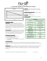
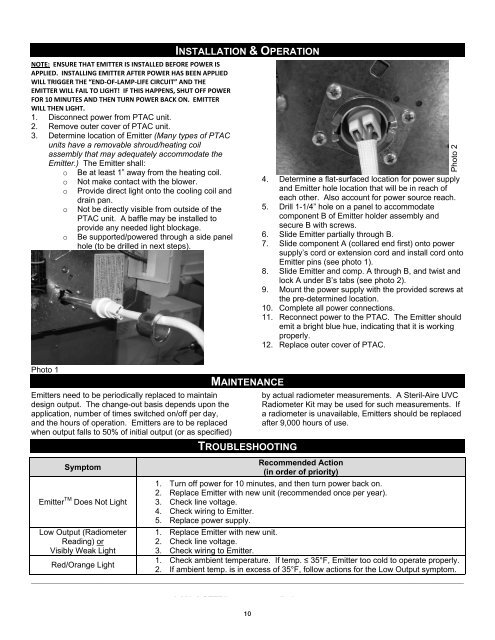
NOTE:ENSURETHATEMITTERISINSTALLEDBEFOREPOWERISAPPLIED.INSTALLINGEMITTERAFTERPOWERHASBEENAPPLIEDWILLTRIGGERTHE“ENDOFLAMPLIFECIRCUIT”ANDTHEEMITTERWILLFAILTOLIGHT!IFTHISHAPPENS,SHUTOFFPOWERFOR10MINUTESANDTHENTURNPOWERBACKON.EMITTERWILLTHENLIGHT.1. Disconnect power from PTAC unit.2. Remove outer cover of PTAC unit.3. Determine location of Emitter (Many types of PTACunits have a removable shroud/heating coilassembly that may adequately accommodate theEmitter.) The Emitter shall:o Be at least 1” away from the heating coil.o Not make contact with the blower.o Provide direct light onto the cooling coil anddrain pan.o Not be directly visible from outside of thePTAC unit. A baffle may be installed toprovide any needed light blockage.o Be supported/powered through a side panelhole (to be drilled in next steps).INSTALLATION & OPERATIONPhoto 24. Determine a flat-surfaced location for power supplyand Emitter hole location that will be in reach ofeach other. Also account for power source reach.5. Drill 1-1/4” hole on a panel to accommodatecomponent B of Emitter holder assembly andsecure B with screws.6. Slide Emitter partially through B.7. Slide component A (collared end first) onto powersupply’s cord or extension cord and install cord ontoEmitter pins (see photo 1).8. Slide Emitter and comp. A through B, and twist andlock A under B’s tabs (see photo 2).9. Mount the power supply with the provided screws atthe pre-determined location.10. Complete all power connections.11. Reconnect power to the PTAC. The Emitter shouldemit a bright blue hue, indicating that it is workingproperly.12. Replace outer cover of PTAC.Photo 1Emitters need to be periodically replaced to maintaindesign output. The change-out basis depends upon theapplication, number of times switched on/off per day,and the hours of operation. Emitters are to be replacedwhen output falls to 50% of initial output (or as specified)SymptomEmitter TM Does Not LightLow Output (RadiometerReading) orVisibly Weak LightRed/Orange LightMAINTENANCETROUBLESHOOTINGby actual radiometer measurements. A Steril-Aire UVCRadiometer Kit may be used for such measurements. Ifa radiometer is unavailable, Emitters should be replacedafter 9,000 hours of use.Recommended Action(in order of priority)1. Turn off power for 10 minutes, and then turn power back on.2. Replace Emitter with new unit (recommended once per year).3. Check line voltage.4. Check wiring to Emitter.5. Replace power supply.1. Replace Emitter with new unit.2. Check line voltage.3. Check wiring to Emitter.1. Check ambient temperature. If temp. 35°F, Emitter too cold to operate properly.2. If ambient temp. is in excess of 35°F, follow actions for the Low Output symptom.____________________________________________________________________________________________________________1-800-2-STERIL www.steril-aire.com.Steril-Aire, Inc. cannot and does not guarantee that all organisms will be inactivated or killed or that use of Steril-Aire, Inc.10UVC Emitters will prevent infection or illness.