RAYPAK REPLACEMENT INSTRUCTIONS - Pool Supply Unlimited
RAYPAK REPLACEMENT INSTRUCTIONS - Pool Supply Unlimited
RAYPAK REPLACEMENT INSTRUCTIONS - Pool Supply Unlimited

Create successful ePaper yourself
Turn your PDF publications into a flip-book with our unique Google optimized e-Paper software.
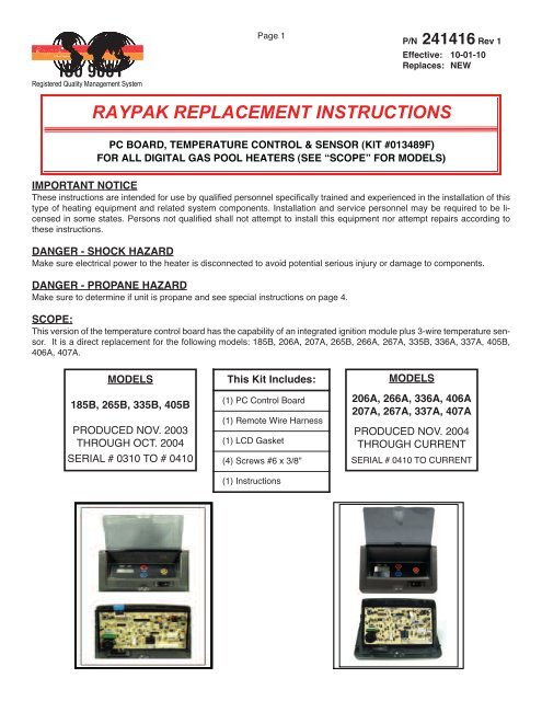
Page 1P/N 241416 Rev 1Effective: 10-01-10Replaces: NEW<strong>RAYPAK</strong> <strong>REPLACEMENT</strong> <strong>INSTRUCTIONS</strong>PC BOARD, TEMPERATURE CONTROL & SENSOR (KIT #013489F)FOR ALL DIGITAL GAS POOL HEATERS (SEE “SCOPE” FOR MODELS)IMPORTANT NOTICEThese instructions are intended for use by qualified personnel specifically trained and experienced in the installation of thistype of heating equipment and related system components. Installation and service personnel may be required to be licensedin some states. Persons not qualified shall not attempt to install this equipment nor attempt repairs according tothese instructions.DANGER - SHOCK HAZARDMake sure electrical power to the heater is disconnected to avoid potential serious injury or damage to components.DANGER - PROPANE HAZARDMake sure to determine if unit is propane and see special instructions on page 4.SCOPE:This version of the temperature control board has the capability of an integrated ignition module plus 3-wire temperature sensor.It is a direct replacement for the following models: 185B, 206A, 207A, 265B, 266A, 267A, 335B, 336A, 337A, 405B,406A, 407A.MODELS185B, 265B, 335B, 405BPRODUCED NOV. 2003THROUGH OCT. 2004SERIAL # 0310 TO # 0410This Kit Includes:(1) PC Control Board(1) Remote Wire Harness(1) LCD Gasket(4) Screws #6 x 3/8”(1) InstructionsMODELS206A, 266A, 336A, 406A207A, 267A, 337A, 407APRODUCED NOV. 2004THROUGH CURRENTSERIAL # 0410 TO CURRENT
ACCESSING THE CONTROL BOARDPage 2P/N 241416 Rev 1Effective: 10-01-10Replaces: NEW1. Turn off the power to the heater.2. Turn off the gas to the heater.3. B-Series: Remove front door by removingthe 4 door panel screws shown in Fig. 1 andFig. 2.4. A-Series: Remove front door by removingthe large door screw in front of unit asshown in Fig. 1.5. Remove the four screws on the side of controlpanel. See Fig. 3 and Fig. 4.6. Lay control panel forward toward you to accessthe back of the temperature controlboard.REMOVE THESESCREWS FOR B - SeriesLARGEDOORSCREWFig. 2Close-upFig. 1For A-SeriesREMOVE THESE SCREWSFig. 3Fig. 4
Page 3P/N 241416 Rev 1Effective: 10-01-10Replaces: NEWREMOVING THE CIRCUIT BOARDMake sure the power and gas are off.1. Unplug all connectors from old circuit board. SeeFig. 5.2. Unplug keypad ribbon from old circuit board.3. Remove screws as shown in Fig. 6.4. Remove old circuit board.UNPLUGALL CONNECTORSFig. 5REMOVE KEYBOARDRIBBONREMOVE MOUNTING SCREWSFig. 6
Page 4P/N 241416 Rev 1Effective: 10-01-10Replaces: NEWPROPANE HEATERS ONLY:PREPARE NEW <strong>REPLACEMENT</strong> CONTROL PCB FOR INSTALLATION1. Locate the proper propane tab on the board as shown in Fig. 7.2. Break off tab with pliers as shown in Fig. 8 & Fig. 9.Note:Requirements for Propane safety time vary byarea. Check your local and state code regulationsto determine whether your requiredPropane safety time is 15 seconds or 90 seconds.15-SecondSafety TimeFig. 790-SecondSafety TimePROPANETABSBROKEN TABFig. 8(90-SecondSafety Time Shown)Fig. 9(90-Second Safety Time Shown)
Page 5P/N 241416 Rev 1Effective: 10-01-10Replaces: NEWMODELS 185B, 265B, 335B & 405B, Low NOx ONLY:PREPARE NEW <strong>REPLACEMENT</strong> CONTROL PCB FOR INSTALLATION1. DO NOT break tab See Fig. 10 and Fig. 11.2. No additional wiring or connections are necessary for Low NOx operation.DO NOTbreaktab.Fig. 10DO NOTbreaktab.Fig. 11
Page 6P/N 241416 Rev 1Effective: 10-01-10Replaces: NEWLow NOx MODELS 207A, 267A, 337A & 407A ONLY:PREPARE NEW <strong>REPLACEMENT</strong> CONTROL PCB FOR INSTALLATION1. Locate Low Nox tab and P-10 air switch terminal on the board asshown in Fig. 12 and Fig. 13.2. Use pliers to break off the tab shown in Fig. 14.3. Attach the wire from the air switch to the P-10 location shown in Fig. 15.Low NOxTABP-10TERMINALBREAKTABWIRE AIRSWITCHTO P-10HEREFig. 12Fig. 13BROKEN TABP–10 TERMINALFig. 14Fig. 15
Page 7P/N 241416 Rev 1Effective: 10-01-10Replaces: NEWGASKET & NEW CIRCUIT BOARD NEW BEZEL INSTALLATIONNote: Disregard window gasket installation if already present.1. Remove backing on gasket and install adhesive side on the controlpanel bezel as shown in Fig. 16 & Fig. 17.2. Re-assemble with new board to plastic bezel using the three mountingscrews as shown in Fig. 18.REMOVE BACKINGGASKETADHESIVE SIDE TOPLASTIC BEZELFig. 16CLEARWINDOWLAY BEZELDOWNRE-ASSEMBLE WITH NEW BOARDMOUNTING SCREWSFig. 17Fig. 18
Page 8P/N 241416 Rev 1Effective: 10-01-10Replaces: NEWDIGITAL THERMOSTAT CONTROLSThermostat operationYour heater is equipped with a microprocessor-controlled thermostat that controls the pool or spa temperature by measuringthe temperature of the water entering the heater. It monitors the water temperature and turns the heater on when itsenses that the water temperature is below the set point. It is normal to experience small fluctuations in the return watertemperature during the operation of the heater. The thermostat is calibrated with a very narrow tolerance to ensure accuracyof the set temperature. Thus, slight fluctuations in water temperature may cause your heater to cycle on andoff frequently. This is not a problem. It will not harm the heater nor interfere with the thermostatʼs ability to precisely controlthe temperature of the pool or spa.WATERTEMPSETPOINTTEMPMODELCD Display Temp Buttons Mode ButtonProgram buttonTHERMOSTAT CONTROL OPERATIONThe pool heater thermostat, located on the upper front panelof the heater, controls the pool/spa water temperature. Thiscontrol center contains a mode button, up and down temperatureadjustment buttons, and an LCD display.Mode ButtonThe MODE button functions as a means to turn the heater offor on in either the POOL or SPA setting. The LCD display indicatesthe mode the heater is in and the actual water temperature.Temp ButtonsIf the heater is in POOL or SPA mode, the desired water temperature(SETPOINT) will also be displayed and may bechanged using the UP or DOWN buttons. A manual toggleswitch is also provided right below the MODE button to allowthe heater to be turned off.OperationIn the POOL or SPA modes, the actual water temperature isdisplayed along with the desired water temperature (SET-POINT). If the heater is firing, a flame icon will be visible.Actual WaterTemperatureDISPLAY CALL FOR HEATMode<strong>Pool</strong> or SpaFlame IconSetpoint TemperatureFault History FileTo access the Fault History File, press the Mode button untilthe display reads OFF. Press both the “UP” and “DOWN”buttons at the same time (5-7 seconds) until the displaychanges and shows a fault code. The latest fault code willbe displayed first. By pressing the “UP” or “DOWN” buttons,a series of faults will be displayed from the last (highest number)to the first (lowest number). If the buttons are nottouched after 5-7 seconds, the display will return to its normaloperation.To adjust the setpoint temperature, make sure the control isin the appropriate mode (POOL or SPA) and push the UP orDOWN buttons.
Page 9P/N 241416 Rev 1Effective: 10-01-10Replaces: NEWProgram Button1) To access the program screen, press the Mode buttonuntil the display reads OFF. Remove the four screwsholding the control cover on. Swing control panel downso the back side of the board is visible (see page 30).Locate the Program Mode button as shown in the figureon pg. 32. Press the program button (5-7 seconds) untilSETdef appears on the digital display. Release the programbutton.2) Press the Mode button sequentially until the desired programevent is reached. There are 5 different events thatcan be programmed. They appear in the sequence listedbelow:Resets board to factory default settings.Resets faults in the History File.Change from Fahrenheit to Celsius.SPA setpoint maximum adjustment.POOL setpoint maximum adjustment.RESfl – Reset Fault HistoryRefer to step one above to access the program screen.Press the Mode button until RESfl appears on the digital display.Press and hold both “UP” and “DOWN” buttons for 5-7seconds until 2 dashes (--) appear. This operation resets theFault History file to “0” and clears all the stored faults. Oncethis is done, reassemble the control panel.F/Cfff – Fahrenheit to CelsiusRefer to step one above to access the program screen.Press the Mode button until F/Cfff appears on the digital display.The digital display is capable of displaying Celsius aswell as Fahrenheit temperatures. The “UP” or “DOWN” buttonswill select “F” or “C” on the temperature display. Choosethe desired temperature scale. Once this is done, reassemblethe control panel.SETspa 104 – SPA Set Point Maximum AdjustmentRefer to step one above to access the program screen.Press the Mode button until SETspa 104 appears on the digitaldisplay. Using the “UP” and “DOWN” buttons will changethe Maximum Temperature Setting to your desired value.The control can be set for a maximum of 107°F. Once thisis done, reassemble the control panel.SETpool 104 – POOL Set Point Maximum AdjustmentRefer to step one above access into the program screen.Press the Mode button until SETpool 104 appears on thedigital display. Using the “UP” and “DOWN” buttons willchange the Maximum Temperature Setting to your desiredvalue. The control can be set for a maximum of 107°F. Oncethis is done, reassemble the control panel.SETdef – Default SettingsRefer to step one above to access the program screen.SETdef should appear on the screen. If not, press the Modebutton until SETdef appears on the digital display. Pressand hold both “UP” and “DOWN” buttons for 5-7 secondsuntil 3 dashes (---) appear. This operation resets the operatingprogram to its factory default values. Both the POOL andSPA setpoints will revert to 65°F (18.5°C) and both POOLand SPA maximum temperature settings will be 104°F(40.0°C). Once this is done, reassemble the control panel.
Page 10P/N 241416 Rev 1Effective: 10-01-10Replaces: NEWNOTE: The LCD temperature display may not agree with the temperature reading of your pool or spa thermometer. Theheater reads the water temperature at the inlet. Due to the circulation characteristics of any pool or spa, the water temperatureat the inlet to the heater may differ from that observed at a given location in the pool or spa.DIAGNOSTICSThe digital thermostat models are equipped with on-boarddiagnostic controls. If there is a safety fault, a fault code willbe displayed along with a service indication.READING A FAULTThe word “SERVICE” will flash on and off if the PC board detectsa known fault. The fault will be displayed in three bigletters on the lower left of the display.If the PRS fault code is displayed, it indicates that there isinsufficient water flow through the heater. Make sure thepool filter and pump strainer are clean before calling a servicerepresentative.3 LetterFault CodeSee tablefor fault definitionService WillFlashSTATUS CODESDisplay DefinitionCFH Call for heatCLK Time clockEOL End of line test (Factory Use Only)LON Low NOx UnitOFF Off modePRO Propane gas configuredREM Remote control activatedSPK SparkSPR Spare fault code indicatorPROGRAM MODESDisplay DefinitionCCC Celsius settingF/C Change from Fahrenheit to CelsiusFFF Fahrenheit settingRES Reset defaultsSET Set point max adjustmentFAULT CODESDisplay DefinitionBD1 Board failureEEP Microprocessor errorFAN Blower pressure failureFFL Flame sensing when pilot and gas valves areclosedGVC Gas valve closedGVO Gas valve openHL1 High limit switch #1 openHL2 High limit switch #2 openIGN Ignition failureILO Ignition lockout - Propane units onlyPRS Water pressure switch openROL Heat roll-out safety switch openSNS Sensor failure, Water temp. below 36°F orabove 110°FVNT Vent switch open - This is jumped from the factory.
Page 11P/N 241416 Rev 1Effective: 10-01-10Replaces: NEWREMOTE CONTROL INSTALLATION AND OPERATIONCAUTION: Before installing remote controls to the digital thermostat model heaters read the following:The digital thermostat model is remote-ready in most cases. The digital liquid crystal display (LCD) shows the actual pooltemperature, operating status, and service codes (See examples below). The touch pad on the control panel allows youto select the desired pool or spa temperature. It also indicates when a remote system is controlling the heater by displayingREM in the display. When connecting the heater to a remote system, identify whether it is a two- or three-wire remotesystem. Select the appropriate instruction listed below to properly install the remote to the heater.REMOFF Mode Heating in the POOL Mode Heating in the SPA Mode Remote Mode<strong>Pool</strong> Common(BLK/ORN)Spa Common(ORN/BLK)24VAC HOT(BLU)ACTIVATING THE REMOTEThe digital thermostat heaters have the ability to disconnectfrom the remote it is wired to. To activate or deactivatethe remote follow these steps:Press and hold all three buttons for 5 to 7 seconds.WATERTEMPSETPOINTTEMP7-PIN RemoteWiring ConnectorMODEREMOTE OPERATIONThe digital model heaters are equipped with the ability towork with external remote controls. The supplied 7-pin remotewiring connector supplies power out to either a toggleswitch or the switch contacts of a third party remote. The remoteworks by either making or breaking the circuit createdby the remote wiring. Typically, a remote does not supplypower to the heater, it only provides a switching function toturn the heater On or Off. If your remote is suppling itsown voltage to the heater, it will not work with this heaterand may damage the digital circuit board.For operation of the heater using the onboard thermostaticcontrols with a time clock, see the “Time Clock / FiremanʼsSwitch” section.The digital display format will change and indicate REMoFFor REMOn.REMOn = External remote control active(display will flash REM)REMoFF = Remote disabled (heaterthermostat will control heater - use thismode to test heater operation)NOTE: When in remote operation, the keypad mode andtemp buttons are disabled. Remote will flash even whenthe unit is off.Note: Electrostatic Discharge (ESD) damage can be caused by direct orindirect contact with the wiring or circuit board. When one walks to theheater area, an electrostatic charge accumulates on the body. Contact ofa finger allows the body to discharge, possibly causing device damage.This damage can be limited if the service person discharges himself, followingESD preventive/removal practices, and holds on to the heater enclosurefor 5 seconds before proceeding.
Page 12P/N 241416 Rev 1Effective: 10-01-10Replaces: NEWREMOTE CONTROL WIRINGNOTE: The remote wires must be connected to the 7-pin connector before the connectoris plugged into the board.2-Wire Remote Control (On-Off)This application assumes that only one heating function (pool or spa) is required.Wire Nut - BLK/ORNTo <strong>Pool</strong> (COMM)ORN/BLK - To Spa (COMM)BLU - 24VACP8 Connector3-Wire Remote Control Using Three-Position Switch (<strong>Pool</strong>-Off-Spa, or Low-Off-High)This application assumes that both heating functions (pool and spa) are required.BLK/ORN - To <strong>Pool</strong> (COMM)ORN/BLK - To Spa (COMM)BLU - 24VACP8 Connectorwww.raypak.com 2151 Eastman Ave., Oxnard, CA 93030 (805) 278-5300 FAX: (805) 278-5468Important Installation Notes for Remote or External Wiring Configuration• Remote wiring must be run in a separate conduit.• Remote wiring must not be run parallel to high voltage lines.• For runs of under 30 feet, remote wiring should have stranded conductors with a minimum of 22 AWG, 600V, cabletwisting 1.5 to 2.5 in. lay and jacketed.• For runs over 30 feet, the conductors should be a minimum of 20 AWG, 600V, cable twisting 1.5 to 2.5 inch lay that isshielded and jacketed.• Maximum cable length is 200 feet.• For both two- and three-wire remote systems, the provided 7-pin wiring connector must be utilized. Please refer to thewiring instructions.1. Turn on power to the heater.2. For a 2-Wire Remote Control from a remote without its own sensor,push the mode button to the “POOL” or “SPA” mode and setthe desired setpoint (eg. 102 °F for spa).3. For a 2-Wire Remote Control from a remote with its own sensor,push the mode button “POOL” or “SPA” mode and set the temperatureto the highest setting available on the control. The actualsetpoint will be controlled by the remote control.4. Turn the mode button to "OFF" and remove power from the heater.5. On the "Remote Interface Harness", connect the BLUE wire to oneside of the "REMOTE" switch and connect the other side to eitherthe ORANGE/BLACK wire for "SPA" operation or the BLACK/OR-ANGE wire for "POOL" operation.6. Attach wire nut on unused wire to the "Remote Interface Harness."7. Install the "7-Pin Remote Interface Harness" to the P8 connectorand turn power “On” to the heater.See instructions on previous page to activate the remote control.1. Turn on power to the heater.2. Push the mode button to the "POOL" or "SPA" mode and set thedesired temperature for each (eg. 80°F for <strong>Pool</strong> and 102°F forSpa).3. Turn the mode button to "OFF" and remove power from the heater.4. On the "Remote Interface Harness" connect the BLUE wire to oneside of the "REMOTE" switch and connect the ORANGE/BLACKwire for "SPA" operation and the BLACK/ORANGE wire for the"POOL" operation.5. Install the "Remote Interface Harness" to the P8 connector andturn power "ON" to the heater.See instructions on previous page to activate the remote control.