

Generic Single Flue 196293 002 1204.PMD
Generic Single Flue 196293 002 1204.PMD
Generic Single Flue 196293 002 1204.PMD

Create successful ePaper yourself
Turn your PDF publications into a flip-book with our unique Google optimized e-Paper software.
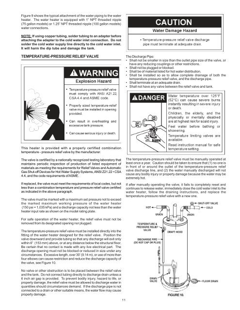
Figure 9 shows the typical attachment of the water piping to the waterheater. The water heater is equipped with 1” NPT threaded nipple(75 gallon models) or 1.25” NPT threaded nipple (100 gallon models)water connections.NOTE: If using copper tubing, solder tubing to an adapter beforeattaching the adapter to the cold water inlet connection. Do notsolder the cold water supply line directly to the cold water inlet.It will harm the dip tube and damage the tank.TEMPERATURE-PRESSURE RELIEF VALVEThe Discharge Pipe:• Shall not be smaller in size than the outlet pipe size of the valve, orhave any reducing couplings or other restrictions.• Shall not be plugged or blocked.• Shall be of material listed for hot water distribution.• Shall be installed so as to allow complete drainage of both thetemperature-pressure relief valve, and the discharge pipe.• Shall terminate at an adequate drain.• Shall not have any valve between the relief valve and tank.This heater is provided with a properly certified combinationtemperature - pressure relief valve by the manufacturer.The valve is certified by a nationally recognized testing laboratory thatmaintains periodic inspection of production of listed equipment ofmaterials as meeting the requirements for Relief Valves and AutomaticGas Shut-off Devices for Hot Water Supply Systems, ANSI Z21.22 • CSA4.4, and the code requirements of ASME.If replaced, the valve must meet the requirements of local codes, but notless than a combination temperature and pressure relief valve certifiedas indicated in the above paragraph.The valve must be marked with a maximum set pressure not to exceedthe marked maximum working pressure of the water heater(150 psi = 1,035 kPa) and a discharge capacity not less than the waterheater input rate as shown on the model rating plate.The temperature-pressure relief valve must be manually operated atleast once a year. Caution should be taken to ensure that (1) no one isin front of or around the outlet of the temperature-pressure reliefvalve discharge line, and (2) the water manually discharged will notcause any bodily injury or property damage because the water may beextremely hot.If after manually operating the valve, it fails to completely reset andcontinues to release water, immediately close the cold water inlet to thewater heater, follow the draining instructions, and replace thetemperature-pressure relief valve with a new one.For safe operation of the water heater, the relief valve must not beremoved from its designated opening nor plugged.The temperature-pressure relief valve must be installed directly into thefitting of the water heater designed for the relief valve. Position thevalve downward and provide tubing so that any discharge will exit onlywithin 6” (153 mm) above, or at any distance below the structural floor.Be certain that no contact is made with any live electrical part. Thedischarge opening must not be blocked or reduced in size under anycircumstances. Excessive length, over 30’ (9.14 m), or use of more thanfour elbows can cause restriction and reduce the discharge capacity ofthe valve, see Figure 10.No valve or other obstruction is to be placed between the relief valveand the tank. Do not connect tubing directly to discharge drain unless a6 inch air gap is provided. To prevent bodily injury, hazard to life, orproperty damage, the relief valve must be allowed to discharge water inquantities should circumstances demand. If the discharge pipe is notconnected to a drain or other suitable means, the water flow may causeproperty damage.11FIGURE 10.


