Minimum clearances between the water heater and combustibleconstruction are 0 inch at the sides and rear, 4” (102 mm) at the front,and 6” (153 mm) from the vent pipe. Clearance from the top of thejacket is 12” (305 mm) on most models. Note that a lesser dimensionmay be allowed on some models, refer to the label attached adjacent tothe gas control valve on the water heater, see Figure 3.INSULATION BLANKETSFIGURE 3.FIGURE 3.Insulation blankets are available to the general public for external useon gas water heaters but are not necessary with these products. Thepurpose of an insulation blanket is to reduce the standby heat lossencountered with storage tank heaters. Your water heater meets orexceeds the EPACT standards with respect to insulation and standbyloss requirements, making an insulation blanket unnecessary.Should you choose to apply an insulation blanket to this heater, youshould follow these instructions (For identification of componentsmentioned below, see Figure 1). Failure to follow these instructionscan restrict the air flow required for proper combustion, potentiallyresulting in fire, asphyxiation, serious personal injury or death.• Do not apply insulation to the top of the water heater, as this willinterfere with safe operation of the draft hood.• Do not cover the outer door, thermostat or temperature & pressurerelief valve.A gas water heater cannot operate properly without the correct amountof air for combustion. Do not install in a confined area such as a closet,unless you provide air as shown in the “Locating The New WaterHeater” section. Never obstruct the flow of ventilation air. If you haveany doubts or questions at all, call your gas supplier. Failure to providethe proper amount of combustion air can result in a fire or explosionand cause death, serious bodily injury, or property damage.• Do not allow insulation to come within 2" (50.8 mm) of the floor toprevent blockage of combustion air flow to the burner.• Do not cover the instruction manual. Keep it on the side of thewater heater or nearby for future reference.• Do obtain new warning and instruction labels from the manufacturerfor placement on the blanket directly over the existing labels.• Do inspect the insulation blanket frequently to make certain itdoes not sag, thereby obstructing combustion air flow.FIGURE 4.If this water heater will be used in beauty shops, barber shops, cleaningestablishments, or self-service laundries with dry cleaning equipment,it is imperative that the water heater or water heaters be installed sothat combustion and ventilation air be taken from outside these areas.Propellants of aerosol sprays and volatile compounds, (cleaners,chlorine based chemicals, refrigerants, etc.) in addition to being highlyflammable in many cases, will also change to corrosive hydrochloricacid when exposed to the combustion products of the water heater.The results can be hazardous, and also cause product failure.8COMBUSTION AIR AND VENTILATION FORAPPLIANCES LOCATED IN UNCONFINED SPACESUNCONFINED SPACE is space whose volume is not less than50 cubic feet per 1,000 Btu per hour (4.8 m 3 per kW) of the aggregateinput rating of all appliances installed in that space. Roomscommunicating directly with the space in which the appliances areinstalled, through openings not furnished with doors, are considered apart of the unconfined space.In unconfined spaces in buildings, infiltration may be adequate to provideair for combustion, ventilation and dilution of flue gases. However, inbuildings of tight construction (for example, weather stripping, heavilyinsulated, caulked, vapor barrier, etc.), additional air may need to beprovided using the methods described in “Combustion Air and Ventilationfor Appliances Located in Confined Spaces.”COMBUSTION AIR AND VENTILATION FORAPPLIANCES LOCATED IN CONFINED SPACESCONFINED SPACE is a space whose volume is less than 50 cubic feetper 1,000 Btu per hour (4.8 m 3 per kW) of the aggregate input rating ofall appliances installed in that space.
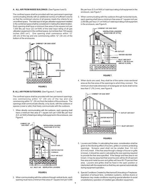
A. ALL AIR FROM INSIDE BUILDINGS: (See Figures 4 and 5)The confined space shall be provided with two permanent openingscommunicating directly with an additional room(s) of sufficient volumeso that the combined volume of all spaces meets the criteria for anunconfined space. The total input of all gas utilization equipment installedin the combined space shall be considered in making this determination.Each opening shall have a minimum free area of one square inch per1,000 Btu per hour (22 cm 2 /kW) of the total input rating of all gasutilization equipment in the confined space, but not less than 100 squareinches (645 cm 2 ). One opening shall commence within 12”(30 cm) of the top and one commencing within 12” (30 cm) of thebottom of the enclosures.Btu per hour (5.5 cm 2 /kW) of total input rating of all equipment in theenclosure, see Figure 7.3. When communicating with the outdoors through horizontal ducts,each opening shall have a minimum free area of 1 square inch per2,000 Btu per hour (11 cm 2 /kW)) of total input rating of all equipmentin the enclosure, see Figure 8.FIGURE 7.FIGURE 5.B. ALL AIR FROM OUTDOORS: (See Figures 6, 7 and 8)4. When ducts are used, they shall be of the same cross-sectionalarea as the free area of the openings to which they connect. Theminimum short side dimension of rectangular air ducts shall not beless than 3” (76.2 mm), see Figure 8.The confined space shall be provided with two permanent openings,one commencing within 12” (30 cm) of the top and onecommencing within 12” (30 cm) from the bottom of the enclosure. Theopenings shall communicate directly, or by ducts, with the outdoors orspaces (crawl or attic) that freely communicate with the outdoors.1. When directly communicating with the outdoors, each opening shallhave a minimum free area of 1 square inch per 4,000 Btu per hour(5.5 cm 2 /kW) of total input rating of all equipment in the enclosure, seeFigure 6.FIGURE 6.2. When communicating with the outdoors through vertical ducts, eachopening must have a minimum free area of 1 square inch per 4,0009FIGURE 8.5. Louvers and Grilles: In calculating free area, consideration shall begiven to the blocking effect of louvers, grilles or screens protectingopenings. Screens used shall not be smaller than 1/4 inch(6.4 mm) mesh. If the free area through a design of louver or grilleis known, it should be used in calculating the size opening requiredto provide the free area specified. If the design and free area is notknown, it may be assumed that wood louvers will be 20-25 percentfree area and metal louvers and grilles will have 60-75 percent freearea. Louvers and grilles shall be fixed in the open position orinterlocked with the equipment so that they are opened automaticallyduring equipment operation.6. Special Conditions Created by Mechanical Exhausting or Fireplaces:operation of exhaust fans, ventilation systems, clothes dryers orfireplaces may create conditions requiring special attention to avoidunsatisfactory operation of installed gas utilization equipment.