Technical Specification for A.C. Single Phase, 2 Wire ... - WBSEDCL
Technical Specification for A.C. Single Phase, 2 Wire ... - WBSEDCL
Technical Specification for A.C. Single Phase, 2 Wire ... - WBSEDCL

You also want an ePaper? Increase the reach of your titles
YUMPU automatically turns print PDFs into web optimized ePapers that Google loves.
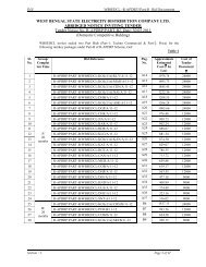
WEST BENGAL STATE ELECTRICITY DISTRIBUTION COMPANY LIMITED<strong>Technical</strong> <strong>Specification</strong>s <strong>for</strong> A.C. <strong>Single</strong> <strong>Phase</strong> , 2<strong>Wire</strong> Solid State( Static) Fully Electronic Energy Meter Accuracy Class: 1.0 , Current Rating(5-30) A, With Backlit LCD Display <strong>for</strong> 240 V SystemFitted inside Pilfer Proof Meter Box1.0 SCOPEa) This specification covers design, engineering, manufacture, testing, inspectionand supply of A.C. <strong>Single</strong> phase, two wire solid state (static) fully electronicenergy meters of accuracy class 1.0 and current rating (5-30) A, with backlitLCD display <strong>for</strong> 240 Volt systems as per requirement in this specification andpilfer proof meter box (PPMB) made of engineering plastic, FR grade with selfextinguishing property suitable <strong>for</strong> single phase meter. The meter should becapable of recording and displaying energy in KWH and demand in KW <strong>for</strong>single phase two wire A.C. loads respectively <strong>for</strong> power factor range of Zero lag– unity – Zero lead. Meters should have facility/ capability of recording tamperin<strong>for</strong>mation.b) It is not the intent to specify completely herein all the details of the design andconstruction of meter. However the meter shall con<strong>for</strong>m in all respects to highstandards of engineering, design and workmanship shall be capable ofper<strong>for</strong>ming commercial operation continuously in a manner acceptable to<strong>WBSEDCL</strong>, who will interpret the meanings of drawings and specification andshall have the right to reject any work or material which in its judgment is not inaccordance therewith. The offered meter shall be complete with allcomponents, accessories necessary <strong>for</strong> their effective and trouble freeoperation of the system <strong>for</strong> the purpose mentioned above. Such componentsshall be deemed to be within the scope of bidders supply irrespective ofwhether those are specifically brought out in this specification and / or thecommercial order or not.c) The original manufacturers of LT A.C. static energy meters shall only quoteagainst this tender. In case of <strong>for</strong>eign manufacturers their authorizedagent/agents may also participate provided that they are registered vendorsand have all the testing facilities in India. They should also produce thedocuments authorizing them as agents, in India.It is mandatory that in case of all manufacturers, the offered meter shallbe ISI marked and bidder shall have to furnish valid BIS certificationalong with the offer.
2.0 STANDARDS APPLICABLEUnless specified elsewhere in this specification, the per<strong>for</strong>mance & testing ofthe meters should con<strong>for</strong>m to the following Indian/International standards, to beread with up to date and latest amendments/revisions thereof as on 90 daysprior to floating of tender.Sl.Standard No.TitleNo.1 IS 13779, 1999 read with itslatest amendments<strong>Specification</strong> of AC Static Watt hour metersclass 1.0 and 2.02 CBIP Report No.304 readwith latest amendments<strong>Specification</strong> <strong>for</strong> AC Static Electrical EnergyMeters3 IS 12346 (1988) <strong>Specification</strong> <strong>for</strong> testing equipment <strong>for</strong> A.C.Static Electrical Energy Meter (latestamendment).4 C.E.A. Regulation No. 502 /70 / CEA / DP&D dt17/03/2006Central Electricity Authority (Installation andOperation of Meters) Regulation, 2006.5 IS 14434 (1998) Polycarbonate Molding and ExtrusionMaterials.3.0 CLIMATIC CONDITIONThe meters to be supplied against this specification should be suitable <strong>for</strong>satisfactory continuous operation under the following tropical conditions.Meters should be capable of maintaining required accuracy under hot, tropicaland dusty climatic conditions.i) Maximum Ambient Air Temperature in shade : 55 0 Cii) Minimum Ambient Air Temperature : (-)10 0 C.iii Maximum Relative Humidity : 95%(noncondensing)iv) Minimum Relative Humidity : 10%v) Height above mean sea level : Up to 3000 metersvi) Average number of tropical monsoon per annum : 5 monthsvii) Annual Rainfall : 100 mm to 1500mm4.0 SUPPLY SYSTEMSystemRated voltage (Vref)Rated CurrentRated Frequency1 <strong>Phase</strong> 2 <strong>Wire</strong>240 V – <strong>Phase</strong> to NeutralBasic current:- 5 Amps (lb),Maximum current:- 30 Amps (l max)50 Hz
5.0 POWER FACTOR RANGEThe meter should be suitable <strong>for</strong> full power factor range from zero (lagging)through to Unity to zero (leading).6.0 POWER SUPPLY VARIATIONThe meter should be suitable <strong>for</strong> working with following supply system variations.System1 <strong>Phase</strong> 2 <strong>Wire</strong>Specified range of operation 70% to 120% of reference Voltage i.e. 240 Volt.Frequency 50Hz +5%7.0 ACCURACY7.1 Class of accuracy of the meter should be 1.0. The accuracy should not drift withtime.7.2 Maximum error limit at 1% I b , UPF should preferably be within +/- 2%.7.3 For voltage variation use of “between 70% to 50%” of Vref.allowable error limit is+/- 4%.8.0 POWER CONSUMPTION8.1 Voltage Circuit:The active and apparent power consumption in the voltage circuit including thepower supply of meter at reference voltage, reference temperature and referencefrequency should not exceed 1.0 Watt and 4 VA respectively.8.2 Current Circuit:The apparent power taken by each current circuit at basic current, referencefrequency and reference temperature should not exceed 1 VA.9.0 STARTING CURRENT & RUNNING AT NO LOADThe meter should start registering energy at 0.2 % of basic current at unity powerfactor and first pulse must be appeared within 10 minutes (i.e. time between twoconsecutive pulses).Running at no load: When 70% and 120% voltage is applied and no current flowsin the current circuit, the test output of the meter should not produce more thanone pulse.10.0 MAXIMUM CONTINUOUS CURRENTThe maximum continuous current in meters should be the current at which themeter purports to meet the accuracy requirement of the specification. The same isindicated in table in clause 4 above.11.0 GENERAL & CONSTRUCTIONAL REQUIREMENTS
11.1 Meters should be designed and constructed in such a way so as to avoid causingany danger during use and under normal conditions. However, the followingshould be ensured.a) Personal safety against electric shockb) Personal safety against effects of excessive temperature.c) Protection against spread of fired) Protection against penetration of solid objects, dust & water11.2 The meter should be designed with ASIC (application specific integratedcircuit) and should be manufactured using SMT (Surface Mount Technology)components. Power supply and voltage divider circuits may be of PTH(Pin Through Hole) technology.11.3 The meter should be housed in a safe, high grade, unbreakable, fire resistant, UVstabilized, virgin Polycarbonate casing of projection mounting type. The metercover should be transparent, <strong>for</strong> easy reading of displayed parameters, andobservation of operation indicators. The meter base may not be transparent, but itshould not be black in colour. The meter casing should not change in shape,colour, size, and dimensions when subjected to 200 hrs on UV test as per ASTMD53. It should withstand 650 deg. C. glow wire test and heat deflection test as perISO 75.The meter cover should be sealable to the meter base with at least 2(two) nos.seals.11.4 The meter should be supplied with a transparent extended terminal block cover(ETBC). The ETBC should not be easily detachable from the base and be securedto the base using a hinge/ without hinge arrangement. ETBC should be closed atthe bottom to prevent access <strong>for</strong> wires to terminal holes, but should have a slot ofsize 20mm X 20 mm on extreme right hand side of the bottom of the terminalcover as per enclosed Drawing No.-(1). The terminal block should be made of highgrade non-hygroscopic, fire retardant, fire resistant and glass rein<strong>for</strong>ced polycarbonatewith terminal holes of minimum dia 5.5 mm and should be suitable toaccommodate the insulation of the conductors, meeting the requirement of IS13779 / CBIP technical report-304. The minimum center-to-center distancebetween adjacent terminals should be 13 mm.Terminal cover should have provision <strong>for</strong> sealing with at least one seal. Theembedded portion of the sealing arrangement, i.e. the arrangement to holdthe sealing screw <strong>for</strong> terminal cover should be such that the same cannot beuprooted in any case without breaking/damaging the terminal block.The bidder shall submit relevant documents regarding the procurement ofpolycarbonate material. The polycarbonate material of only the followingmanufacturers shall be used :a) G.E.Plastics/SABICLEXAN 943A or equivalent <strong>for</strong> cover & Terminalcover / LEXAN 503R or equivalent <strong>for</strong> base.b) BAYER Grade corresponding to abovec) DOW Chemicals - DO -d) MITSUBISHI - DO -e) TEJIN - DO -f) DUPONT - DO -
11.5 All insulating material used in the construction of meters should be nonhygroscopic,non-ageing and of tested quality. All parts that are likely to developcorrosion should be effectively protected against corrosion during operating life byproviding suitable protective coating.11.6 The meter should con<strong>for</strong>m to the degree of protection IP 51 <strong>for</strong> protectionagainst ingress of dust, moisture and vermin.11.7 The meter should be capable of providing phase to neutral protection up to433 V <strong>for</strong> 4 hours.11.8 The manner of fixing the cables to the terminal block should ensure adequate anddurable contact such that there is no risk of loosening or undue heating. Metershould have 2 (two) screws in each terminal <strong>for</strong> effective clamping of cables. Thescrews shall not have pointed ends at the end of the thread. Screw connectionstransmitting contact <strong>for</strong>ce and screw fixing which may be loosened and tightenedseveral times during the life of the meter should be such that the risk of corrosionresulting from contact with any other metal part is minimized. Electricalconnections should be so designed that contact pressure is not transmittedthrough insulating material. All terminals and connecting screws and washersshould preferably be of tinned / nickel plated brass material.The terminals and all connecting screws will be of suitable material capableof withstanding a current of 150% of Imax <strong>for</strong> two hours, continuously.11.9 The meter should be compact in design. The entire construction should becapable of withstanding stresses likely to occur in actual service and roughhandling during transportation. The meter should be convenient to transport andimmune to shock and vibration during transportation and handling.11.10 The meter should have fixing holes, at least one at top and two at bottom. The tophole should be such that the holding screw is not accessible after fixing themeters. The lower fixing screws should be provided under the sealable terminalcover.11.11 The meter should be fitted with SHUNT <strong>for</strong> measuring current in the phaseelement. The Neutral element may have either C.T. or SHUNT or HALL EFFECTSENSOR with proper isolation.The shunts, used in current circuit must be of high quality having high thermalstability and temperature co-efficient. The shunts should be E-Beam / Spotwelded.In case of Hall Effect Sensor, meter should record as per requirement oftechnical specification in normal and tamper conditions and life of battery used<strong>for</strong> recording and display during single wire operation as per clause 12 (IX) shouldbe guaranteed <strong>for</strong> 10 years.11.12 The meter cover should be permanently fixed to the meter base by using ultrasonic welding or any other technology which is either equally or more efficacious insuch a way that the meter cover can‟t be opened without breaking the same, i.e.the meter should be break-to-open type. In case any attempt is made to separatethe meter cover from the base by using any tools / implements / device, thereshould be visible evidence of tampering or attempt to open. The bidder will have tospecify the type of technology used by him and will also indicate the tests /standard required <strong>for</strong> testing the same along with test certificates. However,sealing with commonly available adhesives will not be accepted.
11.13 Meter should have a permanent indication in its display as well as logging oftamper in case of removal of top cover, even in power off condition and itshould not disappear even if cover is re-fitted.11.14 Sealing Arrangement: The sealing screws used <strong>for</strong> the meter cover shall be fixedupside down so that these are tightened from the rear or screw less design <strong>for</strong>fixing the base and cover but provision <strong>for</strong> sealing arrangement must be there. Arun through screw (stud) has to be provided from bottom side & sealing is to bedone on the top side of the meter. Two independent sealing screws are to beprovided at each sides of the meter casing. The sealing screws shall be TinnedBrass or Nickel Plated Steel/Brass. In addition to the sealing screws provided tothe meter cover, the sealing screws of the terminal cover should also be TinnedBrass or Nickel plated steel.Meters must be supplied with two no manufactures’ seal between meterbase and cover at both sides.12.0 ANTI-TAMPER FEATURESThe meter should have the following anti-tamper features and should record andregister <strong>for</strong>ward energy accurately under the following conditions :i) Input phase and neutral connections are interchanged. Reverse powerindication LED should be provided or indication should be in display circuit.ii) Incoming mains is connected to outgoing terminals and load is connectedto incoming terminals.iii) Any combination as permissible in all four connecting points should notaffect the accuracy of the meteriv) Load return is connected to a local earth and not returned to the meter aswell as the phase and neutral at supply side are reversed.v) Occurrence of combination of `(ii) and (iv)‟ or (iii)‟ and (iv)‟vi) A part of the load is returned to a local earth and the other part is returnedto the meter. “Earth load indication “should appear in display with logging oftamper, if difference between phase current and neutral current liesbetween 6% to 10%.
vii) Meter should record energy with maximum error of (+) 6% to (-) 4% onInjection of DC (+) ve & DC (-) ve in neutral having magnitude up to 400 V& injection of chopped AC in neutral. Tests in this respect will beconducted by using a device available with us <strong>for</strong> chopped AC injection(60V to 300V) & steady DC injection. DC voltage will be rectified from athree phase power supply. <strong>Single</strong> phase Circuit diagram of the deviceenclosed with the tender documents.viii) Meter should record energy with maximum error of +/- 4% even inabsence of neutral wire not connected at incoming & outgoing, i.e. singlewire operation. In such condition Meter should start recording energy at1.0 Amps. However, meters, which are immune or maintain betteraccuracy, will be preferred. Both elements should record energy undersingle wire mode if same phase is given in both elements and load isdriven through earth.ix) The meter should be immune to Electro Static Discharge or sparks of 35KVp. Approx generated from automobile ignition coil. Tests in this respectwill be conducted by using commonly available devices and during sparkdischarge test, spark will be applied directly at all vulnerable points of themeter <strong>for</strong> a period of 10 to 20 minutes and meter should record under thiscondition. After application of spark discharge meter should recordcorrectly within the specified limits of errors. Beyond 35 KVp meter shouldrecord as tamper if not immunex) In any case, meter should record energy accurately, taking the values of<strong>Phase</strong> current and Neutral current into account, whichever is higher..Meters should offer compliance to requirements of CBIP-304 and its amendments<strong>for</strong> tampering using external magnets. The meter should be immune to tamperusing external magnets. The meters should be immune to 0.2T of A.C. magneticfields and 0.27 T of D.C. magnetic fields, beyond which it should record as tamperif not immune. Meter should record Imax with the application of 0.5T permanentmagnet with logging in BCS, if not immune.
The meter should offer a link less design i.e. there is no isolation link providedbetween the current and voltage circuits and hence there would not be anypossibility of tampering with the same. The meter should be capable of recordingthe following tamper events in memory (minimum 25 events) with date and timestamp preferably along with snapshots of V, I, PF and Kwh. The logging will be onFIFO basis.- Current reversal- Neutral Disturbance- Magnetic Tamper13.0 DISPLAY13.1 The measured value(s) should be displayed on a Liquid Crystal display (LCD)register. The height X width of the digit should be minimum 8.0 X 5 mm. The KWhenergy registration should take place with 6 complete digits. The display shouldhave backlit capability <strong>for</strong> easy reading. When the LCD is placed at a constanttemperature of 65 deg C <strong>for</strong> a period of 30 minutes in operating condition and 80deg C <strong>for</strong> 30 mins. Under de-energized / storage condition, it should not getde<strong>for</strong>med.The LCD should be of TN (Twisted Pneumatic) type with display size area of atleast 40 X 15 mm. The display should have wide viewing angle of at least 70 deg.Dot Matrix type LCD will not be acceptable.Display should have viewing angle 35 degree up and down from eye level.13.2 The data should be stored in non-volatile memory (NVM). The non-volatilememory should retain data <strong>for</strong> a period of not less than 10 years under unpoweredcondition. Battery back-up memory will not be considered as NVM.13.3 The register should be able to record and display starting from zero, <strong>for</strong> aminimum of 2500 hours, the energy corresponding to rated maximum current atreference voltage and unity power factor. The register should not roll over inbetween this duration.13.4 In addition to provide serial number of the meter on the display plate, the meterserial number should also be programmed into meter memory <strong>for</strong> identificationthrough communication port <strong>for</strong> CMRI / Laptop / meter reading print out.13.5 It should be possible to read the meter during power off condition. It should also bepossible to read the meter with CMRI / Laptop in this condition. If battery is used<strong>for</strong> the same, it should be a separate battery and not the one used <strong>for</strong> RTC, i.e.,the RTC battery and the battery used <strong>for</strong> display during power off condition shouldnot be the same. The battery should be of high quality Lithium / Lithium – ionbattery, with life of at least 10 years. In case of Lithium battery, no. of operationsper day are to be restricted to maximum 5(five) operations so that battery life is nothampered during ten years.14.0 DISPLAY SEQUENCEThe meter should display the required parameters in two differentmodes as per the sequence given below.Display <strong>for</strong> Auto and manual mode must be listed by two headersA) Auto Display Mode andB) Push Button Modeand pasted in front of the PP Box
A) Auto Display Mode :The following parameters hereinafter referred to as “Billing Parameters” (B.P)should be displayed in an auto-cycle mode, in the following sequence :1. LCD Test2. Meter serial no3. Real Time4. Date5. Cumulative Active energy (<strong>for</strong>warded) reading (kWh)6. Cumulative Apparent energy reading (kVah)7. Last Bill Maximum demand (kW)/KVA8. Billing period counts9. Total tamper countEach parameter should be on meter display <strong>for</strong> 10 seconds and the time gapbetween two auto-cycles should be 120 secondsB) Push Button Mode :In addition to the auto display mode parameters, the following parameters shouldbe displayed on pressing the push button(All displays of auto mode and the following) :1. Last Bill Active Forward energy(kWh)2. Last Bill Apparent energy (kVAh)3. Instantaneous Load (KW)4. Instantaneous voltage,5. Instantaneous <strong>Phase</strong> current6. Instantaneous Neutral current7. Maximum demand kW and KVA <strong>for</strong> Current month8. Supply Frequency9. TOD Energy10. Instantaneous Power Factor11. High resolution displayThe meter should also be capable of offering a high resolution display whichshould enable conducting of dial testing by the user in the shortest possible timeand as a minimum, the meter should be capable of offering a resolution of 4 digitsafter decimal & 2 digits be<strong>for</strong>e decimal <strong>for</strong> the high resolution KWh display or 2digits after decimal and 4 digits be<strong>for</strong>e decimal <strong>for</strong> the high resolution Wh display.Any other useful display will be acceptable. Accuracy test <strong>for</strong> low load will bemeasured by short dial test as well as pulse count test.15.0 MAXIMUM DEMAND REGISTRATION AND RESETMeter should continuously monitor and calculate the average maximum demand<strong>for</strong> each demand interval time of 30 minutes and maximum of these in a calendarmonth should be stored along with date and time when it occurred. The maximumdemand should automatically reset at 24:00 hrs. of the last date of each calendarmonth and the corresponding value along with date/time stamp shall betransferred to Billing(History) registers.
The integration period should be set as 30 minutes, on real-time basis.The billing purpose parameters (active <strong>for</strong>warded energy, maximum demand inkW) should be recorded and should be available in Bill (History) <strong>for</strong> a minimumperiod of last 12 months.16.0 TIME OF USE / TIME OF DAY MONITORINGThe meter should offer the capability of time of use monitoring <strong>for</strong> energy.Minimum 2 registers should be capable of being configured <strong>for</strong> TOD monitoring <strong>for</strong>Peak / off peak hours. Time slots T1-23-00 Hrs. to 17-00 Hrs. of next day andT2-17-00 Hrs. to 23-00 Hrs. In case of any change of Time slots in future as perdirective of SERC, the same is to be incorporated by the supplier even aftercompletion of the order as per instruction from the appropriate authority.17.0 SELF- DIAGNOSTIC FEATUREThe meter should be capable of per<strong>for</strong>ming complete self diagnostic check tomonitor integrity of data memory location at all time. The meter should haveindication <strong>for</strong> unsatisfactory / nonfunctioning / malfunctioning of the following :a) Time and date on meter displayb) All display segments on meter displayc) Real Time Clock (RTC) status in meter reading prints out at BCS endd) Non-volatile Memory (NVM) status in meter reading prints out at BCS end18.0 COMMUNICATION PORTS AND PROTOCOL:The meter should have a galvanically isolated optical communication port <strong>for</strong> datacommunication with CMRI / Laptop. The port should be compatible with IEC1107/PACT/ANSI. Adequate sealing provision should be provided.19.0 CMRI / LAPTOP / BCS REQUIREMENTS:The Common Meter Reading Instrument (CMRI / Laptop) should be capable ofbeing loaded with user-friendly software (MS-DOS 5.0 or higher versioncompatible) <strong>for</strong> reading / downloading meter data. Windows based Base ComputerSoftware (BCS) should be provided <strong>for</strong> receiving data from CMRI / Laptop anddownloading instructions from base computer software to CMRI / Laptop..The BCS should be WIN Xp, WIN vista, WIN 7 pro based and copy righted.The data stored in the meters memory should be available on the BCS.
This BCS should have, amongst other requirements, features and facilitiesdescribed later in this specification, the facility to convert meter reading data intouser definable ASCII file <strong>for</strong>mat so that it may be possible <strong>for</strong> the user to integratethe same with the user‟s billing data and process the selected data in desiredmanner. All the data available in the meter including energy, MD, and history datashould be convertible to user defined ASCII file <strong>for</strong>mat <strong>for</strong> integration with thirdparty software. The vendor should supply necessary base computer software <strong>for</strong>reading / viewing of meter data and converting to user defined ASCII files <strong>for</strong>mats.The user should have the flexibility to select the parameters to be converted intoASCII file. The vendor should also supply the necessary CMRI / Laptop software.The bidder has to supply the Meter Reading protocol (API) free of cost. Theprotocol should not be complicated & should be easily understandable to introducecompatibility between meters, BCS and CMRI of other makes. The bidder shallindicate the relevant standard to which the protocol complies.The compatibility of transferring data from the meter to CMRI & then to the BCSshould be easily established. Any change or up gradation of CMRI software orBCS in future, required <strong>for</strong> any reason, has to be done by the supplier at his owncost.It should not be possible to change/alter date and time in the meter by sendingcommands from the CMRI or directly through Laptop. For alteration of RTC time,MD resetting, change of TOD timing, it should be possible to be done only throughauthenticated commands from BCS after scheduling of CMRI/Laptop <strong>for</strong> aparticular meter at the time of reading the meter. No alternation/change on theabove points should be possible through authenticated commands from BCSwithout scheduling of CMRI/Laptop <strong>for</strong> meters. Moreover, no alternation/changeshould be possible using CMRI only, i.e. the control has to be with the BCS.Billing parameters (KWH, KVAH, MD in KW & KVA, TOD wise KWH, Average P.F,and Average L.F).Only one BCS should be provided <strong>for</strong> programming and reading.100 nos. Meter to CMRI communication cord should be supplied to the office ofthe C.E. (DTD) <strong>for</strong> distributions at sites.20.0 DISPLAY POWER UP IN ABSENCE OF MAINS SUPPLYThe meter should have the provision of providing the display of billing parametersin absence of main supply. Press of push button should activate the display tofacilitate hands free meter reading with auto-off provision.It should be possible to read the meter using CMRI during power-off conditionusing this facility.21.0 MARKING OF THE METERThe marking on the meter should be in accordance with relevant clauses of IS13779.The basic marking on the meter nameplate should be as follows (all othermarkings as per IS should also be there) :
a) Manufacturer‟s name & trade markb) Type Designationc) No. of phases & wiresd) Serial number (Size not less than 5mm)e) Month & Year of manufacturef) Reference Voltageg) Rated Currenth) Operating Frequencyi) Principal unit(s) of measurementj) Meter Constant (imp/kwh)k) Class index of meterl) “Property of <strong>WBSEDCL</strong>”m) Purchase Order No. & Daten) Guarantee (Guaranteed <strong>for</strong> a period of 5 1 / 2 Yrs. from the date of delivery)o) BIS markingp) Place of manufactureq) Bar coded Sl no. of the meter along with manufacturing date.22.0 CONNECTION DIAGRAM & TERMINAL MARKINGS:The connection diagram of the meter should be clearly shown on terminalcover.23.0 OUTPUT DEVICEThe meter should have a test output accessible from the front and capable ofbeing monitored with suitable testing equipment while in operation at site. The testoutput device should be provided in the <strong>for</strong>m of LED output. There should beadequate clearance of the test output from other outputs so that there is nointerference of other outputs while per<strong>for</strong>ming accuracy test with standardscanners.The relation between test output and the indication on display should comply withthe marking on the name plate (imp per KWh)24.0 ELECTRO-MAGNETIC-COMPATIBILITY & INTERFERENCE REQUIREMENTThe meter should meet EMI / EMC requirements as specified in the relevantstandards described in Clause 2.0 of this specification.25.0 SEALING ARRANGEMENT :All meters shall be sealed by the manufacturer at its works with 2 (two) nos.Polycarbonate seals with manufacturer‟s logo and sequential numbers.A Tracking and recording software (25 nos. or more as per our requirement) <strong>for</strong> allnew seals shall be provided by the manufacturer of the meter so as to track totalmovements of the seals starting from manufacturing, procurement, storage, recordkeeping, installation, series of inspections, removal & disposal.Seal tracking software should be submitted and installed at PC/Laptop of thepurchaser be<strong>for</strong>e commencement of supply of meters.
General Requirements1. GUARANTEED TECHNICAL PARTICULARS :The bidder shall furnish all the necessary in<strong>for</strong>mation as desired in the Schedule ofGuaranteed <strong>Technical</strong> Particulars and data, appended with this <strong>Specification</strong>. If thebidder desire to furnish any other in<strong>for</strong>mation(s) in addition to the details as asked <strong>for</strong>,the same may be furnished against the last item of this Annexure–I2. TECHNICAL DEVIATIONS :Any deviation in <strong>Technical</strong> <strong>Specification</strong> as specified in the <strong>Specification</strong> shall bespecifically and clearly indicated in the Schedule of deviation <strong>for</strong>mat.3. TESTS :i) Type Testing of Meter:The offered meters should be type tested at any NABL accredited laboratory inaccordance with IS 13779 with latest amendments, CBIP Report 304 with latestamendments. The type test report should not be more than 3 (three) years old. Acopy of the Type Test results should be enclosed with the offer. If there is anymodification in the design/parameters of the specifications or use of constituentmaterials in the offered meters submitted with the offer, from the meter which wassubmitted type tested, which may affect the characteristics as well as parameters ofthe meter, revised type test certificates as per the design, parameters and constituentmaterial used in the offered meter, shall have to be submitted failing which the offermay be liable to be rejected.Type Test Certificate from any NABL accredited Lab. shall only be considered.Type test certificate should contain the following in<strong>for</strong>mation clearly :1) Class of accuracy.2) Meter constantii) Acceptance tests :A. The acceptance tests as stipulated in CBIP / IS (with latest amendments) and shallbe carried out by the supplier in presence of purchaser‟s representative. Lot size,sampling and procedure to be followed <strong>for</strong> acceptance test will be as stated belowThe lot size of Meters is 20,000 nos. & no. of Sample Meters to be selected atrandom from the lot is 32 nos.The following tests shall be carried out on all the 32 nos. meters thus selectedat random.The <strong>WBSEDCL</strong>‟s Engineers will witness the various quality control measuresadopted <strong>for</strong> verification of different components of meters and satisfythemselves about the same. They will also inspect the protocol <strong>for</strong> maintainingthe accuracy of the meter testing equipment with reference to the standard atmanufacturer‟s meters testing station.
Physical examination of the meters.Non-registration with Voltage along at 70% V ref and at 120% V ref.Starting current at 0.2% I basic UpfHigh voltage test.Insulation resistance test.Test of protection <strong>for</strong> withstanding 433 volt between phase & neutral <strong>for</strong> a period of atleast 4 hours without any load.Test of endurance up to 150% I maxDuring the above tests, if no of meter fails is less than or equal to 1 no., the lot shall beconsidered to be con<strong>for</strong>ming to the above tests. If no. of meter fails is greater than 1 no. butless than 4 (four), further re-sampling will be done and the numbers of re-sampled metersshall be 32, selected at random from the said Lot of 20,000 nos.The re-sampled meter will again be subjected to the tests as mentioned above and if numberof meters in two samples (combined) 64 (sixty four) nos. is less than 4 (four) nos., the lot shallbe considered to be con<strong>for</strong>ming to the above tests otherwise rejected.Further testing <strong>for</strong> 8 nos. meters selected from 32 nos. sample meters will be carriedas follows :Limits of error on all the sample meters at :1% I basic 1.0 pf. (±2% is preferable but should not exceed ±3%)2% I basic 1.0 pf.5% I basic 1.0 pf., 0.5 pf. Lag & 0.8 lead10% I basic 1.0 pf., 0.5 pf. Lag & 0.8 lead50% I basic 1.0 pf., 0.5 pf. Lag & 0.8 lead100% I basic 1.0 pf., 0.5 pf. Lag & 0.8 lead200% I basic 1.0 pf., 0.5 pf. Lag600% I basic 1.0 pf., 0.5 pf. LagTest of meter constant and meter dial <strong>for</strong> one unit at 200% I basic, 0.866 pf.Lag.Power loss on voltage & current circuit.Further testing <strong>for</strong> 3 Nos. sample meters will be carried as follows:Repeatability of error test at 5% I basic Upf & 100% I basic Upf.The maximum divergent should be less than 0.5%.If anyone of the meter fails on any of the above tests, the lot will be rejected.Further testing <strong>for</strong> 1 No. sample meter will be carried as follows:Magnetic induction of external origin (AC & DC).Electro Static Spark Discharge of 35KVpTamper and Fraud protection as per Clause 12 ( I to vii) (Anti-tamper feature)of our specification.Injection of DC pulse (low frequency) in the neutral.Dry –heat test as per clause 12.6.1 of IS: 13779/99.At least one sample selected from any lot of the meters offered <strong>for</strong> inspection will besealed by us and handed over to the supplier <strong>for</strong> testing at NABL accreditedlaboratory. Presence of purchaser‟s representative during dry heat test at NABLaccredited laboratory is not required. But in the test report meter Sl. No. & meterbody seal nos. is to be mentioned.
Shunt test by applying 100 Amps continuous load <strong>for</strong> minimum two hours afterremoving it from the meter <strong>for</strong> verification and con<strong>for</strong>mation <strong>for</strong> quality of shunt& its E-beam welding.Physical verification of internal components.If the meter fails on any of the above test, the lot will be rejected.Facilities/arrangement <strong>for</strong> conducting ageing test should be available with themanufacturer.iii)Retesting after delivery<strong>WBSEDCL</strong> will carry out re-testing of the supplied meters at their laboratory.Re-testing of the supplied meters will be conducted on sample meters collected fromdifferent stores of the consignees as per the procedure followed <strong>for</strong> acceptance test(except dry heat test & shunt test) during inspection & testing of the supplied metersat manufacturer‟s works. Re-testing of the supplied meters will be completed withinone month from the date of receipt of meters at different stores. Date of re-testing ofmeters will be intimated to the supplier <strong>for</strong> witnessing testing of the meters.In case the meters are not in order as per our observation during inspection andtesting of the supplied meters, the lot will be declared defective and in that eventmeters supplied are to be replaced by the manufacturers free of cost including freetransportation from the site to their works and back. The replaced meters are to beoffered <strong>for</strong> inspection & testing and Acceptance test of will have to be carried out bythe supplier in presence of purchaser‟s representative.iv) Routine Tests :Each and every meter of the offered lot shall undergo the routine tests as well asfunctional tests as per IS: 13779/1999, CBIP Report-304 and after sealing of themeters, the manufacturers will submit the routine test report of all the meters as wellas a statement showing seal Sl. Nos. against each meter, Sl. No. of offered lot in softcopy (MS WORD or EXCEL <strong>for</strong>mat), to the Chief Engineer, DTD, along with offerletter <strong>for</strong> acceptance test.v) TEST FACILITIES :The tests <strong>for</strong> equipment / instrument shall be carried out as per relevant Standardsand test certificates shall be furnished <strong>for</strong> scrutiny. The Bidder shall indicate thedetails of the equipment available with him <strong>for</strong> carrying out the various tests as perrelevant Standards. The bidder shall indicate the sources of all equipments/instruments.NOTE: The standard meters used <strong>for</strong> conducting tests shall be calibrated periodicallyat any NABL Accredited Test Laboratories and test certificates shall be available atWorks <strong>for</strong> verification by purchaser‟s representative.The manufacturer shall have the following testing facilities to ensure accuratecalibration :‣ AC high voltage test‣ Insulation test‣ Test of no load condition‣ Test of Starting condition‣ Test on Limits of error
‣ Power loss in voltage and current circuit‣ Test of Repeatability of error‣ Test of meter constant‣ Test of magnetic influence4. INSPECTION :The purchaser may carry out the inspection at any stage of manufacture. Themanufacturer shall grant free access to the purchaser‟s representative at areasonable time when the work is in progress. Inspection and acceptance of anyequipment under this specification by the purchaser shall not relieve the supplier ofhis obligation of furnishing the equipment in accordance with the specification andshall not prevent subsequent rejection if the equipment is found to be defective.All acceptance tests and inspection shall be made at the place of manufacturerunless otherwise especially agreed upon by the Bidder and purchaser at the time ofpurchase. The Bidder shall provide all reasonable facilities without charge to theinspector, to satisfy him that the equipment is being furnished in accordance with thisspecification.The supplier shall keep the purchaser in<strong>for</strong>med in advance, about the manufacturingprogramme <strong>for</strong> each lot so that arrangement can be made <strong>for</strong> inspection.The purchaser reserves the right to insist <strong>for</strong> witnessing the acceptance / routinetesting of the bought out items. The supplier shall give 15 days <strong>for</strong> local supply / 30days in case of <strong>for</strong>eign supply advance intimation to enable the purchaser to deputehis representative <strong>for</strong> witnessing the acceptance and routine tests.The purchaser reserves the right <strong>for</strong> type testing of any meter & meter casing etc.from any of the offered lots, received at any destination stores.5. SUBMISSION OF SAMPLE METER.The bidder will have to submit his/her sample Meters, PPMB and Seals in sealedcasing / carton along with relevant meter documents (as per Annexure-IV), on anyworking day, from 12.00 noon to 04.00 P.M. within the specified period of submissionof tender documents latest by 01.00 P.M. on the last day of submission of bid to theOffice of the Chief Engineer (DTD), Abhikshan, Sec-V, Salt Lake, Kolkata-91.A receipt, jointly signed by the representative of the bidder and DTD officials,mentioning the samples and papers submitted by the bidder as per check list willbe handed over to the representative.Tender paper will be accepted by the office of the „Chief Engineer (Procurement &Contract)‟, <strong>WBSEDCL</strong>, Bidyut Bhavan, 10th floor, Block – A & D, Salt Lake, Kol-91, on any working day ( excepting Saturdays) from 11.00 A.M. to 04.00 P.M. andlatest by 02.00 P.M. on the date of submission of tender. No tender will beaccepted without the receipt issued by DTD, Abhikshan in connection withsubmission of samples.
a) While submitting the samples and required documents as per Annexure-IV,the bidder has to submit two numbers of sealed meters as per thespecifications stated herein be<strong>for</strong>e, without the welding of the meter baseand cover and body screw caps.b) They should also submit one prototype of meter base and cover (with bodyscrew caps) properly welded, fitted inside a Pilfer Proof Meter Boxc) The tenderer shall have to submit 10 (ten) Nos. of each type of offeredseals.d) The tender without mentioned samples shall be rejected and notconsidered. The date of testing of sample meters will be intimated to thebidders by the C.E.(DTD) and on the date of testing of sample meters of aparticular bidder, the representative shall come prepared with thefollowings :‣ BCS (as per specification)‣ CMRI compatible with BCS and loaded with CMRI software andlaptop compatible with BCS.‣ Any other accessories required <strong>for</strong> observing the per<strong>for</strong>mance andcapabilities of the meters.‣ Operating/threshold value at which the meter will record energy asper specified limits of errors and also logic at which meter log tamperat different tamper conditions.Sample meter testing will be conducted as per the enclosed <strong>for</strong>mat (Annexure-V).During such testing, other bidders will also be allowed to witness the testing andonly one representative of each bidder with proper authorization letter from his/herorganization will be allowed to witness sample testing of a particular bidder.If any bidder send his/her representative to witness sample testing of otherbidders, the representative will have to be present till completion of sample testingof a particular bidder and test reports are to be signed by the representative.6. QUALITY ASSURANCE PLAN :The design life of the meter shall be minimum 20 years and to prove the design lifethe firm shall have at least the following quality Assurance Plan: -‣ The factory shall be completely dust proof.‣ The testing rooms shall be temperature and humidity controlled asper relevant standards.‣ The testing and calibrating equipments should be automatic and alltest equipment shall have their valid calibration certificates fromNABL accredited laboratory.‣ Power supplies used in testing equipment shall be distortion free withsinusoidal wave- <strong>for</strong>ms and maintaining constant voltage, currentand frequency as per the relevant standards.
During the manufacturing of the meters the following checks shall be carried out.i) Meter frame dimensions tolerances shall be minimum.ii) The assembly of parts shall be done with the help of jigs and fixtures so thathuman errors are eliminated.iii) The meters shall be batch tested on automatic, computerized test bench andthe results shall be printed directly without any human errors.The Bidder shall invariably furnish the following in<strong>for</strong>mation along with his bid,failing which his bid shall be liable <strong>for</strong> rejection. In<strong>for</strong>mation shall be separatelygiven <strong>for</strong> individual type of material offered.‣ Statement giving list of important raw materials, names of subsuppliers<strong>for</strong> the raw materials, list of standards according to which theraw materials are tested, list of tests normally carried out on rawmaterials.‣ In<strong>for</strong>mation and copies of test certificates in respect of bought outaccessories.‣ List of manufacturing facilities available.‣ Level of automation achieved and lists of areas where manual processingexists.‣ List of areas in manufacturing process, where stage inspections arenormally carried out of quality control and details of such tests andinspections.‣ List of testing equipment available with the bidder <strong>for</strong> final testing ofequipment specified and test-plant limitations, if any, vis-à-vis type, specialacceptance and routine tests specified in the relevant standards and thisspecification. These limitations shall be very clearly brought out in scheduleof deviations.The manufacturer laboratory must be well equipped <strong>for</strong> testing of the meters.They must have computerized standard power source and standard equipmentcalibrated not later than a year (or as per standard practice). The details of testingfacilities available <strong>for</strong> conductinga) The routine tests.b) Acceptance tests shall be furnished with the bid.7. MANUFACTURING ACTIVITIESAll the materials, electronics and power components, ICs used in the manufactureof the meter shall be of highest quality and reputed make to ensure higherreliability, longer life and sustained accuracy.The manufacturer should use Application Specific Integrated Circuit (ASIC) orMicro controller <strong>for</strong> metering functions.
The electronic components shall be mounted on the printed circuit board usinglatest Surface Mounted Technology (SMT) except power components bydeploying automatic SMT pick and place machine and re flow solder process. Theelectronic components used in the meter shall be of high quality and there shall beno drift in the accuracy of the meter at least up to 10 years. Further, the Biddershould own or have assured access (through hire, lease or sub-contract) of thementioned facilities. The PCB material should be of glass epoxy FR-4 gradecon<strong>for</strong>ming to relevant standards.All insulating materials used in the construction of meters shall be nonhygroscopic,non-aging and of tested quality. All parts that likely to developcorrosion shall be effectively protected against corrosion by providing suitableprotective coating.Quality should be ensured at the following stages:At PCB manufacturing stage, each board shall be subjected to bare board testing.At insertion stage, all components should undergo testing <strong>for</strong> con<strong>for</strong>ming to designparameters and orientation.Complete assembled and soldered PCB should undergo functional testing usingtest equipments (testing jig).Prior to final testing and calibration, all meters shall be subjected toaccelerated ageing test to eliminate infant mortality, i.e., meters are to bekept in ovens <strong>for</strong> 72 hours at 55 deg. Centigrade temperature & atmospherichumid condition. After 72 hours meters should work correctly. Facilities /arrangement <strong>for</strong> conducting ageing test should be available with themanufacturer.The calibration of meters shall be done in-house.The bidder should submit the list of components used in the meter along with theoffer.A detailed list of bought-out items, which are used in the manufacture of the meter,should be furnished indicating the name of firms from whom these items areprocured. The bidder shall also give the details of quality assurance proceduresfollowed by him in respect of the bought-out items.The details of testing facilities available <strong>for</strong> conducting the routine and acceptancetests and other special tests on the meter shall be furnished with the bid. Thefacility available if any <strong>for</strong> conducting type test may also be furnished.8. DOCUMENTATION :Operating manual should be provided inside each of the Pilfer Proof Meter Boxesand 20 no of additional quantity to be supplied to DTD store.One set of routine test certificates shall accompany each dispatchconsignment.The acceptance test certificates in case pre-dispatch inspection or a routine testcertificate in cases where inspection is waived has to be approved by thepurchaser.
9. GUARANTEE:The meters as well as the Pilfer Proof Meter Boxes should be guaranteed againstany manufacturing defects arising out of faulty design, material used, badworkmanship or component failure <strong>for</strong> a period of 5 ½ years from the date ofsupply.The guarantee of seals shall be as per guarantee of metersLife of battery used <strong>for</strong> the meter should be guaranteed <strong>for</strong> 10 (ten) years.The meter/battery found defective within the above guarantee period shall bereplaced by the supplier free of cost within 30 (thirty) days of the receipt ofintimation of failure / defect.REPLACEMENT OF DEFECTIVE METERS :The meters declared defective by the <strong>WBSEDCL</strong> shall be replaced by the supplierup to the full satisfaction of the <strong>WBSEDCL</strong> at the cost of supplier within 30 (thirty)days of receiving such intimation from the consignee stores or DTD and failure toreplace within the stipulated time limit shall lead to imposition of penalty of twicethe cost of meter. The same may even lead to black listing, as decided by<strong>WBSEDCL</strong>. In this connection the decision of <strong>WBSEDCL</strong> shall be final.10. PACKING & FORWARDING :The equipment shall be packed in cartons / crates suitable <strong>for</strong> vertical / horizontaltransport as the case may be, and suitable to withstand handling during transportand outdoor storage during transit. The supplier shall be responsible <strong>for</strong> anydamage to the equipment during transit, due to improper and inadequate packing.The easily damageable material shall be carefully packed and marked with theappropriate caution symbol. Wherever necessary, proper arrangement <strong>for</strong> lifting,such as lifting hooks etc., shall be provided. Supplier without any extra cost shallsupply any material found short inside the packing cases immediately.The packing shall be done as per the standard practice as mentioned in IS 15707:2006. Each package shall clearly indicate the marking details (<strong>for</strong> e.g.,manufacturer‟s name, Sl. Nos. of meters in the package, quantity of meter, andother details as per supply order). However, he should ensure the packing is suchthat, the material should not get damaged during transit by Rail / Road.11. GENERAL :a) Principle of operation of the meter, outlining the methods and stages ofcomputation of various parameters starting from input voltage and current signalsincluding the sampling rate, if applicable shall be furnished by the bidder.b) The Components used <strong>for</strong> manufacture of meter should be of high quality andthe bidders should confirm component specification as specified below inAnnexure-III.c) Bidders should compulsorily fill Annexure-I, Annexure-II & Annexure-III <strong>for</strong>technical qualification.
Component <strong>Specification</strong>s:The meters shall be designed and manufactured using SMT (Surface Mount Technology)components, except <strong>for</strong> power supply components, LED / LCD etc., which are PTH type.All the material and electronic power components used in the manufacture of the meter shallbe of highest quality and reputed makes so as to ensure higher reliability, longer life andsustained accuracy.Sl.no.ComponentFunction / FeatureRequirement1. Current Element E-beam /spot welded shunts shall beprovided in the phase element and C.T.in the neutral. Alternatively, both thecurrent elements (phase & neutral) shallhave Shunts with proper isolation.Make / originAny make or origincon<strong>for</strong>ming toIS-27052. Measurement /computing chipsThe Measurement / computing chipsused in the meter should be with theSurface mount type along with theASICs.Analog Devices, AMS,Cyrus Logic, Atmel,SAMES, NEC, TexasInstruments,Phillips,Teridian3. Memory chips The memory computing chips shouldnot be affected by the externalparameters like sparking, high voltagespikes or electrostatic discharges.4. Display modules The display modules should be wellprotected from the external UVradiations. The display should be clearlyvisible over an angle of at least a coneof 70 o .The construction of the modulesshould be such that the displayedquantity should not disturbed with thelife of display. The display should be TNtype industrial grade with extendedtemperature range.5. CommunicationmodulesCommunication modules should becompatible <strong>for</strong> the RS 232 ports6. Optical port Optical port should be used to transferthe meter data to meter readinginstrument. The mechanicalconstruction of the port should be suchto facilitate the data transfer easily.Atmel, NationalSemiconductors,Microchip, TexasInstruments, Phillips,Hitachi, Teridian ,STHaijing, Holtek,BonafiedTechnologies,Advantek, TrulySemiconductor,Hitachi, SONYNationalSemiconductors,Hitachi, TexasInstruments, Philips,HP, Agilent, Everlight,FairchildNationalSemiconductors,Hitachi, TexasInstruments, Siemens,Agilent, Philips,Hp,Everlight,Siemens
7. Power Supply The power supply should be with thecapabilities as per the relevantstandards. The power supply unit of themeter should not be affected in case themaximum voltage of the systemappears to the terminals due to faults ordue to wrong connections.As specified.8. ElectroniccomponentsThe active & passive componentsshould be of the surface mount type &are to be handled & soldered by thestate of art assembly processes.Philips, Toshiba,Fairchild, Murata,Rohm, Siemens.NationalSemiconductors,ATMEL, TexasInstruments, Hitachi.Ligitec, OKI, EPCOS9. Mechanical parts The internal electrical componentsshould be of electrolytic copper &should be protected from corrosion, rustetc.The other mechanical componentsshould be protected from rust, corrosionetc. by suitable plating / paintingmethods.10. Battery Lithium / Lithium-ion /Ni-Mh withguaranteed life of 10 years11. RTC / MicrocontrollerThe accuracy of RTC shall be as perrelevant IEC / IS standardsRenata, Panasonic,Varta, Tedrium,Sanyo, National,Teridian, Duracell,Maxell, ElegancePhilips, Dallas, Atmel,Motorola, NEC,Renesas, Hitachi,Xicor, TexasInstruments, NEC orOKI, ST,Mitsubishi
ANNEXURE - IGUARANTEED TECHNICAL PARTICULARS OF AC SINGLE PHASE, CL 1.0 (5-30A), STATICWHOLE CURRENT ENERGY METER WITH LCD DISPLAYSl.No.Particular1. Name of manufacturer2. Type, name & number3. Standard Applicable4. Type of Meter (Model No.)5. RatingMin. Requirement as per <strong>Specification</strong> of<strong>WBSEDCL</strong>IS:13779/1999, IS: 12346 / 1988, IS: 14434/ 1998, CEA regulation no. 502 / 70 / CEA /DT&D dt.17.03.06 and CBIP technicalreport no.304 with its latest amendment ason date..As offered(i) Accuracy Class Class-I(ii) Rated Voltage 240V (+ 20%, - 30%)(iii) Rated current Ib-5 Amp. Imax- 30 Amp(iv) Rated frequency 50 Hz ± 5%(v) Power factor Zero (lag) to Unity to Zero (lead)(vi) Minimum saturation current Bidders to specify(vii) Meter Constant (imp / KWH) -do-6. (i)(ii)Maxm. Continuous currentrating (Amp.)Continuous current rating ofterminals <strong>for</strong> two hours30 Amps.45 Amps(ii)7.8.9.Running with no load &(-)70% to 120 % voltageShort time over current <strong>for</strong> 10millisecondsStarting current at which metershall run & continue to runPower loss at rated frequency& reference temperatureNo creeping30 Imax <strong>for</strong> one half cycle at ratedfrequency0.2% of Ib at rated voltage and unity powerfactor(a) Current circuit at rated current Less than 1 VA(b) Voltage circuit at rated current Less than 1.0W / 4VA10. Type of material used(a) Base
Sl.No.ParticularMin. Requirement as per <strong>Specification</strong> of<strong>WBSEDCL</strong>As offeredMaterialHigh Impact strength, non-hygroscopic, fireretardant, fire resistant, UV stabilised polycarbonate (Lexan 503R or equivalent)(b)(c)(d)(f)11.12.Meter coverTerminal BlockMaterialTerminal coverMaterialScrew(i) Material(ii) SizeInternal diameter of TerminalHoleCentre to Centre clearancesbetween adjacent terminalsHigh Impact strength, non-hygroscopic, fireretardant, fire resistant, UV stabilisedTransparent poly carbonate (Lexan 943A orequivalent)Material High Impact strength nonhygroscopic,fire retardant, fire resistant,UV stabilised poly carbonate (Lexan 500Ror equivalent)Barrier of adequate size shall be providedbetween phase and neutralHigh Impact strength, non-hygroscopic, fireretardant, fire resistant, glass rein<strong>for</strong>cedpoly carbonate (Transparent)& nondetachable with hinging arrangement(Lexan 943A or equivalent).Tin / Nickel Plated - BrassBidders to specifyMin. 5.5 mm13 mm13 Transducers(i)Input(ii) Output LCD(iii) Shunt resistivity Bidders to specify(iv) C.T. – no of turns -do-E-beam / spot welded Shunts shall beprovided in the phase element and C.T/Shunt/ HALL EFFECT SENSOR in theneutral.Voltage: Potential divider (PT less). Type of Register LCD suitable <strong>for</strong> operation up to 80 o C(i) No. of Digits 6 (integer only)(ii) Size of Numerals 8.0 X 5 mm (minimum)15. Display(i)On Scroll Mode & Auto displaymodeBoth required as per sequence mentionedin <strong>Technical</strong> <strong>Specification</strong> clause No.14
Sl.No.ParticularMin. Requirement as per <strong>Specification</strong> of<strong>WBSEDCL</strong>As offered(ii)Type of push buttonSpring loaded/ Rubber elastomer pushbutton to be provided on top cover of meterto read parameters16.Reading on power offconditionMeter shall be able to display readingduring power outage through the pushbutton provided on the meter with facility <strong>for</strong>hands free meter reading with auto-offprovisions.17. a) Battery of Real time clock(i) It shall be Lithium/Lithium-ion batteryhaving at least 10 years of life(ii) The drift in time shall not exceed +/- 3minutes per yearb) Battery <strong>for</strong> Display duringpower off conditionIt shall be Lithium / Lithium-ion/ NiMhbattery having at least 10 years of life18. Fixing/sealing arrangement(i) Fixing of meter(ii) Sealing of meter cover toBase3 fixing holes (one at top & two at bottomunder terminal block). The top fixing screwshall not be accessible after meter is fixedto meter box base.At least, two sealing provision/screws shallbe provided <strong>for</strong> proper fixing of the metercover so that access to the working partshall not be possible without breaking theseal. Necessary provision shall be kept <strong>for</strong>fixing the utility seal also.19.20.Type of hinged un-detachableterminal coverPer<strong>for</strong>mance of meter intamper conditions(i) <strong>Phase</strong>-neutral interchanged(ii) Main & load wire areinterchanged(iii) Load is not terminatedback to meter & current isdrawn through local earth fullyor partiallyThe meter cover shall be permanently fixedto the base by ultrasonic welding or anyother technology which is equally or moreefficacious so that cover cannot be openedwithout breaking, i.e. the meter should bebreak to open type.Meter should have an indication in itsdisplay if top cover is removed.Terminal cover shall be either hinged/ nonhingedShould work within specified accuracy----do-------do----
Sl.No.Particular(iv) Neutral disconnected fromboth incoming & outgoing andload drawn through local earthMin. Requirement as per <strong>Specification</strong> of<strong>WBSEDCL</strong>-do- provided threshold current is 1 Amp. &aboveAs offered(v) Indication of above tamperconditionLCD / LED indication.21.Suitability of meter to sustainover voltage i.e. phase tophase voltage injectedbetween phased & neutralShould sustain22Electromagnetic compatibility(EMI / EMC severity level)As per IS 13779: 199923.(i) Effect on accuracy ofexternal electromagneticinterference of electricaldischarge, external magneticfield & DC current in ACsupply or in neutralShould work within accuracy as per latestIS & CBIP report -304 with latestamendment.(ii) Immune to Electrostaticdischarge upto 35kVpExceeding 35kVp it should log as tamper(iii) Current reversal, Neutraldisturbance & Magnetictamper logging in memoryMeter shall log last 25 events with date andtime24.Effect on accuracy undertamper conditions / influenceconditionsShould work within accuracy specified inIS: 13779 / 1999, and CBIP tech. Report304 . Error beyond +/- 4 % will not beacceptable <strong>for</strong> conditions not specified inIS: 13779 / 1999 & CBIP tech. Report 30425.Drift in accuracy ofmeasurement with timeNo Drift in accuracy in measurement withtime26. Name plate details27. Approximate weight of meter To be indicated28. Type of mounting Projection typeIt should cover all the details as prescribedin Clause-2129. CalibrationMeter shall be software calibrated at factory& there shall not be any mechanical <strong>for</strong>m ofcalibration, such as, mechanical preset /trim port / potentio etc. so that anyadjustment in calibration is not possibleafter freezing the meter constant.30. Manufacturing activity(i) Mounting of components onPCB shall be SMT typeSMT type and ASIC technology
Sl.No.Particular(ii) Compliance to assurance31. Testing facility(i)Fully automatic computerisedmeter test bench with print outfacility shall be availableMin. Requirement as per <strong>Specification</strong> of<strong>WBSEDCL</strong>To be compliedMust be availableAs offered(ii)(iii)Make and Sl. No. of TestbenchAccuracy of ESS dulycalibratedTo be indicated---do---(v)Following in house testingfacility shall be available :(i) AC high voltage test(ii) Insulation test(iii) Test of no load condition(iv) Test of Starting condition(v) Test on Limits of error(vi) Power loss in voltage andcurrent circuit(vii) Test of Repeatability oferror(viii) Test of meter constant(xi) Power loss in voltage ¤t circuitMust be available--do----do----do----do----do----do----do----do--(x) Test of Magnetic influence --do--32.Whether offered meter typetested as per ISS 13779 /1999 Table-20 <strong>for</strong> all thefollowing tests (indicate nameof laboratory /Reference ofreport No. & date)Clause No – 3 of general requirement.(i) Vibration test 12.3.2(ii) Shock test 12.3.1(iii) Spring Hammer test 12.3.3Protection against penetration(iv)12.5of dust and water(v) Test of resistance to heat & 12.4fire(vi) Power consumption 12.7.1(vii) Influence of supply voltage 12.7.2(viii) Voltage dips and interruptions 12.7.2.1.(ix) Short time over current 12.7.3(x) Influence of self heating 12.7.4(xi) Influence of heating 12.7.5(xii) Impulse voltage test 12.7.6.2(xiii) AC high voltage test 12.7.6.3Name ofLab Typetest ReportRef. No.
Sl.Min. Requirement as per <strong>Specification</strong> ofParticularNo.<strong>WBSEDCL</strong>(xiv) Insulation test 12.7.6.4.(xv) Radio Interference12.9.5measurements(xvi) Fast transient burst test 12.9.4(xvii) Electrostatic discharge 12.9.2As offered(xviii)Immunity to electro-magneticH.F. field12.9.3.(xix) Test <strong>for</strong> meter constant 12.15(xx) Test of starting conditions 12.14(xxi) Test of no load condition 12.13(xxii) Ambient temp. influence 12.12(xxiii) Test of influence quantities 12.11(xxiv) Interpretation of test results 12.16(xxv) Repeatability error test 12.17(xxvi) Dry heat test 12.6.1(xxvii) Cold test 12.6.2(xxviii) Damp heat cycle test 12.6.3(xxix)Test of influence of immunityto Earth fault12.8(xxx) Limits of error 11.133. Guarantee period of meter34. BIS licence34.134.2(i)(ii)(iii)BIS licence No. & dt. with itsvalidity <strong>for</strong> ISI certificationmark on offered meter.Details of meter design <strong>for</strong>which above BIS certificationhas been obtained: -Ratio of Ib to ImaxMaterial of meter bodyType of energy registeringcounter5-1/2 years from the date of supply.Guarantee period shall be printed on thenameplate.To be mentionedTo be mentioned(iv)(v)(vi)`(vii)(viii)Type of technology(Digital/Analog)Grade of printed circuit BoardmaterialType of assembly ofcomponent used (SMT)Meter constant (IMP / KWh)Auxiliary power circuit (with PTor PT less)
Sl.No.ParticularMin. Requirement as per <strong>Specification</strong> of<strong>WBSEDCL</strong>As offered(ix)Current circuit (CT / Shuntcombination or only shunt)(x)Accuracy class35.ISO accreditation no. & dt. withits validity36.Other parameters / featuresnot covered in the above GTPCon<strong>for</strong>m to specification of IS-13779 / 1999and CBIP technical report No.304 (with itslatest amendment).37 Past ExperienceCopies of order executed in last two yearsalong with GTP of the supplied meters to beenclosedAnnexure - IIPre-Qualification Conditions <strong>for</strong> <strong>Single</strong> <strong>Phase</strong> Static MetersSl. No. Particulars Remarks1Bidders must have valid BIS certification <strong>for</strong> theoffered meter.Yes / No2 Bidder preferably posses ISO 9001 certification Yes / No3456Bidder should be manufacturers of static metershaving supplied Static 1-ph or 3-phase meters withmemory and LCD display to Electricity Boards /Utilities in the past 3 yearsBidder has Type Test certificate <strong>for</strong> the Type ofoffered meter not more than 3 (three) years oldBidders should have dust free, static protectedenvironment <strong>for</strong> manufacture, assembly andTesting.Bidder should have automatic computerized testbench <strong>for</strong> lot testing of meters.Yes / NoYes / NoYes / NoYes / No7 Bidder has facilities of Oven <strong>for</strong> ageing test. Yes / No8Bidder shall submit certificate <strong>for</strong> immunity againstmagnetic influence of 0.2 T AC. & 0.5 T DC. froma NABL accredited Laboratory, <strong>for</strong> the same typeof meter as offered.Yes / No
Annexure - IIISl.No.ComponentFunction /FeatureAs per RequirementMake / origin1 Current Element2Measurement /Computing chips3 Memory chips4 Display modules5Communicationmodules6 Optical port7 Power Supply8Electroniccomponents9 Mechanical parts10Battery11RTC / Microcontroller
ANNEXURE - IVSl.No.1LIST OF DOCUMENTS TO BE SUBMITTEDDURING SAMPLE SUBMISSIONAttested copy of type test reports from NABLaccredited laboratory23Attested copy of BIS certificates of the sametype of meter submitted as sampleAttested certificates as regards material used <strong>for</strong>meter case, cover & terminal block.4 Annexure – II as per tender documents5 Annexure – III as per tender documents6 Operating manual of the meter submitted
Reference:Date of Test :-Name of bidder /Manufacturer:Address:-ANNEXURE - IVADescription of Meter :-Test Per<strong>for</strong>med:-Serial NoTypeVoltageCurrentImpulse/KwhClassMfg. Dt.Sl. No. Description of Test1.) Meter subjected to 450V between <strong>Phase</strong> and Neutral <strong>for</strong> 4 hours:Result:-Meter terminals subjected to 150% Imax <strong>for</strong> 2 hours.Result:-2.)InsulationResistance Result:- Measured Points Limit ( Min. )Between Frame & <strong>Phase</strong>CircuitBetween Frame &Neutral CircuitObs.Values3.) Power Loss:MeasuredPointsVoltageCircuitCurrentCircuitLimitWattVAVA1.04.01.0Obs.Values4.) No Load Limit Obs. Values120% of RatedMax. 1VoltageResult:- pulse70% of RatedvoltageResult:-Max. 1pulse5.) Starting Current0.2% of Ib Result:- Limit Observation< 10minutes.
6.) Description of Test:Limits of Error Load P.F.Errors asperIS13779 /CBIP304Imax 1.0 (±) 1%0.5 lag (±) 1%0.8 ld (±) 1%%Error <strong>for</strong>Active <strong>Phase</strong>% ErrorForActiveNeutral200% Ib 1.0 (±) 1%0.5 lag (±) 1%Ib 1.0 (±) 1%0.5 lag (±) 1%0.8 ld (±) 1%50% Ib 1.0 (±) 1%0.5 lag (±) 1%0.8 ld (±) 1%10%Ib 1.0 (±) 1%0.5 lag (±) 1.2%0.8 ld (±) 1.2%5%Ib 1.0 (±) 1%0.5 lag (±) 2%0.8 ld (±) 2%2%Ib 1.0 (±) 2%1%Ib 1.0 (±) 2%7.)Repeatability ofError 1 2 3 4 5 6 DiffLoad 5% Ib UPFLoad 100% Ib UPF1 2 3 4 5 6 DiffReproducibility ofError 1 2 3 4 5 6 DiffLoad 5% Ib UPFLoad 100% Ib UPF1 2 3 4 5 6 Diff
8.) Voltage VariationLoad P.F. Voltage Obs Error(%) Active200%Ib 1.0 0.7 Vref.200%Ib 1.0 1.2 Vref.9.) Dial test200% Ib 0.866 lag200% Ib 0.866 lagActiveEnergyM.D.(Active)Duration :30 MinutesMeter Under testSub-Standard Meter X MF% Error observedMeter Under testSub-Standard Meter X MF% Error observedAdvancement10.)<strong>Single</strong> <strong>Wire</strong>OperationLoadPF1.0 Amps 1.0Limit(%)(+/-)4.0Observed %Error(Active)11.) Tampers Features checkedInput phase & Neutral are reversed (Recording in <strong>for</strong>warddirection)Source side & Load side are interchange (Recording in<strong>for</strong>ward direction)Combination of above two<strong>Single</strong> wire OperationPartial Earth Load( 50% load currentgoes to earth)Potential ReduceNeutral Disturbance by D.C injectionNeutral Disturbance by chopped ACinjectionMagnetic TamperSpark DischargeObservation12.)BCS &Communication
13.) Meter Display14.)PhysicalExamination15.) General RemarksSignature ofManufacturer Witness Representative of <strong>WBSEDCL</strong>Representative.
1.0 SCOPE:TECHNICAL SPECIFICATION FOR PILFER PROOF METER BOXSUITABLE FOR SINGLE PHASE STATIC ENERGY METER1.1 This specification covers manufacture and supply of Pilfer Proof Meter Box (PPMB) suitableto house <strong>Single</strong> <strong>Phase</strong> Static Energy Meter. The Meter Box shall be wall mounted type.ability so as to offer protection of electrical equipment against harsh weather. The box shallbe anti-corrosive, dust proof, shock, vermin & waterproof, pilfer proof, fire proof and UVstabilized. The enclosures shall not de<strong>for</strong>m or melt when exposed to fire.2.0 TECHNICAL REQUIREMENT :2.1 The Meter Box i.e base and cover shall be made of hot press/injection moulded,unbreakable, high grade fire retardant Engineering Plastic (Acrylonitrile ButadieneStyrene)/Polycarbonate, with minimum thickness 2.0 mm having good di-electric andmechanical strength. The material must be such that the Meter Box should not change incolor, shape. Size, dimensions when subjected to Ageing Test. The Meter Box should havetop tapered surface and round corners to prevent any water logging on the top of metercover. The overall dimensions of the enclosure shall be suitable <strong>for</strong> housing single phasemeter as offered by the bidder and there should be a clearance of 30 + 2 mm from top &both sides of the meter. Bottom side clearance should be 75 + 5 mm from the lower edgeof terminal block of the meter. Clearance from front side and back side of the meter shouldbe 15 + 2 mm and 10 + 2 mm respectively. Meter Box with higher dimensions may beconsidered if found suitable.2.2 The Meter Box should be capable of withstanding the mechanical, electrical and thermalstresses well as the effects of humidity which are likely to be encountered in service. At thesame time the box should ensure desired degree of safety. The material used should beadequately stabilized against detrimental effect of light and weather. The surfaceappearance of the moulded parts must be smooth, non-porous and homogeneous, free ofripples, defects and marks. No fillers of fibers should be visible at any place.2.3 The box should comply in all respect with the requirement of latest amendments ofIS /ASTM. Applicable degree of protection shall be IP 42 or better.2.4 All accessories like nuts, bolts, washers etc. shall be galvanized.3.0 CONSTRUCTION :3.1 The enclosure shall be single piece moulded with hot process compression molding orinjection molding.3.2 Dimension: To be specified by the bidder.3.2 Hinges :A minimum of 2 nos. brass/stainless steel hinges in left side of the door and 1 no.brass/stainless steel hinge/stainless steel U type latch with locking arrangement in rightside of the door shall be provided inside the enclosure. The hinges of the door shall beconcealed and they shall be fixed to the flanges provided on the body and cover of theenclosure in such a manner that the door opens by a minimum of 120 degrees.3.3 Suitable grove with locking arrangement shall be provided <strong>for</strong> opening of the enclosuredoor.3.4 Earthing Bolt :8mm dia. G.I. bolt with 2 nos. washers <strong>for</strong> earthing all metal parts shall be provided.
3.5 Fixing arrangement :The meter box shall have 4 nos. of mounting brackets made out of same material as meterbox with provision <strong>for</strong> 6 mm dia hole <strong>for</strong> mounting the box on the wall or wooden boardwith suitable screws. The meter box shall have provision to fix it on the wall or woodenboard with the meter in assembled condition. Four (4) nos. self threaded screws ofminimum size of 4 mm dia and 25 mm long shall be provided with each meter box.Any other suitable arrangement <strong>for</strong> fixing the box may be accepted after verification.3.6 Sealing arrangement :The Box should have provision <strong>for</strong> padlocking and also <strong>for</strong> sealing arrangement of the basewith cover providing holes <strong>for</strong> 1 no. seal to make it fully tamper proof.3.7 Incoming and outgoing cable arrangement :Suitable 2 (two) Nos. of holes at bottom (12 mm. dia) shall be provided in the box <strong>for</strong>cable/wire entry. 2 (two) holes must be totally covered with neoprene rubber gasket (NRG).NRG will be punched <strong>for</strong> entry of incoming and outgoing cable/wire.3.8 Base and Cover details :Thickness of the meter box shall not be less than 2.0 mm on all sides including door. Themeter box shall have 4 mm thickness of the tongue and groove area. The meter box covershall be made overlapping type having collars on all four (4) sides and shall be providedwith Neoprene rubber gasket of minimum 2.5 mm dia to completely fit in the grooves of thebase. The base of the meter box must have a groove to hold the gasket and the overlap ofthe top cover with base should be sufficient. The tongue of the base shall ensure propersealing arrangement against ingress of rainwater and dust inside the box.3.9 The Enclosures shall generally comply with the provision of IS 14772 or IEC 695. Theenclosures shall be suitable <strong>for</strong> outdoor application. The enclosure shall be with goodworkmanship.3.10 Soft neoprene/nitride rubber gaskets shall be provided all round wherever required <strong>for</strong>protection against entry of dust and water. The gasket shall confirm to Type-III as per IS-11149. The enclosure shall comply with IP-42 or better degree of protection.3.11 The Enclosures shall be off white/admiral gray / ivory/ transparent polycarbonate.3.12 Marking/Embossing:The following in<strong>for</strong>mation shall be clearly & indelibly embossed/laser printed on the coverand base of the Meter Box. The top & bottom corner of Meter Box Sl. No. shall be same <strong>for</strong>the particular Meter Box.i) Property of <strong>WBSEDCL</strong>ii) Name/Brand name of Manufactureriii) Meter Box Sl. No. (Embossed / laser printing on both the base and covers ofMeter Box)iv) Sign of Danger4.0 Submission of Sample :4.1 The bidder shall submit a sample Meter Box as per our specification along with the samplemeter to the office of the Chief Engineer, (DTD), Abhikshan Bhavan, Sector-V, Salt Lake,Kolkata-91 be<strong>for</strong>e the last day of submission of bid.4.2 Submission of sample meter box as per size available with the bidder but con<strong>for</strong>ming to ourspecification towards its quality is acceptable . Type testing including material identification(IR Spectrometry test) of one meter box manufactured as per specification is to beconducted at any NABL accredited laboratory/CIPET by the supplier at their own cost afterplacement of order. For type testing the meter box will be selected from the first offered lotof meter with meter box. If the type test results are not found satisfactory, the offered lotof meter along with meter box will be rejected.
5.0 Quality Control:5.1 Type test reports from CIPET/NABL accredited laboratory as per Standard IS/ASTM shall besubmitted. The type test reports shall not be more than 5 (five) years old. Acceptance testsas per IS/ASTM are to be carried out by the supplier in presence of <strong>WBSEDCL</strong>’srepresentative. Material of meter enclosure shall be tested <strong>for</strong> Heat Deflection Temperature,Exposure to Flame (Self-extinguishing) and Resistance to Heat & Fire (Glow wire) as perspecification and Ref. Standard IS/ASTM.6.0 General Construction Requirement:6.1 Viewing Window:A viewing window as per drawing made up of scratch and break resistant, UV resistant,transparent Polycarbonate material shall be provided on the door <strong>for</strong> reading the meterwithout inconvenience. The minimum thickness of the viewing window shall be 2.0mm.(flashing with top). The viewing window shall be provided with fixed rain hood. Thewindow shall be securely fixed with meter enclosure from inside. Suitable neoprene gasketshall be provided so that there shall not be any ingress of moisture through this windowinto the enclosure.No viewing window is required <strong>for</strong> transparent polycarbonate meter box.6.2 Construction of louver:Louver must be provided in one side of the pilfer proof box inside of which must be coveredwith the mesh (plastic) in such a way that from outside that mesh can not be approached.No louver is required <strong>for</strong> transparent polycarbonate meter box.6.36.3 One push button is to be provided on the front side of the top cover of meter box <strong>for</strong> takingmeter reading during power off condition without opening of meter box cover.7.0 Guarantee:The Pilfer Proof Meter Box should be guaranteed against any manufacturing defects arisingout of faulty design or bad workmanship or component failure <strong>for</strong> a period of 5 ½ yearsfrom the date of supply.The meter box found defective within the above guarantee period shall be replaced by thesupplier free of cost within one month of the receipt of intimation of failure/defect.Defective meter box are to be replaced by new one with new sl. nos. as allotted byC.E (DTD).8.0 Replacement of defective Meter Box :The Meter Box declared defective by the <strong>WBSEDCL</strong> shall be replaced by the supplier up tothe full satisfaction of the <strong>WBSEDCL</strong> at the cost of supplier. Failure to do so within the timelimit prescribed shall lead to imposition of penalty of twice the cost of meter box. The samemay lead to black listing even, as decided by <strong>WBSEDCL</strong>. In this connection the decision of<strong>WBSEDCL</strong> shall be final.9.0 Testing:a) Type Test:The bidder must furnish type test report including material verification of the offered/sample meterbox from any NABL/Govt. approved laboratory as available with them along with technical bidwithout which the offer will not be considered. Type test report should not be more than 5(five) years old.Type testing at any recognized NABL accredited laboratory/CIPET in respect of one meter box as perthe specified size, selected from any one of the offered lot during supply is to be conducted by thesupplier at their own cost after placement of order <strong>for</strong> verification of material and quality of the box.
If the type test results are not found satisfactory, the offered lot of meter along with the meter boxwill be rejected.b) Acceptance Test:The acceptance test as stipulated in Annexure-VI shall be carried out at the time of inspection of theoffered material.c) Routine Test:The routine tests as stipulated in the Annexure-VI shall be carried out and routine testcertificate/reports shall be submitted to Chief Engineer (DTD), <strong>WBSEDCL</strong>, Abhikshan, Sector-V, SaltLake City, Kolkata-700091 while offering inspection & testing of the meter with meter box.Notes:1) Where facilities do not exist at supplier’s works <strong>for</strong> carrying out one or more ofthe Acceptance Tests as per Annexure-VI, such tests may be carried out at anyof the approved laboratories such as CIPET/IIT/National Test House/Govt.approved laboratory etc. in presence of <strong>WBSEDCL</strong>’s representative.2) The sampling plan <strong>for</strong> carrying out the acceptance tests shall be as per IS.9.0 Submission of Drawing:Three (3) copies of drawing complete in all respect should be submitted to the C.E (DTD)under intimation to the Material Controller <strong>for</strong> accordance of approval immediately afterplacement of order. 25 copies of approved drawing are to be submitted <strong>for</strong> distribution tosites.10.0 Inspection:The inspection will be carried out as per inspection & testing clause of General Conditions ofContract (GCC).11.0 Guaranteed <strong>Technical</strong> Particulars:The bidder shall furnish all the necessary in<strong>for</strong>mation as per Annexure-VII - Guaranteed<strong>Technical</strong> Particulars. If the bidder desire to furnish any other in<strong>for</strong>mation in addition to thedetails as asked <strong>for</strong>, the same may be furnished.
ANNEXURE-VLIST OF TESTS TO BE CARRIED OUT ON SINGLE PHASE METER BOXSl.No.Name of Indianstandard/equivalentinternationalstandardTest requirementTest particularsType test Routine Test AcceptanceTest1. IS : 14772 Marking T A2. As per Drawing Dimensions T R A3. IS / ASTM Protection againstelectric shockT R A4. IS / ASTM Construction T R A5. IS / ASTM Resistance to ageing, tohumid conditions, toingress of solid objectand to harmful ingress ofwater6. IS / ASTM Mechanical strength T7. IS / ASTM Resistance to heat T8. IS / ASTM Resistance to rusting T9. IS / ASTM Resistance to tracking T10. IS / ASTM Test <strong>for</strong> resistance toheat & fire (Glow wiretest at 650 0 C)11. IS / ASTM Heat deflection temp. @1.8 MPa-100 0 C (Minm.<strong>for</strong> Engg. Plastic)/140 0 C(Minim. <strong>for</strong>Polycarbonate12. IS / ASTM Self Extinguishingproperty of spirit burnertest.13. IS / ASTM Melting point-180 0 CT(Minimum <strong>for</strong> Engg.Plastic)/210 0 C (Minimum<strong>for</strong> Polycarbonate)14. IS / ASTM Verification of di-electric Tproperties, insulation testwith 500V DC magger15. CIPET/IRMaterial identification TSpectrometry16. IS / ASTM Physical water absorption T(Max. 0.35%)Note : Applicable degree of protection shall be IP42 or better.Legend : T- Type Test, R- Routine Test, A- Acceptance TestTTTRT R A
ANNEXURE-VIGUARANTEED TECHNICAL PARTICULARS OF PILFER PROOF METER BOXFOR SINGLE PHASE METERSl.No.1.DescriptionMaterial used <strong>for</strong> moulded meterboxDetailed requirementEngineering Plastic (AcrylonitrileButadiene Styrene)/Polycarbonate2. Grade of Material Fire Retardant, Self Extinguishing3.(a)(b)(c)Properties of material <strong>for</strong> meterboxHeat Deflection Temperature(Min. 140 0 C @ 1.8 MPa)(Ref. Std. IS/ASTM)Exposure to flame(Ref. Std..IS/ASTM)Melting Point(Ref. Std. IS/ASTM)100 0 C (Minimum <strong>for</strong> Engg. Plastic) /140 0 C (Minimum <strong>for</strong> Polycarbonate)Self-extinguishing180 0 C (Minimum <strong>for</strong> Engg. Plastic) /210 0 C (Minimum <strong>for</strong> Polycarbonate)(d) Resistance to heat & fire Glow wire test at 650 0 C(e)Mechanical Propertyi) Tensile Strength (MPa) To be specified by the bidderii) Flexural Strength (MPa) - Do -iii) Modulus of Elasticity (MPa) - Do -4.(a)(b)(c)(d)Constructional features of theboxClear inside dimensions of MeterBoxRefer Drawingi) Height To be specified by the bidderii) Width - Do -iii) Depth - Do -iv) Rust & Vermin proofingMinimum clearance from meteron all 4 sidesMinimum clearance from meteron frontMinimum clearance from back ofmeter(e) Viewing Window :i)Material of transparentcoverNeoprene Rubber Gasket NRGClearance from all sides of the metershould be 30+2 mm except thebottom side which should be 75+5mm from the lower edge of terminalblock.15+2 mm10 + 2 mmii) Size of opening (Min.) 90mm x 75 mmiii)Thickness of mouldedsheetGlass/Polycarbonate with RubberGasket2.0 mm (Minimum)iv) Fixing method Fixed from inside with rubber gasket(f) Earthing arrangement 1 No. Earthing Bolt as prescribedOffered bythe bidder
(g) Sealing Arrangement Holes <strong>for</strong> wire seal (One No.)(h)(i)Colour of Meter Box (base &cover)Box mounting arrangementi)No. of holes <strong>for</strong> fixing ofmeter boxii) Dimension of holes 6 mmiii)iv)Dimension of box fixingscrewTotal no. of fixing screwsto be providedGrey / Off-White / Ivory4 Nos. Holes4X25 mm self threaded4 nos.(j) Hinges Concealed hinges(k)(m)(n)(o)(p)5.Incoming & outgoing cable holesWhether the cover is overlappingtype having collars on all foursidesWhether the cover/base providedwith semicircular/circularneoprene rubber gasket of 2.5mm dia (Minm.) to completely fitin the grove of the baseWhether the meter box havingpush button to access to themeter <strong>for</strong> taking reading duringpower off condition withoutopening of meter box coverWeight of complete box in Kgwith +/- toleranceType test report as per <strong>Technical</strong><strong>Specification</strong>2 Nos. 12 mm. dia. Holes at bottomtotally covered with Neoprene RubberGasket (NRG)YesYesTo be providedTo be specified by the bidder6. Degree of protection IP 42 or better7. Any other in<strong>for</strong>mationTo be submitted by the bidder
ANNEXURE - VIITESTING1. Sample selected from first lot should be type tested at any NABL accredited laboratory <strong>for</strong>compliance of per<strong>for</strong>mance parameters as given in GTP including material identification tobe carried out by CIPET (IR Spectrometry test).2. The test report should be submitted to <strong>WBSEDCL</strong> be<strong>for</strong>e delivery of3. Inspection of each lot and sampling plans <strong>for</strong> acceptance test: 1 no. selected randomlyfrom lot <strong>for</strong> testing at works.Sl.No.Test Requirement <strong>for</strong> moulded meter boxReference Standardsa) Marking IS /ASTMb) Dimensions & construction IS /ASTMc)Heat Deflection Temperature - 145 0 C at no pressure(Minimum)IS /ASTMd) Spirit Burner Test (Self Extinguishing) IS /ASTMe) Melting point - 130 0 C at no pressure (Minimum) IS /ASTM