Solid Edge Simulation Fact Sheet - Geometric Solutions
Solid Edge Simulation Fact Sheet - Geometric Solutions
Solid Edge Simulation Fact Sheet - Geometric Solutions

You also want an ePaper? Increase the reach of your titles
YUMPU automatically turns print PDFs into web optimized ePapers that Google loves.
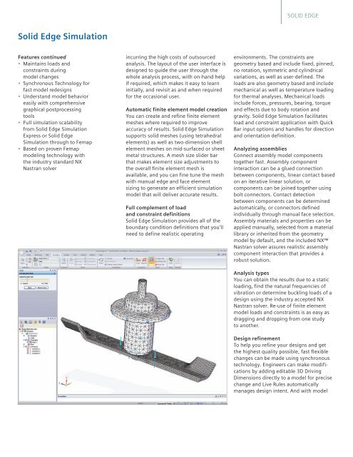
SOLID EDGE<strong>Solid</strong> <strong>Edge</strong> <strong>Simulation</strong>Features continued• Maintains loads andconstraints duringmodel changes• Synchronous Technology forfast model redesigns• Understand model behavioreasily with comprehensivegraphical postprocessingtools• Full simulation scalabilityfrom <strong>Solid</strong> <strong>Edge</strong> <strong>Simulation</strong>Express or <strong>Solid</strong> <strong>Edge</strong><strong>Simulation</strong> through to Femap• Based on proven Femapmodeling technology withthe industry standard NXNastran solverincurring the high costs of outsourcedanalysis. The layout of the user interface isdesigned to guide the user through thewhole analysis process, with on-hand helpif required, which makes it easy to learninitially, and revisit as and when requiredfor the occasional user.Automatic finite element model creationYou can create and refine finite elementmeshes where required to improveaccuracy of results. <strong>Solid</strong> <strong>Edge</strong> <strong>Simulation</strong>supports solid meshes (using tetrahedralelements) as well as two-dimension shellelement meshes on mid-surfaced or sheetmetal structures. A mesh size slider barthat makes element size adjustments tothe overall finite element mesh isavailable, and you can fine tune the meshwith manual edge and face elementsizing to generate an efficient simulationmodel that will deliver accurate results.Full complement of loadand constraint definitions<strong>Solid</strong> <strong>Edge</strong> <strong>Simulation</strong> provides all of theboundary condition definitions that you’llneed to define realistic operatingenvironments. The constraints aregeometry based and include fixed, pinned,no rotation, symmetric and cylindricalvariations, as well as user-defined. Theloads are also geometry based and includemechanical as well as temperature loadingfor thermal analyses. Mechanical loadsinclude forces, pressures, bearing, torqueand effects due to body rotation andgravity. <strong>Solid</strong> <strong>Edge</strong> <strong>Simulation</strong> facilitatesload and constraint application with QuickBar input options and handles for directionand orientation definition.Analyzing assembliesConnect assembly model componentstogether fast. Assembly componentinteraction can be a glued connectionbetween components, linear contact basedon an iterative linear solution, orcomponents can be joined together usingbolt connectors. Contact detectionbetween components can be determinedautomatically, or connectors definedindividually through manual face selection.Assembly materials and properties can beapplied manually, selected from a materiallibrary or inherited from the geometrymodel by default, and the included NXNastran solver assures realistic assemblycomponent interaction that provides arobust solution.Analysis typesYou can obtain the results due to a staticloading, find the natural frequencies ofvibration or determine buckling loads of adesign using the industry accepted NXNastran solver. Re-use of finite elementmodel loads and constraints is as easy asdragging and dropping from one studyto another.Design refinementTo help you refine your designs and getthe highest quality possible, fast flexiblechanges can be made using synchronoustechnology. Engineers can make modificationsby adding editable 3D DrivingDimensions directly to a model for precisechange and Live Rules automaticallymanages design intent. And with model