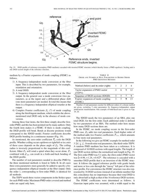
352 IEEE JOURNAL OF SELECTED TOPICS IN QUANTUM ELECTRONICS, VOL. 10, NO. 2, MARCH/APRIL 2004Fig. 19. DGD profile of reference (exemplary <strong>PMD</strong> medium) cascaded with <strong>in</strong>verted FEMC structure (which thereby <strong>for</strong>ms a <strong>PMD</strong> equilizer). Scal<strong>in</strong>g unit isone DGD section length of the reference structure.medium by a Fourier expansion of mode coupl<strong>in</strong>g (FEMC) asfollows.1) A frequency-<strong>in</strong>dependent mode conversion at the fiber<strong>in</strong>put. This is described by two parameters, <strong>for</strong> example,retardation <strong>and</strong> orientation.2) A total DGD.3) A frequency-<strong>in</strong>dependent mode conversion at the fiberoutput. In the general case a mode conversion (two parameters,as at the <strong>in</strong>put) <strong>and</strong> a differential phase shift(one more parameter) are needed. In total this means thatthere is a frequency-<strong>in</strong>dependent elliptical retarder at theoutput.4) Complex Fourier coefficients (7) of mode coupl<strong>in</strong>galong the birefr<strong>in</strong>gent medium, which exhibits the abovementionedtotal DGD only <strong>in</strong> the absence of mode conversion.Among these four items, the first three simply describe firstorder<strong>PMD</strong>, <strong>and</strong> this has been po<strong>in</strong>ted out by many authors. Onlythe fourth item makes it a FEMC. If there is mode coupl<strong>in</strong>g,the DGD profile will bend. Bends at discrete positions wouldcorrespond to the SDGD model. Fourier coefficients describeDGD profile bend<strong>in</strong>g <strong>in</strong> a cont<strong>in</strong>uous manner (Fig. 19).As mentioned, the zero-order coefficient coils the DGDprofile. Whether coil<strong>in</strong>g occurs up/down or right/left or <strong>in</strong> a mixof these cases depends on the phase angle of . The coil<strong>in</strong>gradius is <strong>in</strong>versely proportional to the magnitude of this coefficient.Other will w<strong>in</strong>d a spiral when they occur alone.comb<strong>in</strong>ed with can result <strong>in</strong> a <strong>for</strong>th-<strong>and</strong>-back bend<strong>in</strong>g ofthe DGD profile.The number of real parameters needed to describe <strong>PMD</strong> bythe three mentioned methods is listed <strong>in</strong> Table II. In all casesthree extra parameters must generally be added to specify a frequency-<strong>in</strong>dependentelliptical retarder at the fiber output. Onlythe order 1, correspond<strong>in</strong>g to first-order <strong>PMD</strong>, is identical <strong>for</strong>all methods.The TEPV needs three vector components <strong>in</strong> the Stokes space<strong>for</strong> each <strong>PMD</strong> order. Maximum <strong>PMD</strong> order covered <strong>and</strong> methodorder are equal only here.TABLE IIORDER AND NUMBER OF REAL PARAMETERS IN HIGHER ORDER<strong>PMD</strong> DEFINITION METHODSThe SDGD needs the two parameters of an SBA, plus onetotal DGD, <strong>for</strong> the first order. Each additional order is def<strong>in</strong>edby two parameters of an SBA. The method order here meanshow many DGD sections there are.In the FEMC, no mode coupl<strong>in</strong>g occurs <strong>in</strong> the first-order<strong>PMD</strong> case. adds two real parameters. Each higher order ofthe method adds two Fourier coefficients , which amountsto four more real parameters.In the follow<strong>in</strong>g we give an FEMC example <strong>for</strong> method order3 . It needs n<strong>in</strong>e real parameters, like third-order TEPV.A r<strong>and</strong>om <strong>PMD</strong> medium has been taken as a reference. It iscomposed of 16 DGD sections with equal lengths. The length ofone DGD section def<strong>in</strong>es the normalized unit length <strong>in</strong> Fig. 19.The first-order <strong>PMD</strong> was 5.1 units, the (first-order) <strong>PMD</strong> vectorwas 4.98 1.24 0.42 . The reference is cascaded with asmoother DGD profile that is an <strong>in</strong>version of the FEMC structure.It follows the jagged reference profile with gentle bends<strong>and</strong> more or less cuts through the “messy” left part of the referenceprofile. For convenience the FEMC structure was also representedby 16 DGD sections (<strong>in</strong>stead of an <strong>in</strong>f<strong>in</strong>ite number) butthis co<strong>in</strong>cidence has no importance because their total DGD isonly about half as high as that of the 16 reference DGD sections.The FEMC coefficients were determ<strong>in</strong>ed as follows. AGaussian <strong>in</strong>put pulse was assumed, with a width equal to theAuthorized licensed use limited to: UNIVERSITATSBIBLIOTHEK PADERBORN. Downloaded on May 18,2010 at 07:51:58 UTC from IEEE Xplore. Restrictions apply.
NOÉ et al.: <strong>PMD</strong> IN HIGH-BIT-RATE TRANSMISSION 353TABLE IIISUPPRESSION OF CROSS POLARIZATION BY EQUALIZERS DEFINED BYHIGHER-ORDER <strong>PMD</strong> DEFINITION METHODSFig. 20. Magnitudes of Gaussian <strong>in</strong>put pulse <strong>and</strong> of output pulses result<strong>in</strong>gfrom cascaded reference <strong>and</strong> <strong>in</strong>verted FEMC structure. Time scale is the sameas <strong>in</strong> Fig. 19. Input pulse width is 8.07 DGD units.total DGD of the DGD profile used <strong>in</strong> the FEMC (assum<strong>in</strong>g nomode conversion). This is not the only possible FEMC pulseshape <strong>and</strong> duration. However, it makes sense to choose thetotal DGD rather than the first-order DGD because the <strong>for</strong>meris related to the overall complexity of the <strong>PMD</strong> situation, whilethe latter may even disappear. Pulse width <strong>and</strong> the identical totalDGD were of course varied dur<strong>in</strong>g the optimization. The <strong>PMD</strong>medium (reference) <strong>and</strong> the <strong>in</strong>verse of the structure def<strong>in</strong>ed bythe FEMC were concatenated. The various parameters wereadjusted so that the output signal was—as far as possible—<strong>in</strong>only one (co)polarization mode, <strong>and</strong> that the impulse <strong>in</strong> theother (cross-)polarization had its residual maximum amplitudenear the time orig<strong>in</strong>, not elsewhere like <strong>in</strong> the case of first-order<strong>PMD</strong>. Fig. 20 shows the magnitudes of the electric fields <strong>in</strong> co<strong>and</strong>cross-polarized output pulses. The unwanted polarizationis37.2 dB down. The Gaussian <strong>in</strong>put pulse is also shown.As an alternative to the FEMC, the SDGD method could describethe reference profile exactly, but only if it comprised 16sections equal to those of the reference.For comparison, the TEPV method was also tested. TheTEPV was calculated up to the third order from the Jonesmatrix of the reference (<strong>PMD</strong> medium). Then, the Jones matrixcorrespond<strong>in</strong>g to this truncated TEPV was built as described <strong>in</strong>[57]. As a third c<strong>and</strong>idate, the EMTY method, an exponentialexpansion of the Jones matrix by Eyal, Marshall, Tur, <strong>and</strong> Yariv[61],[62] was tested the same way. For all methods, the <strong>in</strong>putpulse width was chosen identical to that after convergence ofthe FEMC. Table III shows orthogonal polarization suppressionversus method <strong>and</strong> its order. In the given example, the FEMCholds an advantage over the TEPV ad the EMTY method. Theext<strong>in</strong>ction improvement <strong>in</strong> dB after addition of higher-orderterms is several times larger <strong>for</strong> FEMC than <strong>for</strong> TEPV <strong>and</strong>EMTY. In a few more tested <strong>PMD</strong> examples, the FEMC alsoheld an advantage. This is not surpris<strong>in</strong>g because the FEMC<strong>and</strong> SDGD models are closely related to natural <strong>PMD</strong>.However, more work is needed to assess whether (<strong>and</strong> howmuch) the FEMC outper<strong>for</strong>ms the TEPV (<strong>and</strong> the EMTYmethod) on average. If he answer is yes, then a <strong>PMD</strong>C thatcould, <strong>for</strong> example, compensate the traditional <strong>PMD</strong> orders1 to 3, might not be the most efficient equalizer. Rather,a distributed <strong>PMD</strong>C could be preferable, with as sharp aspossible a polarization trans<strong>for</strong>mation at its <strong>in</strong>put, with onemore at the output if a def<strong>in</strong>ed output polarization is needed,<strong>and</strong> controlled amounts of mode coupl<strong>in</strong>g along its length, <strong>for</strong>example, def<strong>in</strong>ed by Fourier coefficients.In its realization the distributed <strong>PMD</strong>C has a fixed total DGD.So its DGD profile must be flexible enough to fold, <strong>in</strong> order toelim<strong>in</strong>ate any excess DGD.Note that <strong>for</strong> the calculations of Table III, three more parametersthan shown <strong>in</strong> Table II were chosen because the “equalizer”needed to be aligned to the reference to separate the polarizationsas shown <strong>in</strong> Fig. 20.Several variations of the FEMC are conceivable. Forexample, <strong>in</strong>stead of the Fourier coefficients withorders, one could use the orders. This would mean that the numbers<strong>in</strong> the last l<strong>in</strong>e of Table II would need to be replaced by 3,7, 11, <strong>and</strong> 15. Alternatively, the <strong>in</strong>put <strong>and</strong> output polarizationtrans<strong>for</strong>mers could be made part of the mode conversionprocess. This is also practically the case if a distributed <strong>PMD</strong>Cis used <strong>for</strong> <strong>PMD</strong> compensation plus output polarization control.Determ<strong>in</strong><strong>in</strong>g the <strong>and</strong> other FEMC coefficients presently<strong>in</strong>volves the described numerical m<strong>in</strong>imization process. It may<strong>in</strong>deed be considered as the most important drawback of this<strong>PMD</strong> description method that an analytical solution is notknown. F<strong>in</strong>d<strong>in</strong>g an easy solution might help <strong>in</strong> the control ofdistributed <strong>PMD</strong>Cs—this is a question of not gett<strong>in</strong>g trapped <strong>in</strong>local optima dur<strong>in</strong>g the <strong>PMD</strong> control process.The SDGD method is conceptually similar to FEMC <strong>and</strong> canbe an alternative to FEMC, maybe by keep<strong>in</strong>g the DGD sectionlengths constant <strong>and</strong> vary<strong>in</strong>g their number.VI. CONCLUSIONResearch on <strong>PMD</strong> mitigation <strong>and</strong> compensation issues is stillwide open, only with the str<strong>in</strong>gent constra<strong>in</strong>t of cost. Interest<strong>in</strong>gtopics are <strong>in</strong> particular:• electronic <strong>PMD</strong> mitigation at 40 Gbit/s;• higher order <strong>PMD</strong> detection <strong>for</strong> alternative signal <strong>and</strong>modulation <strong>for</strong>mats;• fabrication of distributed <strong>PMD</strong> compensators <strong>in</strong> LiNbO ;• fast endless polarization control.Progress on these items is still needed <strong>for</strong> a fast, accurate, <strong>and</strong>sufficiently cheap <strong>PMD</strong> compensation at 40-Gbit/s speeds.Authorized licensed use limited to: UNIVERSITATSBIBLIOTHEK PADERBORN. Downloaded on May 18,2010 at 07:51:58 UTC from IEEE Xplore. Restrictions apply.