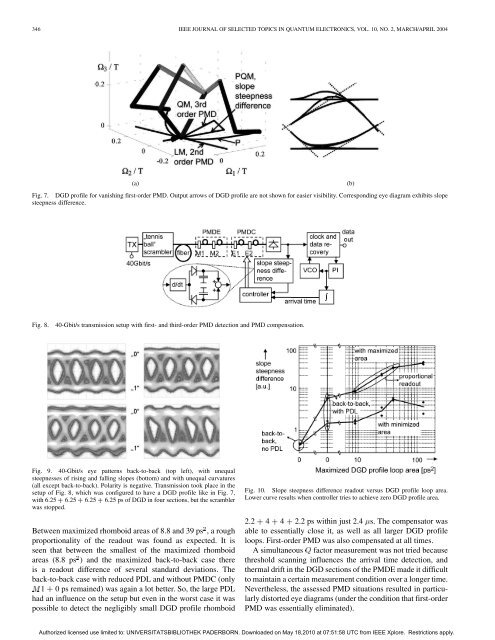
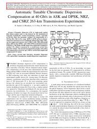
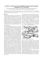
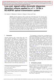
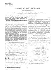
346 IEEE JOURNAL OF SELECTED TOPICS IN QUANTUM ELECTRONICS, VOL. 10, NO. 2, MARCH/APRIL 2004(a)(b)Fig. 7. DGD profile <strong>for</strong> vanish<strong>in</strong>g first-order <strong>PMD</strong>. Output arrows of DGD profile are not shown <strong>for</strong> easier visibility. Correspond<strong>in</strong>g eye diagram exhibits slopesteepness difference.Fig. 8.40-Gbit/s transmission setup with first- <strong>and</strong> third-order <strong>PMD</strong> detection <strong>and</strong> <strong>PMD</strong> compensation.Fig. 9. 40-Gbit/s eye patterns back-to-back (top left), with unequalsteepnesses of ris<strong>in</strong>g <strong>and</strong> fall<strong>in</strong>g slopes (bottom) <strong>and</strong> with unequal curvatures(all except back-to-back). Polarity is negative. <strong>Transmission</strong> took place <strong>in</strong> thesetup of Fig. 8, which was configured to have a DGD profile like <strong>in</strong> Fig. 7,with 6.25 + 6.25 + 6.25 + 6.25 ps of DGD <strong>in</strong> four sections, but the scramblerwas stopped.Between maximized rhomboid areas of 8.8 <strong>and</strong> 39 ps , a roughproportionality of the readout was found as expected. It isseen that between the smallest of the maximized rhomboidareas (8.8 ps ) <strong>and</strong> the maximized back-to-back case thereis a readout difference of several st<strong>and</strong>ard deviations. Theback-to-back case with reduced PDL <strong>and</strong> without <strong>PMD</strong>C (only1 0 ps rema<strong>in</strong>ed) was aga<strong>in</strong> a lot better. So, the large PDLhad an <strong>in</strong>fluence on the setup but even <strong>in</strong> the worst case it waspossible to detect the negligibly small DGD profile rhomboidFig. 10. Slope steepness difference readout versus DGD profile loop area.Lower curve results when controller tries to achieve zero DGD profile area.2.2 4 4 2.2 ps with<strong>in</strong> just 2.4 s. The compensator wasable to essentially close it, as well as all larger DGD profileloops. First-order <strong>PMD</strong> was also compensated at all times.A simultaneous factor measurement was not tried becausethreshold scann<strong>in</strong>g <strong>in</strong>fluences the arrival time detection, <strong>and</strong>thermal drift <strong>in</strong> the DGD sections of the <strong>PMD</strong>E made it difficultto ma<strong>in</strong>ta<strong>in</strong> a certa<strong>in</strong> measurement condition over a longer time.Nevertheless, the assessed <strong>PMD</strong> situations resulted <strong>in</strong> particularlydistorted eye diagrams (under the condition that first-order<strong>PMD</strong> was essentially elim<strong>in</strong>ated).Authorized licensed use limited to: UNIVERSITATSBIBLIOTHEK PADERBORN. Downloaded on May 18,2010 at 07:51:58 UTC from IEEE Xplore. Restrictions apply.
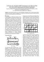
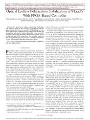
NOÉ et al.: <strong>PMD</strong> IN HIGH-BIT-RATE TRANSMISSION 347IV. OPTICAL <strong>PMD</strong> COMPENSATIONA. Devices <strong>and</strong> MethodsBe<strong>for</strong>e specializ<strong>in</strong>g on one <strong>PMD</strong> compensation device <strong>and</strong>method we review here some work <strong>in</strong> this field.Inside an optical <strong>PMD</strong>C with cascaded DGD sections eachof its polarization trans<strong>for</strong>mers must be able to endlessly trans<strong>for</strong>many <strong>in</strong>put polarization <strong>in</strong>to a pr<strong>in</strong>cipal state-of-polarizationof the subsequent differential group delay section [7].Endless track<strong>in</strong>g means that polarization fluctuations may atany po<strong>in</strong>t <strong>in</strong> the fiber l<strong>in</strong>k go around the Po<strong>in</strong>caré spheremore than once, possibly an <strong>in</strong>f<strong>in</strong>ite number of times. Thisis a much more difficult task than polarization control withlimited control range: For any polarization trans<strong>for</strong>mer, thetrack<strong>in</strong>g of certa<strong>in</strong> small polarization fluctuations will requirelarge drive signal changes. For example, when an electroopticSoleil–Bab<strong>in</strong>et compensator [33] (rotatable waveplate with adjustableretardation) with circular <strong>in</strong>put polarization reaches aretardation angle of while the output polarization marchesstraight through the po<strong>in</strong>t of circular retardation, then it mustchange its orientation angle by ; else the retardation angle<strong>and</strong> the required driv<strong>in</strong>g voltages will keep <strong>in</strong>creas<strong>in</strong>g, eventuallydestroy<strong>in</strong>g the device.Polarization trans<strong>for</strong>mers with retarders hav<strong>in</strong>g fixed eigenmodesare more complicated to control. Procedures are necessarywhere a retardation is typically reset by 2 under cooperationof other retarders to keep the output polarization unchanged[34]. Fiber squeezers <strong>and</strong> most k<strong>in</strong>ds of liquid crystal cells belongto this class. The track<strong>in</strong>g speed that can be achieved ism<strong>in</strong>imum if the absolute value of the retardation is not stable.Stability is usually not specified by manufacturers. Even whenthe retardation is stable the safe endless track<strong>in</strong>g speed is just0.033 rad/iteration [42]. We there<strong>for</strong>e see the potential of suchretarders <strong>for</strong> <strong>PMD</strong> compensation as quite critical. For comb<strong>in</strong>ationwith a high-speed controller, we believe the response timeshould be on the order of 5 s or less.All polarization trans<strong>for</strong>mers can be operated as endless deviceseven without stable retardation if there are many of them.However, the speed penalty paid <strong>for</strong> this simplification is dramatic.A workhorse <strong>for</strong> a lot of experimental <strong>PMD</strong> compensationwork are electrooptic waveplates <strong>in</strong> -cut, -propagationLiNbO . These devices are not birefr<strong>in</strong>gent <strong>and</strong> have a wideoptical b<strong>and</strong>width. The response is <strong>in</strong>creased by a f<strong>in</strong>ite bufferlayer isolation, but is there<strong>for</strong>e not fully <strong>in</strong>stantaneous.In addition to endless control of one variable polarizaitonwith an electrooptic Soleil–Bab<strong>in</strong>et compensator [33] twoSoleil–Bab<strong>in</strong>et compensators [43] or three waveplates [44]have been used to trans<strong>for</strong>m any <strong>in</strong>put <strong>in</strong>to any output polarization.Devices where the waveguide birefr<strong>in</strong>gence is tuned outcompletely by a slight off-axis propagation can be operated withlow offset voltages. But the waveguide exhibits a reciprocalcircular retardation. Another issue is dc drift [45]: Chargesgenerated by the pyroelectric effect are separated under the<strong>in</strong>fluence of a static external electric field, thereby weaken<strong>in</strong>gthis field <strong>in</strong>side <strong>and</strong> near the waveguide. Ion migration <strong>in</strong> thebuffer layer <strong>and</strong>/or conductivity disturbances of the crystalFig. 11. 20-Gbit/s eye diagrams (a) back-to-back, (b) with emulator <strong>and</strong> idle<strong>PMD</strong>Cs (unusually good here), (c) with emulator <strong>and</strong> work<strong>in</strong>g <strong>PMD</strong>Cs, <strong>and</strong> (d)with <strong>PMD</strong>Cs alone.Fig. 12. Elementary <strong>in</strong>-phase <strong>and</strong> quadrature mode converter (one section) <strong>in</strong>x-cut, y-propagation LiNbO .cause a similar effect. DC drift limits are not known or at leastnot specified <strong>for</strong> commercial -cut, -propagation LiNbOpolarization trans<strong>for</strong>mers. The dc drift lets the retardationoffset calibration drift slowly with time, <strong>and</strong> this is the biggestproblem.Polarization controllers made of any other materials thanLiNbO are less suitable <strong>in</strong> our op<strong>in</strong>ion.B. Distributed <strong>PMD</strong> CompensatorRegard<strong>in</strong>g cost <strong>and</strong> space, the <strong>in</strong>tegratability of several polarizationtrans<strong>for</strong>mers <strong>and</strong> DGD sections <strong>in</strong>to one device is decisive.This requirement, <strong>and</strong> most others, are best fulfilled <strong>in</strong> adistributed <strong>PMD</strong>C. In a preparatory attempt a weakly polarization-ma<strong>in</strong>ta<strong>in</strong><strong>in</strong>gfiber with a total DGD of 77 ps was twisted at64 positions. This resulted <strong>in</strong> successful <strong>PMD</strong> compensation at20 Gbit/s [7].Later the pr<strong>in</strong>ciple was implemented <strong>in</strong> an -cut, -propagationLiNbO chip. At 20 Gbit/s, 10 20 ps of DGD were compensatedby two cascaded distributed LiNbO <strong>PMD</strong>Cs with atotal DGD of 43 ps [46]. Correspond<strong>in</strong>g eye diagrams are shown<strong>in</strong> Fig. 11. The device was also tested at 40 Gbit/s [47].In the follow<strong>in</strong>g we will concentrate on recent progress withthese devices [48], [49]. Fig. 12 shows a basic polarization trans<strong>for</strong>mer,an <strong>in</strong>-phase <strong>and</strong> quadrature mode converter as proposedby Heismann <strong>and</strong> Ulrich [50]. Several or many of them are cascaded<strong>in</strong> a distributed <strong>PMD</strong>C. Comb-shaped mode converterelectrodes are distributed along a birefr<strong>in</strong>gent waveguide.The electrode period equals the TE-TM beat length(22 m at 1550 nm). This mode converter may be called aSoleil–Bab<strong>in</strong>et analog SBA [7] because of the analogyto a Soleil–Bab<strong>in</strong>et compensator: What the Soleil–Bab<strong>in</strong>etcompensator does with circular, the SBA can do with horizontal/verticalpolarizations. It is described by a Jones matrixAuthorized licensed use limited to: UNIVERSITATSBIBLIOTHEK PADERBORN. Downloaded on May 18,2010 at 07:51:58 UTC from IEEE Xplore. Restrictions apply.