Fretting Fatigue of Slot-dovetails in Turbo-generator Rotor
Fretting Fatigue of Slot-dovetails in Turbo-generator Rotor
Fretting Fatigue of Slot-dovetails in Turbo-generator Rotor

Create successful ePaper yourself
Turn your PDF publications into a flip-book with our unique Google optimized e-Paper software.
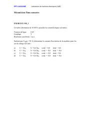
<strong>Frett<strong>in</strong>g</strong> <strong>Fatigue</strong> <strong>of</strong> <strong>Slot</strong>-<strong>dovetails</strong> <strong>in</strong> <strong>Turbo</strong>-<strong>generator</strong> <strong>Rotor</strong>(From O&M Issues Discussed <strong>in</strong> Recent EPRI Meet<strong>in</strong>gs)H. ItoToshiba Corporation1-1-1, Shibaura, M<strong>in</strong>ato-Ku, Tokyo, 105-8001 JapanAbstract-This paper describes the frett<strong>in</strong>g fatigue <strong>of</strong> slot<strong>dovetails</strong><strong>in</strong> turbo-<strong>generator</strong> rotor <strong>in</strong>clud<strong>in</strong>g typical examples andrepairs <strong>of</strong> frett<strong>in</strong>g fatigue cracks, results <strong>of</strong> frett<strong>in</strong>g fatigue tests,factors affect<strong>in</strong>g frett<strong>in</strong>g fatigue strength, frett<strong>in</strong>g fatiguepreventive technologies, and UT <strong>in</strong>spection methods.I INTRODUCTIONIn the ‘70s, two 660 MW turbo-<strong>generator</strong>s <strong>in</strong> Europeexperienced shaft crack<strong>in</strong>g due to frett<strong>in</strong>g fatigue <strong>of</strong> the slot<strong>dovetails</strong>.The authors started the basic study <strong>of</strong> frett<strong>in</strong>gfatigue <strong>of</strong> the shaft slot-<strong>dovetails</strong> <strong>in</strong> the late ‘70s. Inspectionresults showed that <strong>generator</strong> shafts, manufactured by theauthors, also cracked <strong>in</strong> the slot-<strong>dovetails</strong>. High-speed fatiguetest equipment was <strong>in</strong>troduced to perform comprehensivefrett<strong>in</strong>g fatigue tests simulat<strong>in</strong>g actual mach<strong>in</strong>es. The authorssucceeded <strong>in</strong> quantitatively def<strong>in</strong><strong>in</strong>g dom<strong>in</strong>ant factors affect<strong>in</strong>gfrett<strong>in</strong>g fatigue strength <strong>of</strong> slot-<strong>dovetails</strong> <strong>of</strong> turbo-<strong>generator</strong>rotor.A frett<strong>in</strong>g fatigue preventive technology was established forthe slot-<strong>dovetails</strong> based on the test results and review. Anondestructive <strong>in</strong>spection technology us<strong>in</strong>g UT was alsodeveloped. The frett<strong>in</strong>g fatigue preventive technology hasadopted <strong>in</strong> the new mach<strong>in</strong>es as a standard design application.It is also used <strong>in</strong> the <strong>in</strong>stalled mach<strong>in</strong>es as refurbishment. Themach<strong>in</strong>es with applied by these technologies are successfullyoperat<strong>in</strong>g for more than 20 years s<strong>in</strong>ce application.This paper <strong>in</strong>troduces examples and repairs <strong>of</strong> slot-dovetailfrett<strong>in</strong>g fatigue cracks, results <strong>of</strong> frett<strong>in</strong>g fatigue tests, factorsaffect<strong>in</strong>g frett<strong>in</strong>g fatigue strength, frett<strong>in</strong>g fatigue preventivetechnologies, UT <strong>in</strong>spection technology, and application <strong>of</strong>frett<strong>in</strong>g fatigue preventive technology to the <strong>in</strong>stalled mach<strong>in</strong>es.IIEXPERIENCES OF INSPECTION, CRACKED ROTOR SLOT-DOVETAIL AND REPAIRFig. 1 shows experience <strong>of</strong> <strong>in</strong>spections and observed crackedslot-<strong>dovetails</strong> s<strong>in</strong>ce 1979 by year. N<strong>in</strong>e out <strong>of</strong> 601 <strong>in</strong>spectedrotors were found to have cracks. Table 1 shows operat<strong>in</strong>ghistory, description <strong>of</strong> cracks and repairs, and countermeasures.As a severe example, mach<strong>in</strong>e A* is described below <strong>in</strong> detail<strong>in</strong>clud<strong>in</strong>g crack pr<strong>of</strong>ile, repair and countermeasure.Number <strong>of</strong> Inspected <strong>Rotor</strong>Unit4035302520151050■ ; Cracked <strong>Rotor</strong> <strong>Slot</strong>-dovetail1980 1985 1990 1995 2000Inspection YearFig. 1 Experience <strong>of</strong> Inspection and Cracked <strong>Rotor</strong> <strong>Slot</strong>-dovetailYear <strong>of</strong>InspectionTable 1. Experiences <strong>of</strong> Cracked <strong>Rotor</strong> <strong>Slot</strong>-dovetailOut-put(MW)Year <strong>in</strong>serviceA 1981 220 1963B 1982 350 1972C 1982 250 1971D 1982 500 1968E 1983 600 1973F 1987 350 1972G 1990 500 1973A* 1990 220 1963H 1991 375 1973Description <strong>of</strong> Crack<strong>in</strong>gCrack size: L10 x D3.2 mmCrack position: About the core centerNo. <strong>of</strong> cracks: 1Wedge hardness: Equal to shaftOperation hours: 100,000hNo. <strong>of</strong> starts and stops: 766Crack size (max.): L3.5 x D0.98 mmCrack position: About the core centerNo. <strong>of</strong> cracks: 10Wedge hardness: Harder than shaftCrack size: L2.5 mmCrack position: About the core centerNo. <strong>of</strong> cracks: 1Crack size (max.): L6.6 x 1.5 mmNo. cracks: 55Wedge hardness: Equal to or harder than shaftCrack size: L4.5 x D1.4 mmNo. <strong>of</strong> cracks: 9Wedge hardness: Equal to shaftCrack size: L4.0 mmNo. <strong>of</strong> cracks: 3Wedge hardness: Shaft is harderCrack size: L4.0 mmNo. <strong>of</strong> cracks: 28Wedge hardness: Shaft is harderCrack size: L23 x D8.5 mmNo. <strong>of</strong> cracks: 2Crack size: L5.5 mmNo. <strong>of</strong> cracks: 3Repair / ModificationGr<strong>in</strong>d <strong>of</strong>f cracks.Increase corner radius at wedge shoulder.Replace with wedges <strong>of</strong> a lower hardness.Gr<strong>in</strong>d <strong>of</strong>f cracks.Increase corner radius at wedge shoulder.Replace with wedges <strong>of</strong> a lower hardness.Clear<strong>in</strong>g <strong>of</strong> Crack<strong>in</strong>g with Gra<strong>in</strong>der.Make taper with radius at end <strong>of</strong> wedgeshoulder.Gr<strong>in</strong>d <strong>of</strong>f cracks.Increase corner radius at wedge shoulder.Replace with wedges <strong>of</strong> a lower hardness.Gr<strong>in</strong>d <strong>of</strong>f cracks.Increase corner radius at wedge shoulder.Replace with wedges <strong>of</strong> a lower hardness.Gr<strong>in</strong>d <strong>of</strong>f cracks.Increase corner radius at wedge shoulder.Replace with wedges <strong>of</strong> a lower hardness.Gr<strong>in</strong>d <strong>of</strong>f cracks.Increase corner radius at wedge shoulder.Gr<strong>in</strong>d <strong>of</strong>f cracks.Replace with alum<strong>in</strong>um alloy wedges.Change wedge length and arrangement.Gr<strong>in</strong>d <strong>of</strong>f cracks.Increase corner radius at wedge shoulder.Two cracks were observed at the core center <strong>of</strong> the slots bythe pole on the jo<strong>in</strong>t <strong>of</strong> steel wedges. A larger one measured 23mm <strong>in</strong> length and 8.5 mm <strong>in</strong> depth. Fig. 2 shows the crack <strong>in</strong>detail. The cracks were ground <strong>of</strong>f to suitable shapes to preventstress concentration and the surface was smoothly f<strong>in</strong>ished (Fig.3). Wedges were bridged over the ground <strong>of</strong>f area. The wedgematerial was changed from steel to alum<strong>in</strong>um alloy.Concentration <strong>of</strong> contact pressure was avoided by <strong>in</strong>creas<strong>in</strong>g thecorner radius on the area where the wedge edge contacts the slot<strong>dovetails</strong>. The unit is runn<strong>in</strong>g for 10 years s<strong>in</strong>ce then withoutproblems.1
108.585Crack<strong>in</strong>gequipment. The specimen is made <strong>of</strong> Ni-Cr-Mo-V steel, which isthe same as the shaft material. The pad is made <strong>of</strong> S55C(quenched and tempered) (AISI-1055), which is the same as thematerial <strong>of</strong> steel wedge. Table 2 and 3 show chemistry andmechanical properties <strong>of</strong> materials <strong>of</strong> specimen and pad,respectively.Fig 2. Detailed Cracked <strong>Rotor</strong> <strong>Slot</strong>-dovetail <strong>of</strong> A* Unit(10)(16)Fig. 4 Schematic Illustration <strong>of</strong> <strong>Frett<strong>in</strong>g</strong> <strong>Fatigue</strong> Test MethodFig 3.Repair and Correction for A* UnitIII EXPERIMENTAL STUDIES<strong>Frett<strong>in</strong>g</strong> fatigue <strong>of</strong> turb<strong>in</strong>e and turbo-<strong>generator</strong> rotors havebeen studied by many researchers for many years. Areas <strong>of</strong>concern are blade roots and coupl<strong>in</strong>g-to-shaft shr<strong>in</strong>kage fit. Theconventional frett<strong>in</strong>g fatigue tests used only one pad andadjacent wedges such as <strong>in</strong> the slot-<strong>dovetails</strong> <strong>of</strong> a turbo<strong>generator</strong>shaft were not simulated.We developed a high-speed fatigue test<strong>in</strong>g equipment<strong>in</strong>corporat<strong>in</strong>g two double-pads that simulate actual arrangements<strong>of</strong> wedges <strong>in</strong> slot-<strong>dovetails</strong>. We quantitatively evaluated factorsaffect<strong>in</strong>g frett<strong>in</strong>g fatigue strength <strong>of</strong> slot-<strong>dovetails</strong>. Theevaluated factors <strong>in</strong>cluded proximity effect <strong>of</strong> pads (wedges),contact pressure, relative slippage (wedge length), pad (wedge)materials (hardness, Young’s modulus, rigidity) and repeatedstress (shaft bend<strong>in</strong>g stress).We studied the frett<strong>in</strong>g fatigue preventive measures andfatigue life evaluation method for slot-<strong>dovetails</strong> based on the testresults and review.Test Equipment and MethodFig. 4 shows a schematic test arrangement <strong>of</strong> the frett<strong>in</strong>gfatigue test<strong>in</strong>g system. Fig. 4-(a) and 4-(b) are conventionaltest<strong>in</strong>g systems. Fig. 4-(c) is the double-pad type test system,which is newly devised to def<strong>in</strong>e the proximity effects <strong>of</strong>wedges. Fig. 5 shows a specimen and a pad. Fig. 6 illustratesthe test<strong>in</strong>g equipment. Fig. 7 is a photograph <strong>of</strong> the testFig. 5 Specimen and PadFig. 6 <strong>Frett<strong>in</strong>g</strong> <strong>Fatigue</strong> Test Equipment2
SpecimenPadFig. 8 Specimen and Pad for Pad Materials Effect TestFig. 7 Photograph <strong>of</strong> Setup <strong>of</strong> <strong>Frett<strong>in</strong>g</strong> <strong>Fatigue</strong> Test<strong>in</strong>gTable 2 Chemical Composition <strong>of</strong> Specimen and PadC Si Mn P S Ni Cr Mo VSpeci 0.24 0.10 0.32 0.00 0.00 3.71 1.60 0.27 0.12men7 5Pad 0.56 0.21 0.75 0.01 0.01 - - - -Table 3 Mechanical Properties <strong>of</strong> Specimen and PadReduction0.2% pro<strong>of</strong> Tensile ElongationHardness<strong>of</strong> areastress MPa stress MPa %Hv (1.0kg)%Specimen 790 895 25.3 71.3 269Pad 634(*) 811 19.5 39.6 265(*) Yield stress<strong>Frett<strong>in</strong>g</strong> fatigue tests were conducted <strong>in</strong> the atmospheric air atroom temperature with load control <strong>of</strong> pulsat<strong>in</strong>g tension at 15Hz. Pad clearance C was 0.25 and 4 mm and <strong>in</strong>f<strong>in</strong>ity (s<strong>in</strong>glepad). Nom<strong>in</strong>al contact pressure was 50, 100 and 200(equivalentto actual mach<strong>in</strong>es) MPa. Relative slippage <strong>of</strong> the pad edge was5 to 6 µm (equivalent to actual mach<strong>in</strong>es).<strong>Fatigue</strong> tests to evaluate the effect <strong>of</strong> pad materials wereconducted us<strong>in</strong>g the specimens and pads shown <strong>in</strong> Fig. 8 and thetest<strong>in</strong>g equipment shown <strong>in</strong> Fig. 9. The specimen materials wereNi-Cr-Mo-V steels or the same as the above specimens. The padmaterials tested were 5 each ferrous and nonferrous materials asshown <strong>in</strong> Table 4.<strong>Fatigue</strong> tests were conducted <strong>in</strong> the atmospheric air at roomtemperature with load control <strong>of</strong> pulsat<strong>in</strong>g tension at 100 Hz.Nom<strong>in</strong>al contact pressure was 200 MPa constant.Fig. 9 Test Equipment for Pad Materials Effect TestTable 4 Mechanical Properties <strong>of</strong> Pads for Pad Materials Effect TestContact pad σ 0.2 σ u δ ϕ E σ wfHvμmaterial MPa MPa % % GPa MPa3.5NiCrMoV-QT 790 895 25.3 71.3 269 205 0.7 753.5NiCrMoV-Q 1103 1660 13.7 46.4 403 207 0.7 80S55C-QT 561 933 21.5 45 255 201 0.68 75S25C-N 231 430 27.7 58.1 195 201 0.7 90SUS304 247 663 69.9 81 200 190 0.7 80Cu-Be-Ni 507 760 15.5 31.5 239 130 0.55 100Cu-Cr 380 450 26 51.2 150 120 0.65 130Cu 245 264 30 85 102 110 0.65 140A2024-T351 296 477 13.7 17.2 141 75 0.7 130Ti-6Al-4V 941 1035 15 35.5 365 115 0.68 100σ 0.2 = 0.2% pro<strong>of</strong> Hv = Hardness σ u = UTS E = Young’s modulusδ =Elongation μ = Coefficient <strong>of</strong> friction ϕ = Reduction <strong>of</strong> areaσ wf = <strong>Frett<strong>in</strong>g</strong> fatigue limit (amplitude at 2x10 7 )Experimental Results and ReviewFig. 10 shows the effect <strong>of</strong> pad-to-pad clearance on S-N curve.“N” represents the number <strong>of</strong> repetitions at the <strong>in</strong>itiation <strong>of</strong> a3
crack. Fig. 11 <strong>in</strong>dicates the relationship between pad-to-padclearance and frett<strong>in</strong>g fatigue limit. As Fig. 11 shows, fatiguelimit decreases sharply with the decreas<strong>in</strong>g pad-to-pad clearance.<strong>Frett<strong>in</strong>g</strong> fatigue limit by s<strong>in</strong>gle pad was 40 MPa, which is 1/8.8<strong>of</strong> the ord<strong>in</strong>ary fatigue limit <strong>of</strong> 350 MPa. Fig. 12 shows the<strong>in</strong>itiation and the propagation <strong>of</strong> cracks. A number <strong>of</strong> smallcracks(A) were observed on the pad edges at the <strong>in</strong>itial stage <strong>of</strong>fatigue. Along with the <strong>in</strong>crease <strong>in</strong> the number <strong>of</strong> repetitions, thepad edges were worn out, and then the major cracks(B) <strong>in</strong>itiatedand propagated at the <strong>in</strong>side <strong>of</strong> the pad edges.C=0.25mm, σa=15MpaFig. 12 <strong>Frett<strong>in</strong>g</strong> <strong>Fatigue</strong> Cracks Observed <strong>in</strong> SpecimenFig. 13 shows the effect <strong>of</strong> contact pressure on S-N curve.Fig. 14 <strong>in</strong>dicates the relationship between frett<strong>in</strong>g fatigue limitand contact pressure. For the contact pressure up to 100 MPa,frett<strong>in</strong>g fatigue limit decreases rapidly with <strong>in</strong>creas<strong>in</strong>g contactpressure but for the contact pressure above 100 MPa, decrease <strong>in</strong>frett<strong>in</strong>g fatigue limit is very small.Fig. 10 Effect <strong>of</strong> Pad-to-Pad Clearance on S-N CurvesFig. 13 Effect <strong>of</strong> Contact Pressure on S-N CurvesFig. 11 Relationship between Pad-to-Pad Clearance and <strong>Frett<strong>in</strong>g</strong> <strong>Fatigue</strong> Limit4
Fig. 14 Relationship between Contact Pressure and <strong>Frett<strong>in</strong>g</strong> <strong>Fatigue</strong> LimitFig. 16 Effect <strong>of</strong> Pad Materials (Ferrous) on S-N CurvesFig. 15 illustrates the effect <strong>of</strong> pad contact length on S-Ncurve. <strong>Frett<strong>in</strong>g</strong> fatigue life decreases with <strong>in</strong>creas<strong>in</strong>g contactlength.Fig. 17 Effect <strong>of</strong> Pad Materials (Non-Ferrous) on S-N CurvesFig. 15 Effect <strong>of</strong> Contact Length <strong>of</strong> Pad on S-N CurvesFigs. 16 and 17 show the result <strong>of</strong> frett<strong>in</strong>g fatigue tests <strong>of</strong>various pad materials. Fig. 18 shows the relationship betweenfrett<strong>in</strong>g fatigue limit and hardness <strong>of</strong> pad materials. Generally,frett<strong>in</strong>g fatigue limit decreases rapidly with <strong>in</strong>creas<strong>in</strong>g hardness<strong>of</strong> pad materials. In the high hardness region, however, padmaterials <strong>of</strong> the same hardness do not have an identical frett<strong>in</strong>gfatigue limit. Young’s modulus seems to be another factorsaffect<strong>in</strong>g frett<strong>in</strong>g fatigue limit <strong>in</strong> addition to hardness.Fig. 18 Relationship Between <strong>Frett<strong>in</strong>g</strong> <strong>Fatigue</strong> Limit and Pad Hardness5
IV IMPROVEMENTS IN DESIGN AND PRODUCTION<strong>Frett<strong>in</strong>g</strong> fatigue preventive technologies have beenestablished based on the results and review <strong>of</strong> the extensivefrett<strong>in</strong>g fatigue tests simulat<strong>in</strong>g actual mach<strong>in</strong>es as described <strong>in</strong>Chapter III. The preventive technologies are summarized below.(1) <strong>Frett<strong>in</strong>g</strong> fatigue strength decreases rapidly with decreas<strong>in</strong>gpad-to-pad clearance. As a countermeasure, the area <strong>of</strong> thewedge edge that contacts slot-<strong>dovetails</strong> was tapered topractically <strong>in</strong>crease the wedge-to-wedge clearance and thecorner radius <strong>of</strong> the wedge edge was enlarged to prevent theconcentration <strong>of</strong> contact pressure.(2) <strong>Fatigue</strong> life decreases with <strong>in</strong>creas<strong>in</strong>g wedge contact length.As a countermeasure, several different wedge lengths <strong>in</strong> usewere unified <strong>in</strong>to the shortest length. Furthermore, longwedges <strong>of</strong> a whole length or several split lengths wereadopted with wedge jo<strong>in</strong>ts to avoid meet<strong>in</strong>g the rotor corecenter.(3) <strong>Fatigue</strong> life decreases with <strong>in</strong>creas<strong>in</strong>g hardness, rigidity andYoung’ modulus <strong>of</strong> the wedge. As a countermeasure, wedgematerials <strong>of</strong> a lower hardness than shaft materials wereselected when us<strong>in</strong>g ferrous wedges. Analysis <strong>of</strong> ma<strong>in</strong> fluxdistribution <strong>in</strong>dicated that no operational problem occurswhen us<strong>in</strong>g nonmagnetic wedges <strong>in</strong> the slot by the pole. Inview <strong>of</strong> this f<strong>in</strong>d<strong>in</strong>g, alum<strong>in</strong>um alloy wedges may be used <strong>in</strong>all slots <strong>in</strong> some cases.Residual stress <strong>in</strong> the shaft is one <strong>of</strong> the known factorsaffect<strong>in</strong>g <strong>in</strong>itiation and propagation <strong>of</strong> frett<strong>in</strong>g fatigue cracks <strong>in</strong>the slot-<strong>dovetails</strong>. Residual stress orig<strong>in</strong>ates at the stage <strong>of</strong>shaft forg<strong>in</strong>g production and <strong>in</strong> the process <strong>of</strong> slots mak<strong>in</strong>g.The former is controlled to a level <strong>of</strong> several kg/mm2 or belowby improv<strong>in</strong>g steel mak<strong>in</strong>g process <strong>in</strong> the shaft forg<strong>in</strong>gproduction or by stress reliev<strong>in</strong>g anneal<strong>in</strong>g after steel mak<strong>in</strong>g.For the latter, thickness <strong>of</strong> the residual stress layer is controlledat several tens µm or less by us<strong>in</strong>g carbide cutter and improv<strong>in</strong>gthe slots mak<strong>in</strong>g process.V INSPECTION AND REFURBISHMENTInspection<strong>Frett<strong>in</strong>g</strong> fatigue cracks <strong>in</strong> the slot-<strong>dovetails</strong> are easily detectedby magnetic particle or eddy current <strong>in</strong>spection when thewedges are removed. When the wedges are <strong>in</strong> place <strong>in</strong>to slots,ultrasonic tests are used but test<strong>in</strong>g accuracy with standardprobes is <strong>of</strong>ten <strong>in</strong>sufficient because <strong>of</strong> the short distancebetween the rotor surface (<strong>in</strong>spection surface) and the crack and<strong>in</strong>cl<strong>in</strong>ation <strong>of</strong> slot-<strong>dovetails</strong> relative to the rotor surface.We developed a special probe featur<strong>in</strong>g an optimum angle <strong>of</strong>refraction and frequency. Model teeth simulat<strong>in</strong>g actual shaftteeth were prepared and artificially flaws to confirm theaccuracy <strong>of</strong> detection. It was confirmed that the probe detects am<strong>in</strong>imum <strong>of</strong> 1.0mm deep defect. Fig. 19 shows the special probeand the test us<strong>in</strong>g the model slot-dovetail.We recommend UT <strong>in</strong>spection <strong>of</strong> slot-<strong>dovetails</strong> at majoroutage (with the rotor taken out). 361 turbo-<strong>generator</strong> rotors ,asreta<strong>in</strong><strong>in</strong>g r<strong>in</strong>gs and wedges <strong>in</strong>stalled, have been <strong>in</strong>spected by UT<strong>in</strong>spection at site so far.Fig. 19 UT Probe for Shaft-DovetailRefurbishmentPermanent countermeasures aga<strong>in</strong>st frett<strong>in</strong>g fatigue crack<strong>in</strong>g<strong>in</strong>troduced <strong>in</strong> Chapter IV were applied to approximately 150<strong>in</strong>stalled <strong>generator</strong>s so far. No crack event is reported, <strong>in</strong> thefollow-up research, s<strong>in</strong>ce early 1990s when the refurbishmentwas almost completed. This means that the validity <strong>of</strong>prevention measures has been confirmed.VI CONCLUSIONIn the 1970s, it was reported that <strong>generator</strong> shafts werecracked due to frett<strong>in</strong>g fatigue <strong>in</strong> the slot-<strong>dovetails</strong>. We studiedthe countermeasures and have developed frett<strong>in</strong>g fatiguepreventive technologies and UT <strong>in</strong>spection technology. Thesetechnologies were applied to new and exist<strong>in</strong>g mach<strong>in</strong>es as astandard design application and refurbishment. The mach<strong>in</strong>esare runn<strong>in</strong>g for more than 20 years successfully s<strong>in</strong>ce then.Thermal power turbo-<strong>generator</strong>s are, however, runn<strong>in</strong>g under<strong>in</strong>creas<strong>in</strong>gly diverse and severe operat<strong>in</strong>g conditions <strong>in</strong> recentyears. It is not rare that units are operated over the orig<strong>in</strong>aldesign conditions. <strong>Frett<strong>in</strong>g</strong> fatigue life <strong>of</strong> slot-<strong>dovetails</strong> may beaffected also by operat<strong>in</strong>g conditions. We will keep close contactwith users to prevent fatigue damage and contribute to stablepower supply.6