simsen - Laboratoire de Machines Electriques (LME)
simsen - Laboratoire de Machines Electriques (LME)
simsen - Laboratoire de Machines Electriques (LME)

Create successful ePaper yourself
Turn your PDF publications into a flip-book with our unique Google optimized e-Paper software.
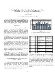
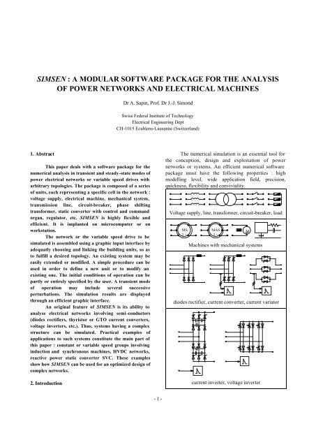
SIMSEN : A MODULAR SOFTWARE PACKAGE FOR THE ANALYSISOF POWER NETWORKS AND ELECTRICAL MACHINESDr A. Sapin, Prof. Dr J.-J. SimondSwiss Fe<strong>de</strong>ral Institute of TechnologyElectrical Engineering DeptCH-1015 Ecublens-Lausanne (Switzerland)1. AbstractThis paper <strong>de</strong>als with a software package for thenumerical analysis in transient and steady-state mo<strong>de</strong>s ofpower electrical networks or variable speed drives witharbitrary topologies. The package is composed of a seriesof units, each representing a specific cell in the network :voltage supply, electrical machine, mechanical system,transmission line, circuit-breaker, phase shiftingtransformer, static converter with control and commandorgan, regulator, etc. SIMSEN is highly flexible an<strong>de</strong>fficient. It is implanted on microcomputer or onworkstation.The network or the variable speed drive to besimulated is assembled using a graphic input interface bya<strong>de</strong>quatly choosing and linking the building units, so asto fulfill a <strong>de</strong>sired topology. An existing system may beeasily exten<strong>de</strong>d or modified. A simple procedure can beused in or<strong>de</strong>r to <strong>de</strong>fine a new unit or to modify anexisting one. The initial conditions of operation can bepartly or entirely specified by the user. A transient mo<strong>de</strong>of operation may inclu<strong>de</strong> several successiveperturbations. The simulation results are displayedthrough an efficient graphic interface.An original feature of SIMSEN is its ability toanalyse electrical networks involving semi-conductors(dio<strong>de</strong>s rectifiers, thyristor or GTO current converters,voltage inverters, etc.). Thus, systems having a complexstructure can be simulated. Practical examples ofapplications to such systems constitute the main part ofthis paper : constant or variable speed groups involvinginduction and synchronous machines, HVDC networks,reactive power static converter SVC. These examplesshow how SIMSEN can be used for an optimized <strong>de</strong>sign ofcomplex networks.2. IntroductionThe numerical simulation is an essential tool forthe conception, <strong>de</strong>sign and exploitation of powernetworks or systems. An efficient numerical softwarepackage must have the following properties : highmo<strong>de</strong>lling level, wi<strong>de</strong> application field, precision,quickness, flexibility and conviviality.Voltage supply, line, transformer, circuit-breaker, loadMS3 ~MAS3 ~<strong>Machines</strong> with mechanical systemsdio<strong>de</strong>s rectifier, current converter, current variatorcurrent inverter, voltage inverterM- 1 -
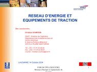
this machine are tuned by the regulators RU1 and RN1.The stator of this machine is connected to a HVDCtransmission constituted by 4 current convertersCONV1 - CONV4 and 4 transformers T1 - T4 with phaseshifting Yy0 and Yd11. Both AC si<strong>de</strong>s of thetransmission are equipped with filters C1- C4 for theelimination of the 12 th and the 24 th harmonics. Thecapacitor effect of the DC line is taken into account h bythe con<strong>de</strong>nser CCC1. The DC transmission line is tunedT1T2RG1 RL2L1u-+g consC1C2T5u consg+CONV1RRi1-CONV2-+C5u DCRP1CCC1i DC- p cons-++RC6RCONV4RQ1CONV3RRi2C7C3C4T3T4T6VAR1uME1MS1GS3~RRN1n-+Rby 2 current regulators Ri1 and Ri2, a power regulatorRP1 and an extinguishing angle regulator RG1 for theinverters CONV1 and CONV2. At the inverters si<strong>de</strong>, thevoltage is tuned by a reactive power static converter. Itis constituted by 2 transformers T5 - T6, 3 filters C5 - C7for the elimination of the 5 th , 7 th , 11 th and 13 thu cons+-RU1n consharmonics and the production of reactivepower, a current variator VAR1 and areactive power regulator RQ1. All thesystem is connected to the AC network S1through the line L1. This example is anaca<strong>de</strong>mical one in or<strong>de</strong>r to show the abilityof SIMSEN to simulate complex networks.The aim of the study is to analyse thedynamic behaviour of the system after asud<strong>de</strong>n change of the power set valuep cons of the power regulator RP1. In thissimulation, the extinguishing angle setvalue of the regulator RG1 keep aconstant value of 30°. Figures 4 to 11show the results of the simulation. Allthese results are referred to the ratingvalues of the synchronous machine MS1.Therefore SIMSEN is a suitable tool forthe <strong>de</strong>termination of optimal regulatorsand filters parameters relative to a complexstructure as presented in figure 3.S1Fig.3 Power network studied in example 1 : HVDC transmissionwith reactive power static converter (SVC)Fig. 4 Power set value "pcons" of the power regulatorRP1 and power "pg" of the HVDC transmissionFig.5 Voltage "uDC" and current "iDC" in the DC linkof the HDVC transmission-3-
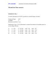
Fig. 6 Electromagnetic torque "tem" of thesynchronous machine MS1Fig. 9 Firing angle "α" of the current variator VAR1Fig. 7 Voltage set value "ucons" and voltage "umg" ofthe synchronous machine MS1Fig. 10 Reactive power "Q1" of the transformer T5(produced by the SVC)Fig. 8 Voltage set value "ucons" and voltage "uf" of thetransformer T5 (SVC)Example 2 : Static slip-energy recovery drive with induction machineand cyclo-converterFig. 11 Active power "P1" and reactive power "Q1" ofthe AC network S1- 4 -
S1T1L1Ri3RT2 T3 T4C5Ri2RC6C4- --RSU1Ri consMAS1RN1RC3MAS3~Pn mRi1RME1ME2n consC2C1is connected to the AC network S1 by 4transformers T1 - T4. The rotor phasecurrents are tuned by 3 current regulatorsRi1 - Ri3. The current set value of these 3regulators are given by the stator currentsregulator RSU1. The stategy of regulationis based on the voltage stator orientedmethod and <strong>de</strong>pends on the rotorposition. The aim of this method is toseparate the active and reactive statorcurrents. So, it is possible to guarantee ahigh power factor for this electrical drive.The speed of the machine is tuned by thespeed regulator RN1. The inductionmachine MAS1 drives the pump P.Figures 13 to 18 presents results ofa variation of the speed from 0.9 [p.u.] to1.1 [p.u.] with a constant mechanicaltorque of -0.5 [p.u.]. All the results aregiven in the rating values of the inductionmachine MAS1 : 80 MVA, 12.5 kV, 50 Hz, p= 6.Fig.12 Electrical drive studied in example 2 : Slip-energy recoverydrive with induction machine and cyclo-converterThe system studied is shown in figure 12. It consists of aninduction machine MAS1 with a rotor winding connected to a cycloconverterconstituted by 6 current converters C1 - C6. All the systemFig. 13 Electromagnetic torque "tem" and speed "nm"of the induction machine MAS1Fig. 15 Firing angle "α" of the current converter C1Fig. 14 Current set value "icons" and rotor phasecurrent "ig" of the induction machine MAS1Fig. 16 Current set value "idscons" and current "idsg"in the d axis of the induction machine (reactive power)- 5 -
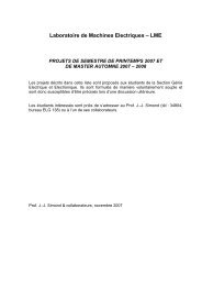
Fig. 17 Current set value "iqscons" and current "iqsg"in the q axis of the induction machine (active power)Fig. 18 Active power "P1" and reactive power "Q1" ofthe main transformer T1Example 3 :Shaft train torsional oscillations of largeturbo-generatorsMS1GS3~T1 L1 S1The system studied is shown in figure 20. Itconsists of 4 groups including : a synchronous machineMS, a mechanical shaft train ME, a voltage regulator RUand a transformer T. The 4 groups are connected to theAC network S1 through the line L1. A circuit-breaker D1allows to generate a three phase <strong>de</strong>fault on the highvoltage si<strong>de</strong> of each transformer. The main fieldsaturation in the d and q axis of the synchronousmachine have been taken into account as well as thecomplete shaft train (slip rings, large turbo-generatorand 4 turbines) of the mechanical system as representedin figure 19.R RU1-u consR RU2-u consME1MS2GS3~ME2MS3GS3~uuT2T3D1uu [p.u]Fd123456RRU3ME3Fq-i [p.u]SRGENLP3LP2LP1HPu consMS4GS3~T4Fig. 19 Saturation of the synchronous machine andshaft train for the mechanical systemRRU4ME4u-u consFig. 20 Power network studied in example 3 : Shafttrain torsional oscillations of large turbo-generatorsThe aim of the study is to analyse the dynamicbehaviour of the system with 1 or 4 machines after a onoffswitching of the circuit-breaker D1. The operatingpoint of the first turbo-generator MS1 is the same inboth cases. Figures 21 and 22 show the results of thetwo simulations. All the results are given in the ratingvalues : 1200 MVA, 28.5 kV, 50 Hz, p = 1.- 6 -
Fig. 21 Electromagnetic torque of the synchronousmachine MS1 ("tem" : 1 machine, "tem' " : 4 machines)[6] J.-J. Simond : "Nachbildung eines Systems ausSynchronmaschine, Frequenzumrichter und Drehstromnetzmit Simulation instationärer Vorgänge". ETZ Archiv, Bd.10, 1988.[7] A. Sapin, J.-J. Simond, B. Kawkabani : "Frequencyconverter-fed synchronous machines : Interactivesimulation system", ICEM 1992.[8] A. Sapin, J.-J. Simond, B. Kawkabani : "SIMSEN : amodular software package for the analysis of powernetworks and electrical machines", ICEM 94.[9] A. Sapin, J.-J. Simond : "SIMSEN : a modular softwarepackage for the analysis of power networks and variablespeed drives", EPE Lausanne, 1994.Fig. 22 Torsional torque between the generator andthe turbine ("tkθ" : 1 machine, "tkθ' " : 4 machines)5. ConclusionA modular software package for the analysis ofpower networks and electrical machines - SIMSEN - hasbeen <strong>de</strong>scribed. This package is a flexible, convivial an<strong>de</strong>volutive tool for the conception, <strong>de</strong>sign an<strong>de</strong>xploitation of complex power systems with an arbitrarytopology including also elements with semi-conductors.The field of applications of SIMSEN is very wi<strong>de</strong>, thenumerical simulation is possible un<strong>de</strong>r steady-state ortransient conditions. A possibility exists for the user tointroduce in a simple manner a new unit or to modify anexisting one.6. References[1] H. Bühler : "Convertisseurs statiques". Pressespolytechniques roman<strong>de</strong>s, Lausanne 1991.[2] H. Bühler : "Electronique <strong>de</strong> réglage et <strong>de</strong> comman<strong>de</strong>".Traité d'Electricité, vol XVI, 1 ère édition, Pressespolytechniques roman<strong>de</strong>s, Lausanne 1982.[3] I. M. Canay : "Exten<strong>de</strong>d synchronous machine mo<strong>de</strong>l forthe calculation of transient processes and stability", Electr.Mach. a. Electromech. No 2, pp 137-150, 1977.[4] EMTP Rule book. Bonneville Power Administration.Portland Oregon[5] EUROSTAG, Software for the Simulation of PowerSystems Dynamics. Electricité <strong>de</strong> France, Tractebel 1990.- 7 -