simsen - Laboratoire de Machines Electriques (LME)
simsen - Laboratoire de Machines Electriques (LME)
simsen - Laboratoire de Machines Electriques (LME)

You also want an ePaper? Increase the reach of your titles
YUMPU automatically turns print PDFs into web optimized ePapers that Google loves.
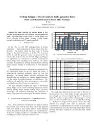
S1T1L1Ri3RT2 T3 T4C5Ri2RC6C4- --RSU1Ri consMAS1RN1RC3MAS3~Pn mRi1RME1ME2n consC2C1is connected to the AC network S1 by 4transformers T1 - T4. The rotor phasecurrents are tuned by 3 current regulatorsRi1 - Ri3. The current set value of these 3regulators are given by the stator currentsregulator RSU1. The stategy of regulationis based on the voltage stator orientedmethod and <strong>de</strong>pends on the rotorposition. The aim of this method is toseparate the active and reactive statorcurrents. So, it is possible to guarantee ahigh power factor for this electrical drive.The speed of the machine is tuned by thespeed regulator RN1. The inductionmachine MAS1 drives the pump P.Figures 13 to 18 presents results ofa variation of the speed from 0.9 [p.u.] to1.1 [p.u.] with a constant mechanicaltorque of -0.5 [p.u.]. All the results aregiven in the rating values of the inductionmachine MAS1 : 80 MVA, 12.5 kV, 50 Hz, p= 6.Fig.12 Electrical drive studied in example 2 : Slip-energy recoverydrive with induction machine and cyclo-converterThe system studied is shown in figure 12. It consists of aninduction machine MAS1 with a rotor winding connected to a cycloconverterconstituted by 6 current converters C1 - C6. All the systemFig. 13 Electromagnetic torque "tem" and speed "nm"of the induction machine MAS1Fig. 15 Firing angle "α" of the current converter C1Fig. 14 Current set value "icons" and rotor phasecurrent "ig" of the induction machine MAS1Fig. 16 Current set value "idscons" and current "idsg"in the d axis of the induction machine (reactive power)- 5 -