QM-Data200 and Vision Unit - Mitutoyo Scandinavia AB
QM-Data200 and Vision Unit - Mitutoyo Scandinavia AB
QM-Data200 and Vision Unit - Mitutoyo Scandinavia AB

You also want an ePaper? Increase the reach of your titles
YUMPU automatically turns print PDFs into web optimized ePapers that Google loves.
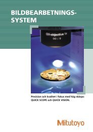
Functions for Faster! Easier!<strong>and</strong> More Efficient Measurement!<strong>QM</strong>-<strong>Data200</strong>AI MEASUREMENT FUNCTIONWith the AI measurement function (Automatic Element-Identification function), elementscan be automatically identified based on data input from the measuring points. Thisfunction allows the continuous measurement of different elements, eliminating key entry foreach element.Elements that can be identified using the AI functionIn the following, one of the two has to be selected: [Line <strong>and</strong> distance][Ellipse <strong>and</strong> rectangular hole] [Ellipse <strong>and</strong> slotted hole]Continuous measurement of insidediameter (A) <strong>and</strong> angle (B)21A312B34PointLineCircleDistanceEllipseRectangularholeSlotted hole Intersection1. Select the [AIMEASUREMENT] key.Note) The most recent measurementresult is displayed.2. Input data from the threemeasuring points of insidediameter (A).3. End the measurement.(Press F5)7. The measurement result of theangle is displayed.6. End the measurement. (Press F5)5. Input data from the fourmeasuring points of angle (B)The coordinate entry functionIn a measurement using the coordinate entry format, the coordinates calculated from themeasurement data (coordinates of the center of a circle, etc.) are applied to data entry asone measuring point. For example, measurement of the pitch of a rectangular hole can beexecuted simply by selecting the [PITCH MEASUREMENT] key <strong>and</strong> the [RECTANGULAR HOLECENTER] in the coordinate entry format.2. Press [COORDINATEENTRY FORMAT].1. Press [CIRCLE EASUREMENT]to measure circle C4.Measurement of a pitch circlewhose circumference intersectswith the three hole centersC1Circle C44. The measurement result of theinside diameter is displayed.Types of coordinate entryformatsDirectly entered pointsUse the point that has been entered as a measuring pointMidpoint between the twoUse the midpoint between the two points as a measuringpoint.Center of circle (three points)Use the center of the circle whose 3 points have beenentered, as a measuring point.Center of circle (four points)Use the center of the circle whose 4 points have beenentered, as a measuring point.Measurement status of pitchcircle display unitC2C3Center of ellipseUse the center of the ellipse as a measuring point.3. Measure circle C1 (entry of four points).Likewise, measure circles C2 <strong>and</strong> C3.4. Select the center of each circle(entry of four points).Coordinate entry formatdisplay unit5. The diameterof a pitchcircle (C4)can befound.Center of rectangular holeUse the center of the rectangular hole as a measuringpoint.Center of slotted holeUse the center of the slotted hole as a measuring point.Intersection of two straight linesUse the intersection of the two straight lines as ameasuring point.5
A variety of measurement comm<strong>and</strong>sfor all the basic measurements.Basic element measurement keyPointCoordinates (The multi-point processing allows dataprocessing of up to 100 measuring points)*In the multi-point processing, mean value is used as measured value.Point-point distanceDistance, Coordinates differenceLineAngle <strong>and</strong> perpendicularity with the X-axis. (Multipointprocessing for a maximum of 100 points)EllipseCenter coordinates, diameter along the major axis,diameter along the minor axis, angle with the X-axis,Departure from the X-axis (Multi-point processing fora maximum of 100 points)CircleCenter coordinates, diameter, roundness(Multi-point processing for a maximum of100 points)Rectangular holeCenter coordinates, length, widthSlotted holeCenter coordinates, length, width, radius of slottedholeCreating the coordinate systemDetermining axis by pointRotate the X-axis coordinate in such a way that itpasses through the measuring point. (Do not translatethe origin.) The rotation angle can be entered directly.Coordinate system pattern 4The measuring point is the origin, <strong>and</strong> the line thatpasses through another measuring point is the X-axis.Coordinate system pattern 1The line that passes the measuring point is the X-axis,<strong>and</strong> the line that passes through another measuringpoint <strong>and</strong> intersects the X-axis making a 90-degreeangle is the Y-axis.Pattern measurement keyPitchPoint-point distance, differencebetween coordinates, angle, cumulativedistance, cumulative angleLine-circle intersectionCoordinates of intersectionLine-point distanceVertical distanceIntersection of circlesCoordinates of intersectionIntersection point <strong>and</strong> intersecting angleIntersection coordinates, intersecting angle,supplementary angleCompensation of offset axisRotate the coordinate system until the measuringpoint comes to the specified position. (Do nottransfer the origin.)Origin settingTranslate the coordinates horizontally until themeasuring point is positioned as the origin. Thedisplacement value can be entered directly.Coordinate system pattern 2The line that passes through the measuring point isthe X-axis, <strong>and</strong> its midpoint is the origin.Line-circle distanceCenter-center distance, longestdistance, shortest distanceMidpoint between pointsCoordinates of midpointThe item described here as the measurement resultoutput is the factory setting.Saving, recalling, <strong>and</strong> resetting thecoordinate systemSaving, recalling, <strong>and</strong> resetting thecoordinate systemDetermining axis by lineRotate the coordinate system in such a waythat it becomes parallel to the measuredline. (Do not translate the origin.)Coordinate system pattern 3The line that passes through the measuringpoint is the X-axis, <strong>and</strong> the intersection withanother line is the origin.Circle-circle distanceCenter-center distance, longestdistance, shortest distance,difference between coordinatesMidpoint between line<strong>and</strong> pointCoordinates of midpointCenter line between linesAngle with the X-axisPerpendicularityPerpendicularityParallelismOTHERKey menuHeightHeight (distance between steps inthe Z-axis direction)Point-circle tangent pointCoordinates of tangent pointCircle-circle tangent lineAngle with the X-axisCornerDiameter, radius of cornercircle, center coordinatesCircle-point distanceCenter-center distance, longestdistance, shortest distance,difference between coordinatesOptional accessoriesAdjustable StageOrder No. 172-270• The maximum loadingcapacity is 60kg.Midpoint between circlesCoordinates of midpointReceipt printerOrder No. 12AAD032Projected pointCoordinates of the pointprojected on a lineThe item described here as themeasurement result output is the factorysetting.USB-FDD <strong>Unit</strong>Order No. 12AAH035Printing method Thermal serial dot• Used to print out measurement Printing digits 40 digitsresults.Maximum print speed 52.5cps (normal characters)Optional AccessoriesDimensions (XxDxH) 160mmx170mmx65.5mm(printer body)Order No.908353 Recording paper for receiptprinter (5 rolls/set)St<strong>and</strong>ard accessories Printer cable, recording paper(1 roll), AC adapter (100V)*Supports external printer (color or black & white) for ESP/CPrinter control code system: ESC/P, MS-DOS 24 pinsPrinter cable 2m (12AAA804)… optionalUSB-Memory stickOrder No. 12AAH034• It is used to save measurementprocedures <strong>and</strong> measurement result files.8
<strong>QM</strong>-<strong>Data200</strong>SYSTEM CONFIGURATIONMain unit with SPC outputPJ-A3000 seriesPJ-H3000 series, PJ-500PH-3515F (172-847)MUX-10F264-002Direct connectionSPC cable936937 (1m) x2pcs.Main unit with RS-2322C outputPJ-A3000D/F seriesMF-A seriesMF-U series, PJ-H seriesRS-232C cable(2m)12AAA807DMX-212AAD538Connectingcable D12AAD195Connectingcable C12AAD194For RS-232C input (Connected tothe measuring instrument counter)KS Counter (PV)OPTOEYE A2 CounterMain unit with built-in OptoeyePJ-H3000F4 seriesConnecting cable B12AAD193Connecting cable E12AAD196PowerswitchFor USB-FDD unit orUSB-Memory connectionFor printerconnectionFor OPTOEYE sedge signal inputFor RS-232C output(Connected to PC)<strong>QM</strong>-<strong>Data200</strong> SpecificationsFor linear scale inputFor footswitch inputOrder No. St<strong>and</strong>-mount type 264-145*/264-149(only for Hyper MF/MF-U) Arm-mount type 264-146*Display languages (selectable)Japanese/English/German/French/Italian/Spanish/Portuguese/Czech/Chinese/KoreanMeasured value unitmm Angle: degree/degree minute second (selectable)Resolution0.0001mmProgram functionsPart program creation, execution, editing.Statistical processingNumber of data, maximum value, minimum value, mean value, st<strong>and</strong>ard deviation, range, histogramNumber of elements that canbe stored in the memoryMaximum of 1000 elementsElement recallPoint, line, circle, distance, ellipse, rectangular hole, slotted hole, intersection <strong>and</strong> intersecting angleElement key-inpoint, line, circleDisplay systemMonographic LCD (320x240 dots, with back light)RS-232C 2: For connecting the measuring instrument’s counter X, Y, Z: Linear scale input (for the no-counter type)Input connectorOPTOEYE: Optoeye edge signal (for connecting OPTOEYE M2)Note: Available only with linear scale input FS: For connecting the footswitchRS-232C 1: For connecting PC (measurement result)Output connectorPRINTER: For connecting a receipt printer or an external printer (measurement result)FD: For connecting the floppy disk drive unit (measurement result file, measurement procedure file)Measurement result file outputRS-232C output (CSV format, MUX-10 format)PowerAC adapter (Input: 100V-240V, output: 12V DC)Maximum power consumption24W (does not include optional accessories)Outer dimensions (WxDxH) 260x242x310mm (including the st<strong>and</strong>) 318x153x2751mm (when the arm is in the horizontal posture)Mass Approximately 2.2 kg Approximately 2.1kgApplicable modelsPJ/PJ-H series, PJ-A3000 series (except the fixed-stage type)PJ-A3000 series (except the fixed-stage type),PH-3515F (172-847)PV-5000, PH-3515F (172-949)St<strong>and</strong>ard accessoriesAC adapter, power cableTo denote your AC line voltage add the following suffixes (e.g. 264-140A) A for 120V, C for 110V, D for 220V, E for 270V. No suffix is required for 100V*9
VISION UNITFEATURES> Your measuring microscope will be upgraded to avision measuring machine with the use of the <strong>QM</strong>-<strong>Data200</strong>.> The automatic edge-detection tools <strong>and</strong> variousmacro icons allow measurement in one easy step.> The graphics <strong>and</strong> measurement navigationfunctions facilitate operation.> Image data input/storage function.> Measurement results are output to MS-Excel®*.This lets the user generate an inspection table onthe same computer.> Allows the tolerance zone measurement ofmeasurement results <strong>and</strong> various types of statisticalprocessing for each item.> Combined use with the focus pilot provideshigh-accuracy in height measurements. (patentpending)> A series of measuring operation can be performedusing just one screen display.> The auto-brightness control function faithfullyreproduces the type <strong>and</strong> degree of illuminationused. (This function is limited to the MF/MF-Useries.)*MS-Excel® is a registered trademark of Microsoft Corporation.See the instantaneous measurement using a <strong>Vision</strong> <strong>Unit</strong>!There is no need to look into the eyepiece of the measuring microscope simply to align the cross-hairs on the testpiece. The electronic eye of the CCD camera captures the edge using the automatic detection. If the measuringpoint is within the video window screen, the measurement <strong>and</strong> calculation will be completed instantly. This reduceshuman errors, prevents eye fatigue, <strong>and</strong> improves repeatability, thus greatly reducing the measuring time.Measuringthe inside diameter1. Capture the inside diameter of the test piece to be measured onthe video window, then adjust the brightness <strong>and</strong> focus with themeasuring microscope’s main unit.2. Select the “Circle Measurement” key from the functionwindow, <strong>and</strong> “One-click Circle Tool” for edge detection fromthe tool window.10
Smart EditorDuring a part program list display,the target position of XY stagetravel, coordinate system creation,measuring item comm<strong>and</strong>, <strong>and</strong>edge detection tool are displayedindependently as icons or on labels,to facilitate part program editing.Icon EditorUsing the Icon Editor, thelayout of icons such as themeasurement key icon,tool icon, etc., can be freelyarranged. The layout settingcan be freely determined.Auto-brightness control function (exclusive to MF/MF-U series)The light volumes of microscope’s transmitted <strong>and</strong> reflected lightscan be controlled via the software on the PC. It is not necessaryto adjust the illumination during a repeat measurement, since theillumination is faithfully reproduced according to the setting selectedduring the creation of the part program. Even in the measurementof a test piece that requires variations in illumination, consistentlyaccurate edge detection is ensured. This enhances the efficiency ofrepeated measurements.[MF series brightness control switch panel] [MF-U series brightness control switch panel]With the MF series, this function isavailable even when the optionalring fiber illuminator, an externalillumination system, is connected.Contrast levelThe contrast around the center of the video window is indicated by alevel meter. The peak that is indicated on the level meter is the focalpoint. This will improve the focal point reproducibility of a manual-typemeasuring microscope.Video image scale displayThe scale display, which is proportionate to the real field ofview, on the video window lets the operator quickly grasp theapproximate size of a test piece. The image can be saved alongwith the scale display.12
SYSTEM CONFIGURATIONCCDcameraSt<strong>and</strong>ard component0.5xTVAdapterFocusPilot* 2C-mount* 1Adapter BFoot switch<strong>Mitutoyo</strong>measuring microscopesMF/MF-U series<strong>Mitutoyo</strong>measuring microscopesTM321/322/331 series,MF* 3 /MF-U seriesMeasuring microscopemade by other manufacturersNikon, Olympus, or Topcon digital scale<strong>and</strong> measuring microscope with TV port.Software: QS PAK ®(For <strong>Vision</strong> <strong>Unit</strong>)Brightnesscontrol switchpanel(rear panel)Counter cableCounteror RS-232COutput unit* 1 RS-232C Cable* 1RS-232C cableCommon optional accessoriesExternal lightcontrol cable(For the MF series only)Ring fiberIllumination system(For the MF series only)Laserprinter* 1 Not included in the <strong>Vision</strong> <strong>Unit</strong>. Differs according to the specifications of the measuring microscope.* 2 The focus pilot ® is a focal-point detection unit allowing highly accurate <strong>and</strong> ghighly reproducible focal-point detection.* 3 Supports only the microscope unit with the built-in image forming lens with a magnification of 1X. Check the specifications of the micrscope unit.Calibration chartSpecial table14
SpecificationsVISION UNITMeasuring unitWith <strong>Mitutoyo</strong> microscope: 0.5X (0.5X built-in TV adapter)Optical systemWith other maker’s microscope: 1X (CCD camera directly attached)Image detection system high-sensitivity 1/3” CCD color cameraCCD camera outer dimensions 100(W)x58(D)x92(H) mmMass of CCD camera 0.4 kgMonitor magnification/imageWith <strong>Mitutoyo</strong> microscope: approximately 63X /3.1x2.3 mmrangeWith other maker’s microscope: approximately 126X /1.57x1.17mm(With use of objective lens 3x)Resolution0.0001mmAxial length measuringaccuracy* 1Depending on the accuracy of the measuring microscope(Measuring condition 20°C)Repeatability* 2(Measuring condition 20°C)* 1 “Measuring accuracy” means a difference between an actual measured value in a vision measurement <strong>and</strong> a true value.* 2 “Repeatability within a screen” means the dispersion of measured values when different positions within the same screen aremeasured repeatedly.Data processorCPUCRT displayOSSoftwareMaximum powerconsumptionPentium 3 or upper /128MB or more17 inch/SVGA colorMS-Windows XP*QSPAK Ver6.0 or more460WTM321/322/331, MF/MF-U series (Not compatible with MF-U)Applicable models *Digital scale made by Nikon, Olympus, or Topcon (Equipped withcounter with RS-232C output) <strong>and</strong> Measuring microscope with TV port(An optional accessory provided by the maker, such as C-mount or RS-232C cable is needed.)*MS-Windows XP is registered trademarks of Microsoft Corporation of the U.S.A.Depending on the accuracy of the measuring microscopeRef.: Repeatability of 1 screen (<strong>Mitutoyo</strong>’s st<strong>and</strong>ard sample is used)3X objective lens is used: 3σ=±2.5µm or less10X objective lens is used: 3σ=±1.0µm or lessDimensions212.5 (8.37")91.5 (3.60")Order No.359-670 (for MF)359-675 (for Mf-U)100 (3.94") 58 (2.28")32 (1.26")ø45 (1.77")<strong>Unit</strong>: mm (inch)0.5XAdapter unitOptional softwareFORMPAK-QVFORMPAK-QV allows contour analysis <strong>and</strong> contourtolerancing against the nominal value, from the dataacquired using QSPAK.• Contour tolerancing function• Fine contour analysis function• Report generation functionCAD Import & ExportOperability has been greatly improved, <strong>and</strong> the timerequired to create a part program has been greatlyreduced, by importing the CAD data (DXF, IGES), asgenerated in the product-design stage, to QSPAK. Themeasurement result from the QSPAKcan be converted to CAD data.Contour tolerancing screenFine contour analysis screenFeatures> The nominal value of eachmeasuring item is enteredautomatically.> The graphics windowcan be used to calculateelements.> Graphics data can beoutput in a specified CADdata format.15
32.60 0702 4 E (PA) NE, Printed in JapanSc<strong>and</strong>inavia <strong>AB</strong>Släntv. 6 • Box 712SE-194 27 Uppl<strong>and</strong>s VäsbyTel: 08-594 109 50Fax: 08-590 924 10info@mitutoyo.sese