PRINCIPLES AND PARAMETERS - Pinewood Studios
PRINCIPLES AND PARAMETERS - Pinewood Studios
PRINCIPLES AND PARAMETERS - Pinewood Studios

Create successful ePaper yourself
Turn your PDF publications into a flip-book with our unique Google optimized e-Paper software.
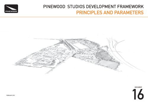
PINEWOOD STUDIOS DEVELOPMENT FRAMEWORK<strong>PRINCIPLES</strong> <strong>AND</strong> <strong>PARAMETERS</strong>FEBRUARY 2013DOCUMENT16
2 <strong>Pinewood</strong> <strong>Studios</strong> Development Framework | <strong>PRINCIPLES</strong> <strong>AND</strong> <strong>PARAMETERS</strong>
<strong>Pinewood</strong> <strong>Studios</strong> Development Framework | <strong>PRINCIPLES</strong> <strong>AND</strong> <strong>PARAMETERS</strong>3ContentsProduced on behalf of <strong>Pinewood</strong> <strong>Studios</strong> Ltd by:Arup Associates - Masterplanners and Sustainability ConsultantsArup - Infrastructure and Environmental ConsultantsRandall Thorp - Landscape ConsultantsVectos - Transport ConsultantsTurley Associates - Planning ConsultantsCBRE - Development Consultants01Introduction02Development Proposed03Development Principles04Parameters05Explanation of ParametersArup Associates8 Fitzroy StreetLondonW1T 4BJUnited KingdomT +44 (0)20 775 55555www.arupassociates.comwww.arup.com
4 <strong>Pinewood</strong> <strong>Studios</strong> Development Framework | <strong>PRINCIPLES</strong> <strong>AND</strong> <strong>PARAMETERS</strong>01 INTRODUCTIONT his document is the principal design document for approval as partof the <strong>Pinewood</strong> <strong>Studios</strong> Development Framework outline planningapplication. It contains baseline and parameter drawings followingan explanation of the defining set of principles that have informed theframework design.It comprises a set of written development principles and a series ofparameter plans for site layout, landscaping and ecology measures,building massing and gross external floor areas and access andcirculation. Together, these provide the framework within which moredetailed ‘reserved matters’ applications will be prepared in the future.An explanation of how the Parameter drawings are to be interpretedand applied is also provided.This document creates a flexible and adaptable approach to the futuredevelopment of the site, within clearly defined parameters, includingan anatomy of open space, access and movement, and massingand a set of written development principles. These Principles andParameters focus on the definition of open space, landscape, anddevelopment areas, and on the treatment and character of boundariesand different areas within the overall development. The primaryroad and access routes are established to ensure the site evolveswith a clear anatomy that endures as the phases of development areimplemented over time.The precise design scale and siting of each building and its individualappearance is left illustrative at this stage, allowing for future designdevelopment and evolution as the project is implemented over time.The parameters form the basis of the scheme assessed in theDFPrinciples and ParametersFOR APPROVALEnvironmental Statement.D&ADesign and Access StatementSUPPORTING INFORMATIONIMIllustrative MasterplanNOT FOR APPROVAL
<strong>Pinewood</strong> <strong>Studios</strong> Development Framework | <strong>PRINCIPLES</strong> <strong>AND</strong> <strong>PARAMETERS</strong>025Development Proposed
6 <strong>Pinewood</strong> <strong>Studios</strong> Development Framework | <strong>PRINCIPLES</strong> <strong>AND</strong> <strong>PARAMETERS</strong>02 THE DESCRIPTION OF DEVELOPMENT“Reconfiguration and expansion of facilities for screen based media, including film, television and video games, andassociated services and industries, comprising: demolition of existing outdated accommodation; erection of new stages,workshops, office accommodation, demountable modular buildings, entrance structures and reception and security offices,gas CHP energy centre, underground waste water treatment plant, recycling facilities, backlots and film streetscapes;external film production; creation of a new vehicular and pedestrian access from <strong>Pinewood</strong> Road, emergency accessfrom Sevenhills Road, access roads within the site, surface and multi-level car parking; and associated landscaping andecological habitat creation works.”Within this description of development formal approval is being sought for a mix of detail and outline elements.Detailed approval is sought for:• description of development• overall schedule of accommodation• vehicular access from the public highwayOutline approval is sought for:• guiding Development Principles• controlling Parameters:- use and quantum- development zones- green space- landscaping and ecology- movement- building scale and massing
<strong>Pinewood</strong> <strong>Studios</strong> Development Framework | <strong>PRINCIPLES</strong> <strong>AND</strong> <strong>PARAMETERS</strong>037Development Principles
8 <strong>Pinewood</strong> <strong>Studios</strong> Development Framework | <strong>PRINCIPLES</strong> <strong>AND</strong> <strong>PARAMETERS</strong>03 DEVELOPMENT <strong>PRINCIPLES</strong>Capturing growth in theinternational film industryThere are high order strategic guiding principles which have beeninfluential in the development of the design solution for PSDF.1. Meeting globally-arising market needs at <strong>Pinewood</strong> within theWest London strategic film and media cluster in support of the key growthambition of the UK film industry and economy.The development principles are set out below in support of theapplication; some will be suitable for inclusion as conditions in anyplanning permission.This is the fundamental commercial/economic driver for the <strong>Pinewood</strong><strong>Studios</strong> scheme and is the basis of the economic case for the PSDF.The market and commercial case is analysed in the applicationdocuments which demonstrate insufficient current capacity in the UKto capture international growth and inward investment.Raising production capability2. Increasing film, TV and other screen based media productioncapability at the <strong>Pinewood</strong> <strong>Studios</strong> site.The capability principle is driven by the need for more studio space inthe UK and the requirements of film producers for larger, more flexiblestudio facilities located alongside all the production/creative/technicalresources that are required on hand.Capability therefore includes detailed consideration of overallcapacity, range and flexibility of production buildings and spaces,ancillary accommodation and support services including technologicalprovision. The PSDF seeks to resolve all of these requirements in itsdesign process and outcome.
<strong>Pinewood</strong> <strong>Studios</strong> Development Framework | <strong>PRINCIPLES</strong> <strong>AND</strong> <strong>PARAMETERS</strong>9Achieving sustainable developmentLandscape-led3. Creating a genuinely sustainable development by design.Achieving sustainable development is a key policy requirement of theNational Planning Policy Framework and a leading influence on thedesign process and outcome.Sustainability is to be achieved in two related ways:- technical sustainability of design and mitigation- strategic sustainability by balancing of economic, social andenvironmental considerations.Both exercises are carried out in the application documents.Optimising the use of existing<strong>Pinewood</strong> estate4. Making best use of non-Green Belt and previously developed landbefore use of Green Belt land.5. Adopting a landscape-led design process that is integrated into thedevelopment.The application site is in part undeveloped open land with a range ofnatural landscape features. The design process is intended to setthe proposed development within a structural landscaped context tominimise any adverse effects.Ecological enhancements6. The ecological value and biodiversity of the site to be subject toa principle of minimal disruption and the promotion of measures forenhancement.The application site has a significant ecological asset value which willbe affected by any development. The guiding principle is to maintainand enhance the best of the asset and mitigate impacts through anecological strategy.The most effective and efficient use of the existing <strong>Pinewood</strong> <strong>Studios</strong>site to meet development requirements is a guiding principle subjectto achieving an acceptable overall operating environment.
10 <strong>Pinewood</strong> <strong>Studios</strong> Development Framework | <strong>PRINCIPLES</strong> <strong>AND</strong> <strong>PARAMETERS</strong>03 DEVELOPMENT <strong>PRINCIPLES</strong>Protecting local amenity7. The development process and outcome maintain and wherepossible enhance the amenity of neighbouring users/uses.The application site is adjoined by a mix of residential, CountryPark and agricultural land neighbouring uses. The principle is todemonstrate a solution that respects the amenity of neighbours interms of activity and appearance.Dedicated use for film/mediaproduction8. The <strong>Pinewood</strong> <strong>Studios</strong> expansion is for the purpose ofimprovement of the film, TV and screen based media hub as a singleintegrated facility.The development has a particular and exceptional justification thatshould be reflected in its design, development and operation.
<strong>Pinewood</strong> <strong>Studios</strong> Development Framework | <strong>PRINCIPLES</strong> <strong>AND</strong> <strong>PARAMETERS</strong>0411Parameters
12 <strong>Pinewood</strong> <strong>Studios</strong> Development Framework | <strong>PRINCIPLES</strong> <strong>AND</strong> <strong>PARAMETERS</strong>04 <strong>PARAMETERS</strong>The Parameters are defined in a set of drawings contained within thisdocument• Use and Quantum (Plans P-P-003, P-P-004 and P-P-007)• Development Zones and Levels (P-P-003)• Green Space (P-P-001)• Landscaping and Ecology (P-P-002)• Site Access and Circulation (P-P-005)• Building Scale and Massing (P-P-006 and P-P-007)What are Development Parameters?The development parameters establish a framework for the futureredevelopment of the site. Amongst other things they establish theareas of the site that may be built on, and the areas that will belandscaped. Maximum/minimum footprints and heights for all buildingtypes are defined as are the locations of primary and secondary accessroads, subject to limited levels of deviation.In the future more detailed “reserved matters” applications willbe prepared. These applications will be required to demonstratecompliance with the parameters defined in this document.
<strong>Pinewood</strong> <strong>Studios</strong> Development Framework | <strong>PRINCIPLES</strong> <strong>AND</strong> <strong>PARAMETERS</strong>13The baseline, application, and parameter drawings for approval follow.All other drawings fall separately under the design and access statement,illustrative masterplan document and other supporting documentation notintended for approval.Drawings for Approval category titleBaseline DrawingsP-B-000P-B-001P-B-002Application Site BoundaryExisting Site PlanBaseline PlanPSDF List of Drawings forApprovalApplication DrawingsP-A-001Proposed DemolitionsP-A-002-1 Tree Removal Plan, Sheet 1P-A-002-2 Tree Removal Plan, Sheet 2P-A-002-3 Tree Removal Plan, Sheet 3P-A-003Site Access, <strong>Pinewood</strong> Road Main Entrance PlanP-A-004Site Access, Seven hills Road, Emergency Access PlanParameter DrawingsP-P-001P-P-002P-P-003P-P-004P-P-005P-P-006P-P-007Green SpaceLandscape and EcologyDevelopment Zones and LevelsAreas by Development ZoneSite Access and CirculationBuilding PlotsAreas and Dimensions by PlotBaseline Drawings110125-A-28110125-B-38Site Location PlanSite Location PlanFPR List of Drawings forApproval110125-A-27110125-B-26Extents of Works PlanHighway Improvement Scheme
Notes:KEY:EXTENT OF WORKSEXISTING PUBLIC HIGHWAY BOUNDARYEXISTING SPEED GATE <strong>AND</strong>ILLUMINATED SIGN WITH NEWROUNDEL TO BE RELOCATED TOTHIS POSITION.EXISTING SPEED REDUCTIONROAD MARKINGS <strong>AND</strong>SIGNAGE. TO BE RELOCATEDAS SHOWN.REV. DETAILS DRAWN CHECKED DATECLIENT:EXISTING SPEED GATE TO BERELOCATED TO THIS POSITIONWITH NEW ROUNDEL.CROSSINGLINKS TOFOOTPATHSWITHIN EASTAREA.PROJECT:L<strong>AND</strong>SCAPE PROPOSALSNOT SHOWN. L<strong>AND</strong>SCAPING<strong>AND</strong> FOLIAGE REMOVEDWILL BE DESIGNED TOPROVIDE SUFFICIENTVISIBILITY TO ROUNDABOUT<strong>AND</strong> TOUCAN CROSSING.NEW SIGNALISEDPEDESTRIAN /CYCLIST CROSSING(TOUCAN)CROSSINGLINKS TOFOOTPATHSWITHIN WESTAREA.DRAWING TITLE:SCALES:DRAWN:CHECKED:DATE:DRAWING NUMBER:P-A-003REVISION:D
Notes:CROSSOVER TO BE CONSTRUCTED OFTARMACADAM OR SIMILAR LOCALAUTHORITY APPROVED MATERIAL (tbc).KEY:EXTENT OF WORKSEXISTING PUBLICHIGHWAY BOUNDARYSIGN TO BEMOUNTED ONNEW GATEEXISTING ACCESSTO BE WIDENED.2 No. TREES TOBE REMOVEDR8.00REV. DETAILS DRAWN CHECKED DATECLIENT:PROJECT:R15.00DRAWING TITLE:EMERGENCY ACCESSROUTE ON PSL L<strong>AND</strong> TOBE CONSTRUCTED USING'GRASSROAD' OR SIMILARAPPROVED SURFACINGMATERIAL (tbc).EXISTING GATE TOBE REMOVED <strong>AND</strong>REPLACED WITHNEW GATE.SCALES:DRAWN:CHECKED:DATE:DRAWING NUMBER:P-A-004REVISION:D
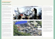
A1A B C D E F G H I J K L M NLodge12Langley Woodhouse34St BenedictTennisCourtPresbyteryThe BridgettineConventAstraeaLarkswoodPine CottageParkspringLodgePantilesThe FirsWoodcroftPostsWoodCottageDickTurpinsCottageSpringfield CottagesHollydeneLB70.4m70.1mMastHill ViewHome FarmGantryCherryOrchardFarmCherry OrchardFarm BungalowPondBlanchard's Farm55.6mBelleFarmLodgeBelle FarmCottageNursery57.3mThe OaksNPondPondDedicated Cycle path Centreline LOD +/- 30 metresLong CoppiceSevenhills FarmWeirPlanning Application BoundaryLandscapeDevelopment CellsLimits of DeviationEdge of Land Use +2/-10 mts.Edge of Land Use +5 /-10 mts.G:\Jobs\224788-10 PSB - ARAS\4-03 Drawings\4-03-01-02 Arch\Planning\P-P-001.dwg 23 Jan 2013 15:22:41 id: 82F58B19-EF6E-498A-B2D8-82E49F91CFE4 Amparo.GalvanGantryDromenagh5FarmStrawberry WoodPondDromenaghFarm House60 XXXXXX / /Issued for Outline Planning ApprovalPondIssueDate7Black ParkPondsKnoll HouseHeathwoodArup AssociatesPondBrattonCattle Grid<strong>Pinewood</strong>Mews13 Fitzroy Street London W1T 4BQ United Kingdomt +44 20 7755 2525www.arupassociates.comKey Plan8TCBIssuesBaney9LBChardanHouseAlburyHouseLaurel CourtClient<strong>Pinewood</strong> <strong>Studios</strong> Ltd.Job Title<strong>Pinewood</strong> <strong>Studios</strong>Development FrameworkSpring1060.6mDrawing TitleGreen SpacePondPark Lodge FarmGamekeepersCottageIssuesFB49.1mScale at A11:2500DisciplineMasterplanning11010m50m100m250mIver HeathBrackenwoodPondLBMapping reproduced by permission of Ordnance Survey onbehalf of HMSO. © Crown copyright and database right 2012.All rights reserved.Ordnance Survey Licence number 100018033Stag andJob No224788-00Drawing NoP-P-001Drawing StatusPLANNINGIssue0hHoundsDellfield FarmDo not scale(PH)© Arup Associates
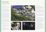
A11234A B C D E F G H I J K L M N+5.0m+5.0mRETAINEDTrees, hedges, shrubsretained with improved managementGrassland retained with improvedmanagementOpen waterDitchesArea retained as private gardenPROPOSALS(subject to detailed LandscapeDesign)Species rich grassland and heathOpen waterWoodlandSpecies rich scrubDamp grassland / marshScattered tree plantingSpecies rich scrub and scatteredtreesSwaleHedgeBundArea to be regradedReptile underpassKEYG:\Jobs\224788-10 PSB - ARAS\4-03 Drawings\4-03-01-02 Arch\Planning\P-P-002.dwg 23 Jan 2013 15:34:20 id: 3DE98B0D-020E-4F73-8362-8D47A01C2D34 Amparo.Galvan5MEASURES ON BUILDINGS(within building plot locationtolerances)Areas for greenroofsAreas for wild flower and shrub roofsor wallsLIMITS OF DEVIATIONEdge of Land Use +2/-10 mts6Edge of Land Use +5/-10 mts+1.5m0Issue/ /Issued for Outline Planning ApprovalDate+3.5m7-0.5m to +2.0mRandall ThorpCanada House 3 Chepstow St Manchester M1 5FW United Kingdomt 0161 228 7721www.randallthorp.comKey Plan89Client<strong>Pinewood</strong> <strong>Studios</strong>Job Title<strong>Pinewood</strong> <strong>Studios</strong>Development Framework10Drawing TitleLandscape and EcologyNScale at A1Discipline1:2500Randall Thorp11Job No224788-00Drawing StatusPLANNINGDrawing NoP-P-002Issue0hDo not scale© Arup Associates
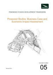
A1A B C D E F G H I J K L M NLodge12Langley Woodhouse34St BenedictTennisCourtPresbyteryThe BridgettineConventAstraeaLarkswoodPine CottageParkspringLodgePantilesThe FirsWoodcroftPostsWoodCottageDickTurpinsCottageSpringfield CottagesHollydeneLB70.4m70.1mMastHill ViewHome FarmGantryCherryOrchardFarmCherry OrchardFarm BungalowPondGantryBlanchard's Farm55.6mBelleFarmLodgeBelle FarmCottageNursery57.3mThe OaksLong CoppicePondPondNSevenhills FarmWeirPlanning Application BoundaryPROPOSED ROUTES <strong>AND</strong>LIMITS OF DEVIATIONPrimary RoadsSecondary RoadsNOTE - Cycle paths are included withinthe Roads and Development Cells shown.Controlled PermissivePedestrian Access (+/- 10 m)Footpaths (+/- 10m)Black Park link pathEdge of secure private land (+/- 10m)Location of Proposed New Access from<strong>Pinewood</strong> Road.- Refer to P-A-003 Rev DLocation of Proposed New EmergencyAccess from Sevenhills Road.- Refer to P-A-004 Rev DLimits of DeviationRoad Edge +/- 2 mts.Road Edge + 5 mts/ - 10 mts.Road Edge +/- 10 mtsNOTE - preservation of hedgerows andtrees supercedes any inference ofencroachment by a limit of deviationG:\Jobs\224788-10 PSB - ARAS\4-03 Drawings\4-03-01-02 Arch\Planning\P-P-005.dwg 23 Jan 2013 15:24:49 id: 294DE43A-ADB0-441C-A1F8-75AFEFB18F91 Amparo.GalvanDromenagh5FarmStrawberry WoodPondDromenaghFarm House6- 19/ 12/12Issued for Outline Planning ApprovalPondIssueDate7Black ParkPondsKnoll HouseHeathwoodArup AssociatesPondBrattonCattle Grid<strong>Pinewood</strong>Mews13 Fitzroy Street London W1T 4BQ United Kingdomt +44 20 7755 2525www.arupassociates.comKey Plan8TCBIssuesBaney9LBChardanHouseAlburyHouseLaurel CourtClient<strong>Pinewood</strong> <strong>Studios</strong> Ltd.Job Title<strong>Pinewood</strong> <strong>Studios</strong>Development FrameworkSpring1060.6mDrawing TitleSite Access and CirculationPondPark Lodge FarmGamekeepersCottageIssuesFB49.1mScale at A11:2500DisciplineMasterplanning11010m50m100m250mIver HeathBrackenwoodPondLBMapping reproduced by permission of Ordnance Survey onbehalf of HMSO. © Crown copyright and database right 2012.All rights reserved.Ordnance Survey Licence number 100018033Stag andJob No224788-00Drawing NoP-P-005Drawing StatusPLANNINGIssue0hHoundsDellfield FarmDo not scale(PH)© Arup Associates
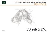
A1A B C D E F G H I J K L M NLodge12Langley Woodhouse34St BenedictTennisCourtPresbyteryThe BridgettineConventAstraeaLarkswoodPine CottageParkspringLodgePantilesThe FirsWoodcroftPostsWoodCottageDickTurpinsCottageSpringfield CottagesHollydeneLB70.4m70.1m1.09W12.25W12.24W22.26W12.28flexMast2.23W22.27W22.08S12.7S12.222.6S12.21O1entrancearchwayandkioskHill View2.5S12.20W1Home Farm2.15W22.18W22.16flex2.19W12.04S12.172.09O22.03S1Gantry2.11W12.13W1WCherryOrchardFarmCherry OrchardFarm BungalowPondGantryBlanchard's Farm55.6mBelleFarmLodgeBelle FarmCottageNursery57.3mThe OaksLong CoppicePondPondNSevenhills FarmWeirWBuilding Ridge Height Storeys(AGL)Limits of Deviation5.0 m min - 8.0 m max 1-25.0 m min - 11.0m max 1-210.0 m min -14.0m max 2-312.0 m min -17.0m max 3-415.0 m min - 21.5m max 1-4Underground waste watertreatment plan'Max' = Upper Limit'Min = Lower LimitFor further explanation including eavesheights refer to typical buildings parameterdrawingBuilding Plot Edge +2 mts / -10 mts.Building Plot Edge +5 /-10 mts.Building Plot Edge +/- 10 mts.G:\Jobs\224788-10 PSB - ARAS\4-03 Drawings\4-03-01-02 Arch\Planning\P-P-006.dwg 23 Jan 2013 15:25:33 id: 68D2D5E4-8F9C-4A40-A216-13D60193A13D Amparo.Galvan5Strawberry WoodPondentrancearchway2.29O12.12W22.01S12.10W22.02S12.14W2DromenaghFarmDromenaghFarm House61.06MP2.31O21.04W21.02S12.30O2O10 XXXXXX / /Issued for Outline Planning Approval7PondBlack ParkCattle GridPondPonds1.05W21.08W11.01O2bKnoll HouseHeathwoodBratton<strong>Pinewood</strong>MewsIssueDateArup Associates13 Fitzroy Street London W1T 4BQ United Kingdomt +44 20 7755 2525www.arupassociates.com1.03S11.07O3Key Plan8TCBIssues1.10O1Baney9LBChardanHouseAlburyHouseLaurel CourtClient<strong>Pinewood</strong> <strong>Studios</strong> Ltd.Job Title<strong>Pinewood</strong> <strong>Studios</strong>Development FrameworkSpring1060.6mDrawing TitleBuilding PlotsPondPark Lodge FarmGamekeepersCottageIssuesFB49.1mScale at A11:2500DisciplineMasterplanning11010m50m100m250mIver HeathBrackenwoodPondLBMapping reproduced by permission of Ordnance Survey onbehalf of HMSO. © Crown copyright and database right 2012.All rights reserved.Ordnance Survey Licence number 100018033Stag andJob No224788-00Drawing NoP-P-006Drawing StatusPLANNINGIssue0hHoundsDellfield FarmDo not scale(PH)© Arup Associates
A1A B C D E F G H I J K L M N123412750 21500194001025015500S1 - SOUNDSTAGE TYPE 1 S1 - SOUNDSTAGE TYPE 2O1 - OFFICE TYPE 11275010250S1 - SOUNDSTAGE W1 - WORKSHOP W2 - WORKSHOPS3 - FLEX2150019000300012750102503000155001700014500300085005908O1- OFFICE TYPE 2 O1 - OFFICE TYPE 3O2 - OFFICE TYPE 1O2 - OFFICE TYPE 2O2 - OFFICE TYPE 2O2b - OFFICE59088500W1 - WORKSHOP TYPE 1 W1 - WORKSHOP TYPE 1 W1 - WORKSHOP TYPE 185001000078951700014500 100007895W2 - WORKSHOP TYPE 1 W2 - WORKSHOP TYPE 2 W2 - WORKSHOP TYPE 31000078952130018750O3- OFFICES3 - FLEX SOUNDSTAGE/WORKSHOPO1 - OFFICE O2 - OFFICE O3 - OFFICEMP - PARKING16000135003000160001350030001400012903,03Scale at A1_ 1:2001000032 ft clear height9000300027003000ENERGY-CENTREMP - Multistorey ParkingNOTE For all Type Sections- Building's width varies according to the plot- All building height parameters are measured from FFL (finished floor level). The FFL of eachbuilding is assumed to be 150 mm above AOD finished plot levels defined in P-P-003300070004100G:\Jobs\224788-10 PSB - ARAS\4-03 Drawings\4-03-01-02 Arch\Planning\P-P-007.dwg 23 Jan 2013 15:26:25 id: 29DA66B7-DB8A-4A43-83DF-CE36765A94B0 Amparo.Galvan5102 10 2 1010 10 51.30O2aBA6Plot referenceTypePlot areaNOTE:To be read in conjunction with P-P-0060 XXXXXX / /Issued for Outline Planning ApprovalIssueDateB7Arup AssociatesA13 Fitzroy Street London W1T 4BQ United Kingdomt +44 20 7755 2525www.arupassociates.comKey PlanLikely area8B9AClient<strong>Pinewood</strong> <strong>Studios</strong> Ltd.Maximum Area (Maximum width)Maximum Area (Maximum length)Job Title<strong>Pinewood</strong> <strong>Studios</strong>Development FrameworkMaximum Area (Average length and width)1010Drawing TitleAreas and Dimensions by Plot18 / 9 *10BAScale at A1DisciplineVARIESArchitecture11Minimum areaWidth equal to 18m if plot depth >25mand 9m if plot depth < or = 25m*(Soundstages plots minimum width=36)Job No224788-00Drawing NoP-P-007Drawing StatusPLANNINGIssue0hDo not scale© Arup Associates
30 <strong>Pinewood</strong> <strong>Studios</strong> Development Framework | <strong>PRINCIPLES</strong> <strong>AND</strong> <strong>PARAMETERS</strong>
<strong>Pinewood</strong> <strong>Studios</strong> Development Framework | <strong>PRINCIPLES</strong> <strong>AND</strong> <strong>PARAMETERS</strong>0531Explanation of Parameters
32 <strong>Pinewood</strong> <strong>Studios</strong> Development Framework | <strong>PRINCIPLES</strong> <strong>AND</strong> <strong>PARAMETERS</strong>05 <strong>PARAMETERS</strong> EXPLANATION5.1 OverviewThe proposed development is set out in a series of ParameterPlans, listed below, that define the key elements of the proposals.Each element is defined in terms of its location and configurationwithin the site, with degrees of tolerance.The degrees of tolerance are applied to ensure there is sufficientflexibility in the proposals to accommodate the potential forrelatively minor changes in location, size, shape and alignmentof the key elements of the scheme given that, at this stage, theproposals are in outline only. At the detailed design stage it maybe necessary to make adjustments to the position of individualbuildings or roads within the site to accommodate as yet unsurveyedground or site conditions that conflict with the position shown in theplans. The degree of flexibility provided in the Parameter Plans hasbeen tailored to apply stricter limits to the size and position of thedevelopment at sensitive edges, or adjacent to retained landscapefeatures, and allows more latitude in less critical areas.The alignment, layout and size of the plots, buildings, roads andopen spaces shown in the Parameter Plans are based on theintended configuration of the proposals. The flexibility defined inthe Parameter Plans can be applied through a limited degree ofexpansion or contraction from the defined edge positions shownon the plans. In the case of individual buildings, the flexibility isprovided, and limited to, expansion or contraction in the width,length and height of each building.
<strong>PARAMETERS</strong> EXPLANATION<strong>Pinewood</strong> <strong>Studios</strong> Development Framework | <strong>PRINCIPLES</strong> <strong>AND</strong> <strong>PARAMETERS</strong>335.2 StructureThe following elements of the scheme are defined with ParameterPlans:Land use, development quantum, and layout• Parameter drawings P-P-003 and P-P-004 are to be read inconjunction with each other.• P-P-003 indicates the built development zones and their upperand lower limits of ground level. The Parameter Plan defines theparts of the site proposed for development, including new andretained built areas of the <strong>Studios</strong>. This shows the ‘footprint’ ofland within the site that is proposed for siting the buildings andfacilities of the <strong>Studios</strong>.• P-P-004 cross references the numbered zones to givemaximum floor areas in sqm GEA format for buildings to bedeveloped in each one.Green space, landscape and ecologyMovement, access and circulation• P-P-005 sets out the primary and secondary road system andfootpaths proposed for the site, allowing for tolerance on thealignment of the roads.Massing and building scale• Parameter drawings P-P-006 and P-P-007 are to be read inconjunction with one another.• P-P-006 defines the location of each proposed building plotwithin the site, and the upper and lower limits of height, length,and width of each building using a set of height ranges, buildingtype codes and horizontal limits of deviation• P-P-007 contains a schedule and diagrams to be read withthe Parameter Plan drawing, tabulating these dimensions foreach of the main building types and each building plot. Furtherexplanation is set out within Section 3 of this document.• P-P-001 shows the green space where there is no builtdevelopment• P-P-002 defines the proposed uses and functions of thelandscape and open areas of the site, including those areasdesignated for ecological enhancement, sustainable drainage,amenity and landscape buffers for visual screening.
<strong>PARAMETERS</strong> EXPLANATION34 <strong>Pinewood</strong> <strong>Studios</strong> Development Framework | <strong>PRINCIPLES</strong> <strong>AND</strong> <strong>PARAMETERS</strong>5.3 Development zones, land use and sitelevelsP-P-003 defines the development zones, uses, and the upper andlower limits of horizontal deviation and of ground surface.Also shown are colour coded limits of deviation for the edges of thedevelopment zones which allow for a small amount of flexibility whileproviding a commitment to containing the building positions within aset area.Limits of deviation have been informed by the assessed level ofsensitivity of any particular edge in relation to ecology and visualimpact.Site levels are used in conjunction with upper and lower limits ofbuilding height explained in P-P-006 and P-P-007 to ascertainmaximum effect building envelopes used in the EnvironmentalStatement. The building height parameters are measured from the topof the ‘Finished Floor Level’ (FFL - the internal floor surface) to thehighest part of the roof envelope. The FFL is assumed generally to be150mm above the site levels, shown Above Ordnance Datum (AOD).P-P-004 lists the maximum footprints and GEA’s permitted by typesof building. Even though a development cell may expand or contractwithin its limit of deviation, the total area is fixed.PARAMETER PLAN P-P-003
<strong>PARAMETERS</strong> EXPLANATION<strong>Pinewood</strong> <strong>Studios</strong> Development Framework | <strong>PRINCIPLES</strong> <strong>AND</strong> <strong>PARAMETERS</strong>35+5M+5M-10M-10M +10M-10MA-10M+2MDIAGRAM SHOWING HOW DEVIATION CODING IS APPLIED+5M -5MA 1A 2-10M +10M+5M -5 M+0M +2MENLARGED AREA OF SHEET DEMONSTRATING APPLICATION OF LIMITS OF DEVIATIONAREA A = AREA A1 = AREA A2THE TABLE SHOWN IN P-P-004 (SEE AT FULL SCALE EARLIER IN THEDOCUMENT)
<strong>PARAMETERS</strong> EXPLANATION36 <strong>Pinewood</strong> <strong>Studios</strong> Development Framework | <strong>PRINCIPLES</strong> <strong>AND</strong> <strong>PARAMETERS</strong>5.4 Green space and landscaping and ecologyThe Green Space and Landscaping and Ecology parameter plansoutline how the development will commit to providing green spacewithin which a range of landscaping and ecological measures willprovide amenity as well as ecological and visual mitigation.The defined limits of deviation allow for small amounts of flexibility asdemonstrated in the diagram (right).P-P-001 (Green Spaces) defines the areas of the site in which therewill be no built development. The treatment of these areas are thendetailed in P-P-002.Parameter Plan P-P-001P-P-002 defines the manner in which areas within the overall (green)space area will be treated in terms of landscaping, in particular toprovide the proposed level of screening and ecological enhancementfor the framework.Parameter Plan P-P-002
<strong>PARAMETERS</strong> EXPLANATION<strong>Pinewood</strong> <strong>Studios</strong> Development Framework | <strong>PRINCIPLES</strong> <strong>AND</strong> <strong>PARAMETERS</strong>37Enlarged Area of Sheet demonstrating application of varying limits of deviation
<strong>PARAMETERS</strong> EXPLANATION38 <strong>Pinewood</strong> <strong>Studios</strong> Development Framework | <strong>PRINCIPLES</strong> <strong>AND</strong> <strong>PARAMETERS</strong>5.5 Site access and circulationP-P-005 is the site access and circulation plan defining the road layoutstructure, with upper and lower limits of deviation.Where road layouts are close to ecological habitat corridors they havea smaller allowable deviation.It also shows the areas where access points to the application sitewill be situated and the approximate locations of pedestrian and cycleroutes where they are not incorporated into the roads (referenceproposed site access plan).The entrance access from the public highway is described in moredetail in the transport and landscape drawings.Road positions have a compatible relationship with building plots anddevelopment zones whereby the allowable deviations for each arelinked, as described later in this chapter.Parameter Plan P-P-005
<strong>PARAMETERS</strong> EXPLANATION<strong>Pinewood</strong> <strong>Studios</strong> Development Framework | <strong>PRINCIPLES</strong> <strong>AND</strong> <strong>PARAMETERS</strong>39LIMIT OF DEVIATION +/- 2LIMIT OF DEVIATION +/- 5LIMIT OF DEVIATION +/- 10THE GREY LINES DEFINE THE MOST LIKELY ROAD POSITIONS <strong>AND</strong> THE BOUNDINGCOLOURED LINES DEFINE UPPER <strong>AND</strong> LOWER LIMITS OF DEVIATION.width, ‘w’ can vary within the limits of deviation22 2wwzone of deviationRoad widthw5525 5wALLOWABLE POSITION MOVED PARALLELTHE MAXIMUM DEVIATION ALLOWED INTHAT DIRECTIONALLOWABLE POSITION MOVED PARALLELIN THE OPPOSITE DIRECTION TO THEMAXIMUM DEVIATION ALLOWED IN THATDIRECTIONALLOWABLE ROAD POSITION WITHIN THELIMITS SET
<strong>PARAMETERS</strong> EXPLANATION40 <strong>Pinewood</strong> <strong>Studios</strong> Development Framework | <strong>PRINCIPLES</strong> <strong>AND</strong> <strong>PARAMETERS</strong>5.6 Building layout andmassingThe development Parameter Plans include provision for site massingwhich meets the quantum set out in the planning application whileimposing control measures on building height, length and width andlocation to control landscape and visual impact on the surroundingarea.Within these parameters, the separation of buildings has beenconsidered to allow for fire safety and to ensure that the functionalrequirements for internal working and external filming are met.A colour coded set of tolerances are applied to the edge of buildingplots to allow for limited flexibility of building position, orientation andsize, to meet future demands.P-P-006 defines the building plot locations and upper and lower limitsof deviation for those plots. It also codes each plot by height categoryand building type, which in turn restricts length and width.P-P-007 is read alongside P-P-006 and provides further detailregarding maximum and minimum footprints, and GEA floor areas foreach plot, as well as maximum and minimum eaves and ridge heights,lengths and widths.PARAMETER PLAN P-P-006ENLARGEMENT
<strong>PARAMETERS</strong> EXPLANATION<strong>Pinewood</strong> <strong>Studios</strong> Development Framework | <strong>PRINCIPLES</strong> <strong>AND</strong> <strong>PARAMETERS</strong>41<strong>PARAMETERS</strong> TABLE P-P-007
<strong>PARAMETERS</strong> EXPLANATION42 <strong>Pinewood</strong> <strong>Studios</strong> Development Framework | <strong>PRINCIPLES</strong> <strong>AND</strong> <strong>PARAMETERS</strong>5.7 How the parameters are applied3 - Equilibrium1 - Plot Area, PEach building plot is demarcated by a blue zone.The tone of blue is an easy short-hand reference tothe buildings upper and lower limit of height.PThe sum of all of the plot areas, multiplied by the maximum numbers ofstoreys would make an implied GEA far higher than the maximum GEA’sset by the Development Zone Parameter Table P-P-004.The maximum GEA’s for each zone are calculated by totalling the likelyGEA’s for each building plot.A plot reference number and building type code arealso shown.The plot area is P and can vary within the tolerancesshown (explained below)x2 - Likely Footprint, LThe likely building outline shown illustratively willsit within that plot.L++TotalPlot AreaTotal Plot Area >> Maximum GEAIt may be the full extent of the building plot areaNon Permittedis utilized, but in most cases the likely footprint isslightly smaller.The likely building outline has an area, L.Likely Footprint++=MaximumGEA
<strong>PARAMETERS</strong> EXPLANATION<strong>Pinewood</strong> <strong>Studios</strong> Development Framework | <strong>PRINCIPLES</strong> <strong>AND</strong> <strong>PARAMETERS</strong>434 - FlexibilityThe illustrative drawings show a realistic view of the scheme as fullydeveloped but within the zonal GEA maximums set by the ParameterPlans.Thus, if a building is developed to its maximum allowable GEA on asingle plot, the amount it exceeds its likely GEA by would have to becompensated for elsewhere in the scheme by developing one or moreother plots to a lesser extent.A building which is within the lower and upper limits of deviationof footprint area, but smaller than the Plot Area could be situatedanywhere within that plot, and could also be rotated within the plot ifthere is enough space.
<strong>PARAMETERS</strong> EXPLANATION44 <strong>Pinewood</strong> <strong>Studios</strong> Development Framework | <strong>PRINCIPLES</strong> <strong>AND</strong> <strong>PARAMETERS</strong>5.7 How the parameters are applied5 - Maximum footprintEach building has a maximum footprint of area, A.General caseThe proportion of the footprint can change providing it fits withinthe maximum and minimum width, height and length defined in the“Building heights, widths and lengths, upper and lower limits” table.P > LP > A > L ( Maximum Length)Throughout this document, the use of the word ‘maximum’ isequivalent to ‘upper limit’ and the word ‘minimum’ is equivalent to‘lower limit’.AIn some cases the Maximum footprint APlot Area (P) is greater than Likely Area (L)LPP > A > L ( Maximum Depth)Pis equal to the Likely footprint, Land also equal to the Plot Area, P.In general though,AP is greater than A is greater than L.KeyPlot Area (P)Maximum Area (A)Likely Area (L)Maximum Area (A) is greater than Likely Area (L)but smaller than Plot Area (P)PIf a building maximum footprint is less than the plot area, it could beplaced anywhere within the plot area.It could also be extended to the maximum length - providing it doesnot exceed the maximum footprint areaORIt could be extended to the maximum width of the plot providing it doesnot exceed the maximum width in the table.
<strong>PARAMETERS</strong> EXPLANATION<strong>Pinewood</strong> <strong>Studios</strong> Development Framework | <strong>PRINCIPLES</strong> <strong>AND</strong> <strong>PARAMETERS</strong>456 - Minimum FootprintEach building has a minimum footprint of area, A.It can change proportion providing it fits within the maximum and minimumwidths and lengths defined in the “Building heights, widths and lengths, upper andlower limits” tableIn most cases a building minimum width is 9m if the plot is less than 20m in totalwidth.In most cases a building minimum length is 20m shorter than the maximumlength of the plot.7 - Plot edge deviationOn the building plots parameter plan, each plot has colour coded edges indicatingupper and lower limits of deviation.Three margins of deviation are proposed.+2/-10m : meaning the edge can move outwards 2m and inwards 10m- applied to building plots with high level of sensitivity to ecological and visualimpact+5m/-10m : meaning the edge can move outwards 5m and inwards 10m- applied to building plots with moderate levels of sensitivity+/-10m : meaning the edge can move outwards and inwards 10m- applied to building plots assessed to have low levels of sensitivity
<strong>PARAMETERS</strong> EXPLANATION46 <strong>Pinewood</strong> <strong>Studios</strong> Development Framework | <strong>PRINCIPLES</strong> <strong>AND</strong> <strong>PARAMETERS</strong>8 - Road and plot interactionLIKELY POSITIONAll roads and plots are drawn in their most likely location. Limits ofdeviation of plots and their adjacent primary and secondary roadsare designed to be compatible. Three examples are shown on theopposite page.LIMIT OF DEVIATION +2/-10LIMIT OF DEVIATION +5/- 10LIMIT OF DEVIATION +/- 2LIMIT OF DEVIATION +/- 5LIMIT OF DEVIATION +10/-10LIMIT OF DEVIATION +/- 10PLOT LIMITS OF DEVIATIONROADS LIMITS OF DEVIATION
<strong>PARAMETERS</strong> EXPLANATION<strong>Pinewood</strong> <strong>Studios</strong> Development Framework | <strong>PRINCIPLES</strong> <strong>AND</strong> <strong>PARAMETERS</strong>47Example 1Example 2 Example 3In this example one road moves away from the centre of theplot by 10m and another moves towards the centre of theplot by 10m.The result is a plot where the orientation has changed butcould be of a comparable area to its originally intendedsize.The edge of the plot moving outwards by 10m is a degreeof deviation that is not applicable in a visually sensitivelocation.In this example a road moves towards the centre of theplot by up to 10m, and the other road moves away fromthe plot centre by 5m.The result is likely to be a smaller overall plot size butof the same orientation as the originally intend plotposition.The edge of the plot moving out by 5m is a degree ofdeviation that is applicable in an area of moderatesensitivity, and will be a low building with adequatescreening for this to be of insignificant consequence.The roads in question could move up to 5m from theirintended position but the constraints on the building aremore onerous meaning it can only move 2m beyond itsoriginally intended position.Highly constrained limits of deviation like this have beenused in the scheme where the sensitivities of the sitenecessitate a particular building scale and location.EXAMPLE 1 EXAMPLE 2 EXAMPLE 3
<strong>PARAMETERS</strong> EXPLANATION48 <strong>Pinewood</strong> <strong>Studios</strong> Development Framework | <strong>PRINCIPLES</strong> <strong>AND</strong> <strong>PARAMETERS</strong>9 - The ‘maximum effect’As stated in the opening part of this explanation the limits ofdeviation do not allow for a bigger development than is describedby the development zones parameter table. Nevertheless it hasbeen important to understand the plot area deviations as part oflandscape and visual impact assessment.LikelyFootprint (L)In theory, a plot could expand by up to 20m along its length andwidth. In practice, the limits set in the parameter tables preventbuilding masses from occupying their entire building plot. Themaximum effect has been modelled along the principles set outbelow for the development of verified views. Refer to the ES forverified views.LIKELY CASEPlot area (P)MAXIMUM EFFECT VOLUMEMaximum area (A)The maximum effect envelope for buildings in any plot is definedby extending the edges of the volume to the points of maximumdeviation.The likely building mass has been modelled and sits within thatvolume. Alternative building positions and shapes could existanywhere within that theoretical envelope - but only up to themaximum footprint area, and maximum GEA allowed within theparameter tables.maximum effectVolumeIt would not possible to develop a scheme where all plots arebuilt to their maximum effect envelope because of the principle ofequilibrium outlined above.MAXIMUM EFFECT VOLUME IS GREATER THAN OR EQUALTO LIKELY CASE <strong>AND</strong> IS EXAGGERATED FOR THE PURPOSESOF THESE DIAGRAMS
<strong>PARAMETERS</strong> EXPLANATION<strong>Pinewood</strong> <strong>Studios</strong> Development Framework | <strong>PRINCIPLES</strong> <strong>AND</strong> <strong>PARAMETERS</strong>49The illustrations here demonstrate the likely building volumes used inthe Illustrative Masterplan, the maximum effect volumes generated frommaximum building heights and plot offsets and the two overlaid.THE LIKELY BUILDING ENVELOPE GENERATED FROM THE MASSING <strong>AND</strong> SITE LEVEL PARAMETERPLANSIt should be noted that the ‘maximum effect volume’ infers a scale ofdevelopment which would be impossible to achieve under the constraintsimposed by the parameter tables in P-P-004 and P-P-007. What therepresentation of the maximum effect volume is useful for is providing anoutline in three dimensions which has been used to generate verified viewsfrom multiple locations which are consistently showing the maximum effect.These views have also been used to develop mitigation strategies whichlandscape parameters achieve.THE MAXIMUM BUILDING ENVELOPE GENERATED FROM THE MASSING <strong>AND</strong> SITE LEVEL PARAMETERPLANSTHE LIKELY <strong>AND</strong> MAXIMUM BUILDING ENVELOPE GENERATED FROM THE MASSING <strong>AND</strong> SITE LEVELPARAMETER PLANS
<strong>Pinewood</strong> <strong>Studios</strong> Development Framework | <strong>PRINCIPLES</strong> <strong>AND</strong> <strong>PARAMETERS</strong>51
52 <strong>Pinewood</strong> <strong>Studios</strong> Development Framework | <strong>PRINCIPLES</strong> <strong>AND</strong> <strong>PARAMETERS</strong>PINEWOOD STUDIOSDEVELOPMENT FRAMEWORKFEBRUARY 2013