Vegetated Geogrids
Vegetated Geogrids
Vegetated Geogrids

You also want an ePaper? Increase the reach of your titles
YUMPU automatically turns print PDFs into web optimized ePapers that Google loves.
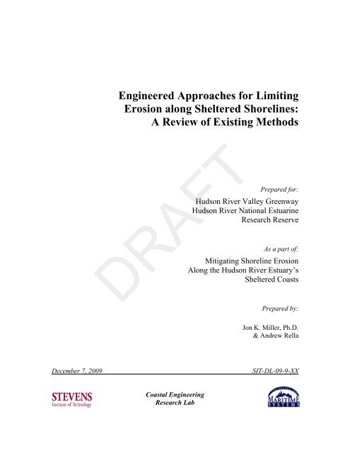
Engineered Approaches for LimitingErosion along Sheltered Shorelines:A Review of Existing MethodsPrepared for:Hudson River Valley GreenwayHudson River National EstuarineResearch ReserveAs a part of:Mitigating Shoreline ErosionAlong the Hudson River Estuary’sSheltered CoastsDRAFTPrepared by:Jon K. Miller, Ph.D.& Andrew RellaDecember 7, 2009SIT-DL-09-9-XXCoastal EngineeringResearch Lab
IntroductionThe purpose of this document is toprovide an overview of the engineeredapproaches currently being utilized tomanage erosion along shelteredshorelines. In their natural state,shorelines tend to be dynamic, cyclingthrough periods of erosion and accretionin response to changes in weatherpatterns and sediment supply. Alongdeveloped shorelines, such as those ofthe Hudson River Estuary, the dynamicnature of shorelines often conflicts withrequirements to protect private propertyand infrastructure. In these areas avariety of engineered erosion controlapproaches are employed as a way ofreducing or eliminating further land loss.Designing an appropriate shoreprotection measure for a particularlocation reflects a delicate balancebetween the required protection leveland factors such as cost, aesthetics, andenvironmental impact.In general, the lower energy alongsheltered coastlines allows for greatercreativity in designing shore protectionprojects; therefore a variety of differentengineering approaches have beendeveloped. These approaches rangefrom shoreline hardening via bulkheads,revetments, gabions and other structures,to softer more natural methods such asvegetative plantings. In 2007, theNational Academies Press released thereport, Mitigating Shore Erosion AlongSheltered Coasts, which advocated thedevelopment of a new managementframework within which decisionmakers would be encouraged to considerthe full spectrum of options available.The initial phase of this study begins toaddress some of the recommendationsmade in the report by first identifyingand documenting as many differentengineered shoreline stabilizationapproaches as possible. In subsequentphases, a more detailed treatment of theapproaches most applicable to theHudson River Estuary will be given.BackgroundThere are many potential causes ofshoreline erosion and bank instability.The U.S. Army Corps of Engineers(Davis and Maynord, 1998) explicitlyidentified the following seven, but notedthere are others as well: wind and boatwaves, boat induced currents, channelmeander, channel braiding, ice anddebris, water level fluctuations, and flowconstrictions. The Hudson River estuaryis significantly influenced by all of theabove. The diversity of the estuary issuch that distinct regions exist where oneor more of the processes may dominate.As a result, historically a variety ofapproaches have been taken tostabilizing the shoreline.Miller (2006) performed an inventory ofHudson River shorelines and proposed afive level classification scheme. Of theshorelines inventoried, 42% were hardengineered, 47% were natural, and 11%were natural with remnants ofengineering structures. The mostcommon shoreline structure was rip-rap(32%), followed by woody (29%) andunvegetated (16%) slopes. Thedominant substrate found within theregion was unconsolidated rock (52%),mud/sand (16%) and mixed soil/rock(12%). Historically in the Hudson RiverEstuary, as elsewhere, ecological impactwas rarely considered during the designof shore protection works. The moderntrend however is to place significantemphasis on such considerations.DRAFT
MethodologyA systematic approach was used in thepreliminary analysis presented here tofacilitate the comparison of shoreprotection alternatives. Each shorelinestabilization technique is qualitativelyevaluated in four categories: Approach,Construction Cost, Maintenance Cost,and Adaptability. Approach refers to thetype of shore protection strategy beingemployed and ranges from “hard” forstructures such as vertical bulkheadswhich create a hard edge, to “soft” formethods such as vegetative planting,which maintain a more natural soft edge.Construction Cost takes into account thetypical costs associated with initialconstruction, while Maintenance Costrefers to the cost of maintaining thesystem over its lifetime. Adaptabilityconsiders the effort required to modifyin-place projects to handle newconditions brought on by climate changeor other factors. As summary of thesequalitative evaluations is presented in atable at the end of the document.More detailed information is presentedin the description which follows theevaluations. These descriptions rangefrom several pages for the moretraditional, well-studied approaches tobrief synopses of newer, less wellstudied techniques. Wherever possible,pictures and figures showing crosssectionsand/or typical installations areprovided. To assist in comparingvarious alternatives, the descriptions arebroken down into the following sixcategories: Description, Design andConstruction, Adaptability, Advantages,Disadvantages, and Similar Techniques.The Description section provides a shortdiscussion of the specified approach.The Design and Construction sectioncontains information on some of thebasic design and constructionconsiderations associated with eachapproach. At this stage, the descriptionsof the design and construction processare kept fairly brief. It should be notedthat the information presented in thissection is intended only to relay thebasic design principles and that detaileddesigns require much more informationthan provided in this document. Costinformation where available, as well asoperation and maintenanceconsiderations are also presented in thissection. The Adaptability sectioncontains information related to the longterm viability of the specified approach.Factors such as expected lifespan,durability, and the ease of modificationare considered. The Advantages andDisadvantages sections differ from theprevious ones in format, in that they arepresented as bulleted lists intended toconcisely summarize both the positiveand negative attributes of a givenmethod. Similar Techniques lists thealternative approaches or methods whichare most similar to the one beingdiscussed. Finally, a glossary ispresented at the end which providesconcise (one or two sentence)descriptions of the approaches discussedin the main body of the literature review.DRAFT
BulkheadsApproachConstruction CostSoft Hard Low HighMaintenance CostAdaptabilityLow High Low HighDescriptionBulkheads are perhaps the most commonstructure found along shelteredshorelines. The primary purpose of abulkhead is to prevent the loss of soil byencapsulating it behind an oftenimpervious vertical wall. Bulkheads aremost common at the base of bluffs orsteep shorelines, in areas where land hasbeen reclaimed, and in locations wherespace is limited (marinas for example).Bulkheads are frequently found nearmooring facilities, in harbors andmarinas, and along industrializedshorelines. One of the major drawbacksassociated with bulkheads is that theycan increase erosion on adjacentshorelines due to flanking effects.their size and weight for support.Cantilevered bulkheads are supported atone end, similar to a cantilever beam,and rely on their embedment for support.Anchored bulkheads are similar tocantilevered bulkheads, with ananchoring system added for additionalsupport. Due to their supportmechanism, gravity bulkheads andcantilevered bulkheads are typicallylimited to lower energy, lower heightapplications.Bulkheads can be constructed of manydifferent materials. A timberpile/wale/sheet system is a commonstructural configuration. It is generallyeconomical material, but has limitedstrength characteristics for high wallheights. Preservative treatment isessential for combating degradation dueto marine organisms. The service life oftimber bulkheads tends to be less than 25years.DRAFTConcrete pile panel configurations offeran alternative to timber bulkheads thatcan provide a service life of 30+ years ifthe correct mix design and proper marinestructural design are implemented.Figure 1: Typical bulkhead cross-section.Bulkheads can be broadly classified onthe basis of their main supportmechanism. Gravity bulkheads rely onSteel and aluminum sheet piling are alsocommonly used to construct bulkheads.Aluminum provides good corrosionresistance; however its low strengthlimits its use to low-height applications,and softer substrates. Steel provides
excellent strength characteristics for highwall exposure applications, has aninterlocking seal, and is generally easyto install, even in harder substrates.Properly coated and maintained, steelbulkheads can have an estimated servicelife in excess of 25 years.Figure 2: Timber pile/wale bulkheadFigure 3: Concrete bulkhead.More recently, synthetic materials havebeen used in bulkhead construction withincreasing frequency. Vinyl andfiberglass products offer severaladvantages over traditional materialsincluding potentially significant costsavings, coupled with service lives of upto 50 years. In terms of strength,synthetic products are typically limitedto moderate wall heights and installationin softer substrates.Figure 4: Steel sheet pile bulkhead.Figure 5: Fiberglass sheet pile bulkhead.Design & ConstructionAlthough the actual design steps willvary from project to project, there are aseries of steps that are typical. The firststep is to determine the site parameterssuch as: required water depth, variationof water level in front of sheet piling, theground water level behind the bulkhead,the level of finished grade behind thebulkhead, the soil conditions (bothnative and for any additional backfillmaterial), and the anticipated amount ofvertical surcharge loading on the groundbehind the bulkhead. This informationcan be used to construct earth pressurediagrams for the inner and outer faces ofthe bulkhead. These diagrams can thenbe used as the basis for determining: thedepth of the sheet pile penetration andthe pull in the tie rods, the bendingDRAFT
moment in the sheet piling, the requiredthickness of the sheet piling, the size andspacing of any tie rods, the bendingmoment and required size of wales (ifthey are utilized), and the requiredsize/location of the deadman (if utilized).The characteristics of the substrate onwhich a bulkhead is to be constructed isextremely important. With the exceptionof gravity bulkheads, bulkheads rely onembedment for their strength, thereforethey must be anchored far enough intothe ground in order to be stable.Interlocking sheet piles can be drivendeeply into the ground if the foundationis sand or earth; however holes must bedrilled and grout or concrete used toanchor the sheets if bedrock is present.Depending on the expected loadingconditions, a gravity bulkhead may alsobe appropriate if bedrock is present.Wave conditions also play an importantrole in determining the appropriatenessof a bulkhead for a particular site. Ifconstructed in a location where waveswill continually beat against the face ofthe bulkhead, proper materials must beused to withstand these strong forces.Bulkheads should not be constructedwhere wave action will cause excessiveovertopping of the structure.Stability will also be impacted by thelocal water table. If there is a gradient inwater level across a structure that isunaccounted during the design phase,additional overturning moments could becreated that would compromise itsstability.Other concerns include the loads anddamages that the structure might endurefrom ice flows, and the type of activitybeing performed behind the structure.The operation of forklifts and otherheavy equipment behind a bulkhead cantransfer significant loads to the soil,which if unaccounted for during thedesign process can result in structuralfailure.Bulkheads generally have a lowmoderateinstallation cost which reflectsa balance between low material costsand high labor and equipment costs.Costs of between $500 and $1,000 perlinear foot are typical.As a general rule, bulkheads should beevaluated every five to six years.Assessing the condition of bulkheads ona regular basis can extend the service lifeof the structure. Performing preventativemaintenance or minor repairs beforethey become major concerns cansignificantly prolong the life of abulkhead. Repairs can cost anywherefrom $100-$400 per linear foot of wall.AdaptabilityBulkheads are generally not veryadaptable. As a fixed height wall,accommodation for future sea level riseis not possible without significantmodifications, potentially requiring thereplacement of the entire structure.DRAFTAdvantagesBulkheads have many advantages overother engineered shore protectionapproaches, among them are:• Bulkheads may be the mostappropriate solution for areas wherethe primary use of the shore is forfishing and boating.
• Bulkheads are very effective againstsoil erosion when dealing with bluffsor land that drops off very suddenly.• Bulkheads can be used in areaswhere there is significant waveaction.• Bulkheads have a limited structuralfootprint.• Bulkheads are fairly economical andrequire minimal maintenance.DisadvantagesBulkheads have many disadvantagescompared to other engineered shoreprotection approaches, among them are:• Wave reflection can be significant,potentially leading to hazardousconditions.• Wave reflection can also increasescour at the base of a structurepotentially leading to underminingand failure.• Bulkheads can shut off the supply ofsand and gravel to the beach,resulting in beach loss and thegradual loss of finer sediment.• Bulkheads can change importantshoreline habitats. Shoreline areasused by fish, shellfish, birds, marinemammals, and other marine life maybe damaged.• Erosion of adjacent areas may beexacerbated.Similar TechniquesAlternatives may include: gabions,revetments, walls.DRAFTand green
GabionsApproachConstruction CostSoft Hard Low HighMaintenance CostAdaptabilityLow High Low HighDescriptionGabions are wire fabric containers thatcan be used to form retaining walls, seawalls, channel linings or revetments.They are uniformly partitioned meshbaskets that are filled with cobbles orcrushed rock and form flexible,permeable and monolithic structures.Originally plants were used to constructgabions but the modern technique ofusing welded or woven wire mesh ismuch more effective and durable. Thewire that forms the gabions can begalvanized to reduce corrosion, but theycan also be coated in plastic or anotherprotective material. Gabions can bestacked vertically to create a gabionwall, or placed along a slope to create arevetment. Gabion walls are moresusceptible to structural failure andoutflanking, and also more intrusive onthe landscape. Sloping walls are morelikely to become buried by sand anddevelop a more natural landscape, whilealso allowing access to the beach.Figure 7: Terraced gabion wall.There are typically three different formsof gabion structures that can be used; thegabion basket, gabion mattress, and sackgabion. Gabion baskets and gabionmattresses are similar structures that aredistinguished by their thickness andheight. Gabion baskets are normallytaller structures that range in thicknessfrom 1.5 to 3 ft. They are appropriate inlocations where gabion mattresses can’tprovide the desired level of protection orwould be unstable under the designconditions. The gabion mattress is asmaller structure that ranges in thicknessfrom 0.5 to 1.5 ft, and whose mainpurpose is to protect the bed or bank of astream from erosion. The sack gabion isa mesh sack that is filled with rocks, siltor sand.DRAFTFigure 6: Typical gabion cross-section.The basket type construction of all threetypes of gabions allows small rocks,which normally would not be effectivein preventing erosion, to be used. This
advantage makes gabions useful whenthe cost of transporting larger stonesfrom other sites is too expensive.Compared to rip-rap projects constructedof similar sized stones, gabions requireonly about 1/3 the thickness of material.Gabions actually become more stableover time by collecting silt anddeveloping vegetation. Large vegetationmust be prevented from growing;however, because it can eventually breakthrough the gabion wire and causedamage to the structure. Gabions areflexible enough that they can yield toearth movement or slight movement intheir foundations, but remain fullyefficient and structurally sound. Thesestructures also have the advantage of selfdrainage.Design and ConstructionThere are three primary designconsiderations for gabion walls; thestability of the foundation, the velocityand shear-stress that can be withstood,and protection of the toe and flank of thestructure.The foundation on which the gabion isbuilt is very important. If the materialbeneath the gabion is silt or sand, thefoundation can be washed out throughthe baskets and the structure can fail orcollapse. To prevent this problem afilter material or filter fabric can be used.Gabions must be able to withstand thelateral shear stresses induced by amoving current, particularly if a gabionmattress is being used (because it ismore subject to movement than thegabion basket). Gabion mattresses havebeen used in high velocity waters andbeen proven effective, but still need tobe carefully designed. The equation forthe median stone size for a gabionmattress is:d0.5⎛ γ ⎞wm= SfCsCvd⎢⎜ ⎟⎢ γs− γw⎡⎣⎝⎠V ⎤⎥gdK1⎥⎦Where, C s is a stability of coefficientwith a typical value of 0.1, C v is avelocity distribution coefficient given by1.283-0.2log (R/W) with a minimumvalue of 1.0, d m is the average rockdiameter within the gabion structure, d isthe local flow depth at V, g is gravity, K 1is a side slope correction factor, R is thecenterline bend radius of the mainchannel flow, S f is a safety factor (1.1minimum), V is the depth-averagedvelocity, W is the water surface width ofthe main channel, γ s is the unit weight ofthe stone to be used, and γ w is the unitweight of water. Fischenrich (2001)reported allowable allowable shearstresses, and stream flow velocities of 10lb/sf and 14-19 ft/s, respectively forgabions.The construction of gabion structures isrelatively straightforward and does notrequire a highly skilled workforce. Thefirst step is to prepare the area on whichthe structure is to be built by smoothingthe surface. Next place a filter fabric orgravel filter to prevent the washout offine material through the voids in thegabions. The gabions themselves caneither be constructed first and thenconnected or connected and then filleddepending on the site conditions. Onceset in place, covers may be placed on thegabions and/or they may be seeded forextra stability and ecological benefit.DRAFTCompared to the other stream bankstabilization structures the cost ofgabions is one of the more expensive.Price depends mostly on requireddimensions, labor costs, availability of2.5
fill material and transport methods.Construction costs can range from$100/lf to $200/lf. This price includesthe assembly and filling of the baskets,the wire for the baskets, the stone fill,and basket closure. Normally heavyequipment is not necessary forconstruction of a gabion wall, howeverthe labor involved with basket closure issubstantial.Once in place, it is important thatgabions are routinely checked fordamage and broken wires; however theytypically require very minimalmaintenance. The most common repairsconsist of fixing broken baskets and/orreplacing missing rocks. Any largevegetation should be removed to reducethe likelihood of the baskets breaking.Erosion around the structure must alsobe very closely monitored. Undercuttingat the toe of the structure can causefailure if appropriate remediationmeasures are not taken. Finally,locations on the gabion where runoffflows over the top of the structure cancause soil erosion and must also beclosely monitored. If regular inspectionsare performed geotechnical failure canbe avoidedAdaptabilityIn terms of adaptability gabion structuresare quite flexible. Because of theirmodular nature, gabions lend themselvesto adding units to increase their heightand/or structural resiliency.AdvantagesGabions have many advantages overother engineered shore protectionapproaches, among them are:• Gabions can be used when armorstone is too costly.• Structural integrity increases overtime with the addition of sand andvegetation.• Since the structures are flexible andpermeable, scouring is reducedcompared to solid shear structures.• The porosity of the structure allowssand and dirt to accumulate andproduce vegetation.• Gabions can withstand relativelyhigh velocity flows.• Gabion walls easily fit into thecontours of the stream bank.• Gabion walls can freeze & thaw andthe shifting of the stones will haveminimal impact to the structure.• Heavy machinery is notrequired forconstruction.• Maintenance costs are minimal.DisadvantagesGabions have many disadvantagescompared to other engineered shoreprotection approaches, among them are:• They have a limited lifespan (5-10yrs) due to the breakdown of thewire mesh used to construct thebaskets.• Ultimately they break, resulting incobbles and wire mesh scattered onthe beach. This material can pose asignificant hazard.• Many people consider gabions aneyesore.• Usage is restricted to areas of lowmoderatewave energy.• Gabions are hard structures, whichreduce the sediment supply to thebeach.• Gabions alter the nearshore habitat.• Erosion in adjacent areas may beexacerbated if the structure is notproperly designed.DRAFT
• Ice and other debris can damage thewire mesh baskets.Similar Techniques• Alternatives may include:revetments, bulkheads, green walls,crib walls.DRAFT
RevetmentsApproachConstruction CostSoft Hard Low HighMaintenance CostAdaptabilityLow High Low HighDescriptionRevetments are sloping structures builtparallel to the shoreline to protect thecoastline against erosion caused by waveand current energy. Revetmentstypically use large rocks or concretearmor units to dissipate wave energy andprevent further recession of thebackshore. Because the individual unitsare susceptible to movement under theright combination of forces, revetmentsare most effective in low-moderate waveconditions. Bulkheads offer analternative for more extreme waveconditions. Revetments can be used as asupplement to a seawall or dike atlocations where both erosion andflooding is a problem.are typically steep enough to precludethe use of revetments in areas that areused for recreation and fishing.Revetments can be an effective means ofshore protection when seawalls and/orbulkheads are not considered costeffective or environmentally acceptable.Unlike solid structures, revetments mayrequire regular repairs and evenextensions to continue to provide thedesired level of protection. If a lowerdegree of protection is consideredacceptable, rip-rap slopes may be a morecost-effective alternative. Thedifference between the two being thatmuch smaller rocks can be utilized in theconstruction of a rip-rap slope.DRAFTFigure 8: Typical revetment cross-sectionThe sloping, porous nature of revetmentsreduces the amount of energy reflectedfrom the structure compared to verticaland/or impervious structures. The slopesFigure 9: Rock revetmentThe three main components of arevetment are the armor layer, the filterlayer, and the toe. The armor layer ismade up of heavy, stable material thatprotects the shoreline against erosion.
The filter layer is what supports thearmor and allows water be transportedthrough the structure. The filter is alsonecessary to prevent the underlying soilfrom washing through the armor layer.The toe protects the base of the structure,which is particularly vulnerable to scour.Stone revetments are constructed fromlarge quarry stone boulders. Dependingon the availability and transportationcosts, stone revetments can beexpensive. In ocean front applications,pre-cast concrete armor units have beenutilized in place of quarry stone whenadequately sized stones are unavailable.Concrete armor units have the advantageof being designed such that theindividual units inter-lock with oneanother, maximizing stability. Ifdesigned and constructed well, stonerevetments can be extremely durable andcan even resist damage from debris andice.Rubble revetments are constructed fromrecycled stone or concrete that has comefrom the demolition of sidewalks, streetsand buildings. Due to the nature of thesource material, rubble revetments tendto be fairly economical. Some of thedisadvantages of rubble revetments arethat they tend to be fairly unsightly, andgood quality control is required toprevent undesirable materials (metal,glass, etc.) from being mixed in with therubble.Concrete revetments are typically verycostly, but can be necessary when highvalue assets must be protected. Concreterevetments are extremely durable andcan withstand damage from debrisand/or ice.Concrete or masonry block revetmentsare large concrete, interlocking blocksstacked in a staggered or sloped manner.Due to their typically limited size,concrete/masonry block revetments areless durable then other revetments. Inaddition they are susceptible to damageby ice and/or other debris.Design and ConstructionThere are several common steps to thedesign of a revetment. First andforemost is the determination ofenvironmental parameters and projectconstraints including: the expected andextreme water level variations, theexpected and extreme wave heights,suitable armor alternatives, crestelevation (related to the expected runup),and the expected and allowableamounts of overtopping.Once the site conditions are determinedthe required size of the individual armorunits can be calculated using a formulasuch as the Hudson formula,3γHW =3K S 1 cotθD( − )DRAFTWhere, W is the weight of individualarmor units, γ is the unit weight of thearmor units, H is the design wave height,S is the specific gravity of the armorunit, cotθ is the slope of the structure,and K D is a stability coefficient. Otherdesign considerations will include:required drainage systems, local surfacerunoff and overtopping runoff, flankingat the end of the structure, toe protection,filters, and underlayers.A typical construction sequence for astone revetment consists of a series ofsteps. First the stream bank must beprepared by sculpting it into the desiredslope (typically 2:1). Next the filter
layer is prepared consisting of a geosyntheticmembrane and a layer of smallrocks, or gravel. The main armor unitsare then placed on the filter layer, withlargest rocks along the bottom of thebank. Extra protection is typicallyrequired at the toe of the structure and atthe flanks to prevent erosion in thesecritical areas.Revetments can be costly, ranginganywhere from $500/lf to $2,000/lf.Construction costs are a function ofstructure dimension, as well as theavailability and coast of transportingmaterial to the site.The individual rocks comprising arevetment can be prone to damage,displacement, or deterioration. Thisreduces the overall effectiveness of thestructure, and makes surrounding areasmore susceptible to future damage. Forthis reason, periodic inspections arerequired to identify misplaced ordeteriorated armor stones so that theycan be repaired before the damagebecomes too severe.AdaptabilityIn terms of adaptability, revetments arefairly flexible. Adding individual armorunits to extend an existing structure isusually possible, although expensive.Given the significant costs involved withthe mobilization/demobilization of theheavy equipment required forconstruction, consideration of futureconditions is most efficiently addressedprior to initial construction.AdvantagesRevetments have many advantages overother engineered shore protectionapproaches, among them are:• Individual armor units are given anallowance for movement withoutcausing the structure to becomeimpaired.• The installation is straightforward;however it does require the use ofheavy machinery.• Revetments have low maintenancerequirements and damages can beeasily repaired.• Revetments are adaptable and can beadjusted or modified to continue toprovide protection in the future.• They can withstand relatively strongcurrents.• The void spaces within the structureprovide some habitat function ascompared to shear, impervioussurfaces.DisadvantagesRevetments have many disadvantagescompared to other engineered shoreprotection approaches, among them are:• Scouring occurs at the toe and flankof the structure and can increaseerosion downstream.• Material cost and transportation canbe expensive.• Large voids due to poorly placedrocks can be a hazard.• Access to the shoreline isaltered/disrupted.• They have a significant impact onthe local landscape and can disruptsediment transport.DRAFTSimilar TechniquesAlternatives may include: gabions,bulkheads, rootwad revetments, treerevetments, green walls, and crib walls.
Rootwad RevetmentsApproachConstruction CostSoft Hard Low HighMaintenance CostAdaptabilityLow High Low HighDescriptionA rootwad is the lower trunk and rootfan of a large tree. Rootwads can beused to construct a special type ofrevetment known as a rootwadrevetment. These structures alsotypically incorporate boulders andwooden logs to provide stream bankstabilization.Typically, rootwad revetments areinstalled in series along streams withmeandering bends. In addition toproviding stabilization, the revetmentsalso provide an improved fish rearingand spawning habitat.Figure 10: Rootwad revetment cross-section.Design and ConstructionStream water level is an importantparameter in designing a root wadrevetment. Overtopping can cause thetop of the structure to scour and loseintegrity. Rootwads are also noteffective in streams where the bed hasbeen severely eroded and undercuttingof the structure is likely to occur. Toeand flank protection therefore are animportant part of the design process.Ideally rootwads should not beimplemented on streams with a rockyterrain or on narrow streams bounded byhigh banks.The construction process includesanchoring a small-medium diameter(~16”) tree trunk with rootwad into thestream bank. Trenches must also beexcavated to install footer logs for therootwad.DRAFTRootwad revetments are constructedentirely of natural materials. Materialcosts will vary depending on their sourceand availability, but are generallybetween $200 and $1,500 per rootwad.Figure 11: Rootwad revetment planview.Root wad revetments need to beinspected on a regular basis afterconstruction. During floods or times ofhigh flow, the structure can be eroded byovertopping or affected by organicdecay.
AdaptabilityIf water levels increase and overtop arootwad revetment, scour along the crestof the structure may take place and caneven initiate a total collapse of the bank.For this reason, careful monitoring is arequirement for this type of system. Inorder to accommodate rising sea levels,rootwad revetments would need to bereinstalled at higher elevations. Ideally,this should take place beforeovertopping becomes frequent, asorganic rot will decrease theeffectiveness of the structure.AdvantagesRootwad revetments have manyadvantages over other engineered shoreprotection approaches, among them are:• They provide a natural, ecologicallyfriendly form of bank stabilization.• They can improve fish rearing andspawning habitats.DisadvantagesRootwad revetments have manydisadvantages compared to otherengineered shore protection approaches,among them are:• They are typically most effective onthe banks of meandering streams.• They are susceptible to damage duerising water levels.• They are typically ineffective insandy/silty soils typically found inriver estuaries.• This technique has only recentlybeen adopted as a streamstabilization technique and itseffectiveness is still being assessed.• Rootwad revetments can not be usedin locations where the structure willbe overtopped frequently.Similar TechniquesAlternatives include: revetments, treerevetments, gabions, crib walls.DRAFT
Tree RevetmentsApproachConstruction CostSoft Hard Low HighMaintenance CostAdaptabilityLow High Low HighDescriptionA tree revetment is a revetmentconstructed of trees that are cabledtogether and anchored along a streambank in order to protect the bank. Treerevetments decrease erosion and slowthe nearshore current so that silt andsand can be deposited on the bank. Acommon use of tree revetments is alongbanks that have become unstablebecause the trees that were originallyproviding the shore with cover havebeen removed. In these situations, treerevetments are often used as a temporarymeasure to protect the bank while newtrees take hold. If the bank is toounstable, however, or if the bank isbeing heavily eroded and trees arepresent, a tree revetment may not be theappropriate stabilization approach.Design and ConstructionWhen designing a tree revetment thestream size, height of the bank, andaverage flow should all be taken intoconsideration. In general, treerevetments should not be used on streambanks taller than 12 feet in height. It isimportant that the extent of erosion onthe shore be known prior to construction,as tree revetments can lead to increasederosion if they terminate on unstableshorelines. Soil conditions will dictatethe size of the anchor required and thedifficulty in installing it. In addition, thetrees must be placed precisely. If thetrees are anchored too high on the bankthe water will undercut the structure, andif the trees are not placed close enoughto the shoreline, erosion will continue.DRAFTFigure 12: Typical tree revetment crosssection.Figure 13: Tree revetment.The construction of a tree revetmentbegins with the placement of the anchorsalong the bank. Trees (Douglas fir, oak,
hard maple, or beech trees are common)are then laid along the bank, in anoverlapping pattern, with the basal endsorientated upstream. The trunks of thetrees are then secured to the anchorswith cables. Other vegetative plantingsor soil bioengineering techniques can beconstructed at the same time toencourage the development of avegetative community.Prices vary significantly, but the cost fora tree revetment can be $600/lf or more.It has been found that tree revetmentswill last from 10 to 15 years, dependingon how frequently the trees aresubmerged. Maintenance requirementswill depend on the amount of largefloods endured, how well the ends of thestructure are secured, and the amount oftime the trees spend in the water.AdaptabilityTree revetments are not considered veryadaptable in that they must be secured tothe embedded anchors. The addition ofa new layer requires connecting to anexisting anchor or the installation of anew one and thus significant effort interms of excavation.AdvantagesTree revetments have many advantagesover other engineered shore protectionapproaches, among them are:• They use inexpensive and typicallyreadily available materials.• They can act as a natural sedimentaccumulator, enhancing certainhabitats.• They are self repairing.DisadvantagesTree revetments have manydisadvantages compared to otherengineered shore protection approaches,among them are:• They can present a hazard if a tree isdislodged during a storm event.• They have a limited lifespan and willeventually need to be replaced.• They are susceptible to damage fromice and debris.• They require periodic maintenance.Similar TechniquesAlternatives may include: rootwadrevetments, gabions, crib walls andrevetments.DRAFT
Rip-rapApproachConstruction CostSoft Hard Low HighMaintenance CostAdaptabilityLow High Low HighDescriptionRip-rap is frequently utilized to stabilizeshorelines when the level of protectionrequired is less than that which wouldrequire a revetment. Rip-rap stabilizedshorelines utilize material that issignificantly smaller and therefore lesscostly than the large stones used in theconstruction of a revetment. Unlikerevetments, rip-rap slopes retain a highdegree of flexibility and can shift freelywithout destabilizing the entire structure.A graded slope is normally covered witha fabric filter and then backfilled withappropriately sized rocks up to the top ofthe slope. Vegetation is frequentlyadded to the top of the slope to provideadditional erosion resistance as well asto increase the aesthetic and ecologicalvalue of the project.Design and ConstructionThe primary design parameter inconstructing a rip-rap stabilizationproject is the selection of an appropriategradation of stone sizes. The selection isbased on the resistance to the expectedwave and/or current forces, and includesmean as well as maximum and minimumvalues. Fischenrich (2001) reportedstability thresholds of between 2.5 lb/sfand 10.1 lb/sf for shear stress, andbetween 5 ft/sec and 18 ft/sec for currentvelocity for rip-rap between 6 in and 24in in diameter. The height and thethickness of the structure must also beconsidered in the design process. Grainsize analyses are typically performed onthe local bed material to determinewhether or not a filter layer is required.DRAFTFigure 14: Typical rip-rap slope cross-section.Figure 15: Constructed rip-rap shoreprotection project.Construction of a rip-rap stabilized slopebegins with grading of the stream bank.
A key should be dug at the bottom of theslope and into the bank to prevent scour.A filter fabric is then placed on thegraded slope, and covered in layers withstones from the key up to the top of theslope. If the top of the slope isunvegetated, vegetation can be plantedto increase erosional resistance and toadd to the aesthetic and ecological valueof the project. The cost of a rip rap isapproximately $50/cy - $100/cy. Highlyskilled labor is not required for theconstruction of rip-rap slopes.Once in place, rip-rap slopes typicallyrequire minimal maintenance. Aftersignificant storm events, slopes shouldbe checked to ensure that a significantprotective layer remains. Repairs ifrequired will typically consist of thereplacement of lost material.AdaptabilityRip-rap structures have long life spansand are self adjusting. Since thestructures are composed of small, easilymovable stones, when any damageoccurs or rocks are misplaced, the rocksstill present fall into and fill the spaces.Overtopping and scour are importantdesign considerations which may beexacerbated under sea level risescenarios. Modification of a rip-rapstructure to address these concerns isstraightforward, and consists of addingmaterial in critical areas.AdvantagesRip-rap slopes have many advantagesover other engineered shore protectionapproaches, among them are:• They are flexible and can mold to thecurvature of the stream bank.• They are more economical thanlarger stone structures.• They are flexible and have thecapability to self-adjust.• They can be used for relatively highvelocity flows.• They are extremely adaptable.DisadvantagesRip-rap has many disadvantagescompared to other engineered shoreprotection approaches, among them are:• Heavy equipment can be required forconstruction.• Rip-rap slopes provide lessprotection than many other hardapproaches.• Moving ice can remove largequantities of stone at once.Similar TechniquesAlternatives may include: revetments,gabions, and jack fields.DRAFT
Jack FieldsApproachConstruction CostSoft Hard Low HighMaintenance CostAdaptabilityLow High Low HighDescriptionJacks are structures made of wood,concrete or steel which are placed inrows parallel to the bank of a stream toprevent erosion. Jacks both armor theshoreline and trap sediment and debris.These structures are typically placed ingroups on the shore and are referred toas jack fields. When effective, a jackfield can trap enough sediment anddebris to eventually become embeddedinto the shore. For this reason, jackfields are usually constructed alongstreams that carry large amounts of sandand silt. High velocity currents, debris,and ice floes can dislodge and or damageindividual units, therefore jack fieldsshould only be used in low flowsituations.Design and ConstructionJacks are placed along the stream bed inrows parallel to the shore. Individualjacks should be placed close to oneanother with a minimum spacing of onejack dimension to ensure a continuousline of protection. The jacks are thenanchored to the shoreline by attachingthem to an anchor or piling. Extravegetation can be added to both enhancethe look and habitat value of the project,as well as to provide some measure ofadditional protection.DRAFTFigure 16: Typical jack field installation.Figure 17: Jack field installation.AdaptabilityJack fields can be modified by addingadditional jacks to the system; howevertying them into the existing anchorsystem requires will require significantlymore effort.
AdvantagesJack fields have many advantages overother engineered shore protectionapproaches, among them are:• They have the capacity to trapsediment along the shore.• They can be used in conjunction withnatural vegetation.• Jacks can eventually becomeembedded into the stream bank.DisadvantagesJack fields have many disadvantagescompared to other engineered shoreprotection approaches, among them are:• Construction and installation iscomplex and the system needs to beproperly designed to be effective.• Jack fields can not be used on highvelocity streams.Similar TechniquesAlternatives include: rip-rap, revetments,coconut fiber rolls.DRAFT
Green (Bio) WallsApproachConstruction CostSoft Hard Low HighMaintenance CostAdaptabilityLow High Low HighDescriptionA green or bio wall is a somewhatgeneric term used to describe hard sheerstructures which are softened using avariety of techniques. Bulkheads,gabions, or keystone walls frequentlyserve as the base for a green wall. Themethods used to soften these hardstructures range from the incorporationof minimalistic vegetation, to variationsin the form of the structure itself.Examples include incorporating terracedor rough edges, using alternate materials,or introducing undulations along thelength of a structure. The purpose ofthese modifications is to improve boththe aesthetic and ecological value of thestructure, while providing the same highlevelof protection afforded by the basestructure. Green walls have been usedincreasingly in urban settings where ahigh level of protection is required andwhere space is limited.however due to the many uncertaintiesinvolved, scale physical models arefrequently more appropriate.Figure 18: Laboratory study of wave run-upalong a green wall.DRAFTDesign and ConstructionThe design of green walls is extremelysite specific. The base structure isdesigned using the methods applicable tothat structure. The impact of introducingundulations, terraces, rough surfaces,and even vegetation frequently must bemodeled due to the unique and oftennon-linear aspects of the structures. Thismodeling can be computational,Figure 19: Laboratory study of circulationadjacent to a green wall.AdaptabilityGreen walls have a very limited capacityto adapt to changing conditions,although they are typically designed tohandle a wide range of conditions. If thebase of the green wall is something likea gabion or keystone structure, adding
elements to accommodate a rising sealevel should be possible.AdvantagesGreen walls have many advantages overother engineered shore protectionapproaches, among them are:• They have the same structuralintegrity as a solid vertical wall ofthe same material.• They have added ecological benefitscompared to a “simple” wall.DisadvantagesGreen walls have many disadvantagescompared to other engineered shoreprotection approaches, among them are:• The hard sheer surface can reflectwave and current energy andincrease scour at the toe.• They can be expensive to design,permit and implement.Similar TechniquesAlternatives include: bulkheads,gabions, live crib walls.DRAFT
Live Crib WallApproachConstruction CostSoft Hard Low HighMaintenance CostAdaptabilityLow High Low HighDescriptionA crib wall is a three dimensionalboxlike chamber constructed out ofuntreated log or timber, that is filled withalternating layers of soil or other fillmaterial. A live crib wall incorporateslive branches into the design, whicheventually take root inside the box andextend into the slope of the bank. Theseearthen structures are constructed at thebase flow level, and are very effective inpreventing bank erosion and retainingsoil. Once the vegetation becomesestablished the stability of the structureis enhanced and important habitat iscreated along the shoreline. The rootsystem of the vegetation binds thestructure into a single large mass. Livecrib walls are typically used in situationswhere the toe of a slope needs to bestabilized and where a low wall may beneeded to reduce the steepness of a bank.They are normally used in small riversor streams, but by adding anchors foradditional support, can be used in moreextreme conditions.Design and ConstructionThe structural integrity of crib walls issuch that designs can be applied to thesections of streams where the velocityand shear stresses on the surface of thestructure are greater. Due to the fact thata large amount of fill is needed tobackfill this type of structure, heavymachinery must be able to reach thework site.Figure 20: Typical live crib wall cross-sectionThe materials used in the construction ofa crib wall are typically readilyavailable. The frame of the structure isconstructed of untreated timber or logswith diameters ranging from 4” to 6”(eastern white cedar, red pine, jack pineor spruce are common). Rock fill for thebase layer consists of small stones withdiameters of between 1 and 4 inches.The majority of the backfill materialtypically consists of locally availableclean fill. The branches used in theconstruction are commonly 0.5 to 2inches in diameter with willow,dogwood, and other woody plants beingtypical.DRAFTCrib wall construction will vary fromproject to project but there are a basicseries of steps common to most
installations. First, the bank must beexcavated down to the expected depth ofscouring and a rock footing placed. Thefooting should extend out into the riverto prevent scouring at the toe of thestructure. The first level of timber logsis then placed on top of the rockfoundation, with subsequent levelsplaced perpendicular to the previous.Each successive layer is nailed to theprevious. Once the desired height isreached, the structure can be backfilled.Typically rock is used to fill the cribframe up to the base flow water level,with layers of branch cuttings and soilinterspersed between each layer oftimber above the base level.Figure 21: Live crib wall installation.The capitol cost of installing a live cribwall is moderate to high compared toother shoreline hardening methods.Costs can range from $100-$400 perliner foot.exception of increasing its elevation.Excavating the top layer and addingadditional sections is straightforward,however care should be taken tominimize the impact to existingdeveloped root systems.AdvantagesLive crib walls have many advantagesover other engineered shore protectionapproaches, among them are:• They can be used on banks that havevery steep slopes.• The necessary materials are easilyobtainable.• These structures can withstandrelatively high velocities and shearstresses.• They are effective against preventingbank erosion on faster flowingstreams.• They are more aesthetically pleasingthan many traditional shorelinehardening approaches.• They are more ecologically sensitivethan most shoreline hardeningtechniques.DRAFTDisadvantagesLive crib walls have many disadvantagescompared to other engineered shoreprotection approaches, among them are:Once the structure is constructed, itshould be examined early on to makesure that the roots of the live cuttings aredeveloping. Beyond that there isminimal maintenance to be performedon a crib wall.Adaptability• Installation and construction iscomplex and requires heavyequipment.• Crib walls are not designed to resistlarge lateral earth stresses so themaximum height of the wall islimited.Once constructed, it is difficult tomodify a live crib wall, with the
Similar TechniquesAlternatives include: green walls,bulkheads, gabions, and vegetatedgeogrids.DRAFT
Levees (Dikes)ApproachConstruction CostSoft Hard Low HighMaintenance CostAdaptabilityLow High Low HighDescriptionLevees or dikes are earthenembankments designed to furnish floodprotection during periods of seasonalhigh water. As such these structures aredesigned to withstand the loading fromwater pressure for a period of days toweeks. Longer time periods will requirean earthen damn. The major differencesbeing that levees can only remainsaturated beyond the limit of capillarysaturation for a short period, leveesfrequently must be constructed onfoundations that are less than ideal, andlevees typically use whatever fillmaterial is available locally. Majormodes of levee failure includeovertopping, surface erosion, internalerosion, and sliding. Under strongcurrents and/or wave action levee sideslopes themselves must often beprotected by the techniques discussed inthis document.Design and ConstructionBasic steps in the design of a leveeinclude detailed subsurfaceinvestigations of both the levee site andthe borrow site. This will helpdetermine the strength of the foundationas well as the fill material. Geometricparameters including crest height, crestwidth and side slope are set based onfactors such as expected flood crestelevation, soil stability, and practicalconsiderations. Once cross-sectionshave been set, the design should beanalyzed for seepage, slope stability,settlement, and trafficability of thesurface.Figure 22: Typical levee cross-section.DRAFTFigure 23: Constructed levee.Construction of a levee begins withclearing, grubbing, and if necessarystripping the site. Any loose or softareas should be removed to create astable foundation. Once the site isprepared, fill material is added in lifts.Depending on the type of levee beingconstructed, compaction may berequired between lifts. Once the desiredgeometry is achieved, surface protectioncan be added. Common choices includevegetation, rip-rap, and concrete.
AdaptabilityDue to their size and constructionmethods modification of an existinglevee is difficult.AdvantagesLevees have many advantages over otherengineered shore protection approaches,among them are:• They provide excellent floodprotection.DisadvantagesLevees have many disadvantagescompared to other engineered shoreprotection approaches, among them are:• They may require additional slopeprotection to stabilize.Similar TechniquesAlternatives include: dune cores.DRAFT
Dune CoreApproachConstruction CostSoft Hard Low HighMaintenance CostAdaptabilityLow High Low HighDescriptionDune cores refer to the technique ofstabilizing shorelines with structurallyreinforced mounds. Although muchmore common along ocean coasts wherethe primary destructive forces are relatedto shore perpendicular waves, some ofthe concepts can and have been adaptedfor use along sheltered shorelines.Geotextile tubes, made of high strengthpolyester or polypropylene, typicallymake up the dune core. These tubes areplaced along the bank and are frequentlyburied and/or planted so as to remainhidden. The core only becomes activeduring storm events, when erosionexposes the tube. As such, this approachis not recommended on chronicallyeroding banks.of the fill material, while the strength isselected such that the tube can withstandthe high pressures experienced duringthe filling process. Fill material canconsist of either onsite or dredgedmaterial, which is pumped into the tubesthrough several injection ports. Theseinjection ports are secured after pumpingso that they are not torn and reopened bywave and current forces. Once filled,the tubes have cross sections that arecircular along the sides, and flat on top.After installation, the filled materialexperiences dewatering, which impactsthe settling of the material. The tubesmay need to be refilled to retain thedesigned crest elevation. For stability, itis essential that the filled tubes have ahigh unit weight.DRAFTFigure 24: Typical dune core cross-section.Design and ConstructionThe selection of geotextile material forcreating the dune core is based on theporosity and strength characteristics ofthe material. The porosity is selected tomatch the particle size and permeabilityFigure 25: Onsite placement of a dune core,along an ocean coastline.
It is possible to stack several tubestogether; however, this can lead to thedevelopment of scour holes directlyadjacent to the structure. In order toprotect against scour, a filter fabricapron can be installed with appropriatefiltration characteristics.Once installed, the filled geotextile tubesare covered with material to construct adune or mound. The newly constructeddune/bank is then revegetated.Construction costs will vary significantlydepending on the local site conditions,including labor rates. Costs of between$50/lf and $200/lf have been reported.AdaptabilityOnce placed, the dune cores themselvesare not readily adaptable. In addition ifthe local conditions change, such thatbank erosion switches from episodic tochronic in nature, scour at the toe and onthe flanks may cause the structure to fail.AdvantagesDune cores have many advantages overother engineered shore protectionapproaches, among them are:• They can be designed to be invisibleunder normal conditions.• They are more cost effective thanmost traditional hard structures.DisadvantagesDune cores have many disadvantagescompared to other engineered shoreprotection approaches, among them are:• Filter fabric aprons are typicallyrequired for scour protection.• Cores filled with coarser materialmay experience premature anduneven settling.• If left exposed, geotextiledegradation as well as vandalism area major concern.• They are susceptible to puncture byice and/or debris floes whenexposed.Similar TechniquesAlternatives include: leveesDRAFT
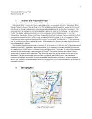
<strong>Vegetated</strong> <strong>Geogrids</strong>ApproachConstruction CostSoft Hard Low HighMaintenance CostAdaptabilityLow High Low HighDescriptionA vegetated geogrid is a soil wall thatcan be placed on a bank or shore that hasbeen severely eroded. The wall is madeup of successive soil lifts that areseparated by and wrapped in a syntheticcontrol fabric. This fabric serves to keepthe soil in place and branch cuttings areplaced between each layer. The livebranch cuttings serve several practicalpurposes. They act as a buffer to reducewave energy and shear stress at the faceof the wall. In addition, having thebranch cuttings present before thecompletion of the wall enables thevegetation to grow as rapidly aspossible. Finally, once established thebranches serve to bind the geogridstogether and provide a root structurebehind the wall, attaching it moresecurely to the shore. The toe of thestructure at the bank of the river orstream is further supported by layers ofrock on top of the soil lifts.Design and ConstructionInformation on the design of vegetatedgeogrids is sparse. <strong>Vegetated</strong> geogridsare mainly used on smaller rivers orstreams, and are designed to withstandmaximum current velocities of 14 feetper second, and shear stresses of up to 8pounds per square foot. The streambedneeds to be stable at the constructionlocation and all construction needs to beperformed during low tide.Figure 26. Typical <strong>Vegetated</strong> GeogridConstruction materials consist ofbranches (typically 0.5” to 2.5” indiameter - willow, dogwood, or woodyplants), rock fill (with diameters rangingfrom 4” - 9”), and an erosion controlfabric (synthetic polymer). Constructiontypically proceeds in a step-by-stepfashion with each successive layer beingbuilt upon the previous. The base isconstructed by excavating a two to threefoot trench into the streambed thatextends to the estimated scour depth.The trench is then filled up to the meanhigh tide water depth with rock, andwrapped in a control fabric. The firstgeogrid is constructed by filling the areawith soil and rock and wrapping it. Thefirst level of vegetation is then placed ontop of the first lift. Stakes or rebar arethen used to fix each layer of the geogridDRAFT
to the one beneath it. The geogridvegetationpattern is then continued tothe desired height, with each successivegeogrid shorter then the previous tocreate a slight slope. Once completed,soil is placed on top of the last geogridand the fabric of the geogrid is staked tothe shore. Grass and/or other vegetationcan be planted on the surface to helpanchor the structure. Vegetation canalso be planted on the ends to preventflanking.The cost of a vegetated geogrid ismoderate to high. Labor accounts forapproximately sixty-six percent of thetotal cost for a vegetative geogrid.Every linear foot of structure requiresroughly one man hour of labor. Materialcosts range from $13-30 per linear foot.<strong>Vegetated</strong> geogrids do need to bemonitored regularly in the early part oftheir development. It is important to seethat the branches have become rootedand are growing. Checking to see thatgullies do not form beneath the bed ofthe structure before the root system isestablished is vital to prevent failure.Once vegetation is established themaintenance costs are greatly decreased.AdaptabilityDo to their layered or terraced nature,vegetated geogrids can be extendedvertically with relative ease. The topmost layer can be excavtated andadditional geogrid-vegetation layers canbe added up to the desired height. Alimiting condition will occur howeverwhen the elevation of the land behindthe structure becomes equivalent to theelevation of the structure itself.Backfilling to increase the elevation ofthe land behind the structure may bepossible in these situations.Advantages<strong>Vegetated</strong> geogrids have manyadvantages over other engineered shoreprotection approaches, among them are:• They can have very steep slopes, sothey can be used on shores that dropoff suddenly or in areas where thebank cannot be modified to create agently slope.• They have a high aesthetic valuecompared to other shorelinehardening techniques and even othervegetated structures.• They can withstand relatively highcurrent velocities and shear stresses.• Vegetation can decrease the impactof the water on the surface of thestructure.• The structure will become morestable as it gets older and asvegetation grows.• They can be used to help restoreoutside bends that are extremelysusceptible to erosion.• They can capture sediment and helprebuild the toe of the stream bank.• They can improve the conditions forthe growth of native vegetation.DRAFTDisadvantages<strong>Vegetated</strong> geogrids have manydisadvantages compared to otherengineered shore protection approaches,among them are:• They have a relatively high cost.• The installation is complex andrequires heavy machinery.• Large amounts of soil and/or rockmust be available to fill the geogrids.Similar TechniquesAlternatives include: live crib walls.
Live Stakes / JointPlantingApproachConstruction CostSoft Hard Low HighMaintenance CostAdaptabilityLow High Low HighDescriptionJoint Planting consists of adding livestakes or vegetation into open spaces orjoints in an already existing rip rap orrock covered slope. Alternatively, thestakes can also be placed at the sametime as the rock reinforcement. Whenthe system of roots from the live stakesdevelops it creates a living root matbeneath the rocks, binding the soil andpreventing washout of the soil and finematerial.Figure 27: Typical joint planting.Design and ConstructionVery little information is available onthe design of joint plantings. Jointplantings are typically constructed inareas where a sloping rip-rap or rockrevetment either exists or is planned.Live stakes/joint planting should beconsidered only if the accompanyingstructure will be subject to minor waveaction. This method should be used onstreams with minimal flow fluctuations.The site should have a moderate slope,and sufficient lighting available for theplants to grow. Permissible shearstresses of 2.1 lb/sf - 3.1 lb/sf and flowvelocities of 3 ft/sec – 10 ft/sec are givenfor live willow stakes in Fischenrich(2001).Construction materials for a jointplanting project consist of 2” to 3”diameter live stakes (willow or otherwoody plants), and appropriately sizedrocks if an accompanying rock structureis to be built. The live stakes are placedperpendicular to the slope and tampedtwo thirds of their length into theground. A steel rod or hydraulic probemay be required to prepare the hole forthe planting. The joint plantings shouldbe left with their tips slightly protrudingfrom the surface of the rocks and placedin a random configuration. Afterconstruction there is typically littlemaintenance involved.DRAFTThe capitol cost of joint planting is lowcompared to other methods, particularlyif the rock covered slope already exists.Prices normally range from $1/sf - $5/sf.If additional site work is needed, thesecosts can rise to more than $35/sf.
AdaptabilityJoint plantings can be added to existingstructures as well as being incorporatedat the design stage. For this reason, aslong as there is room within thestructure, adding additional plantings toaccommodate for variations in waterlevel is expected to be straightforward.Similar TechniquesAlternatives include: branch packing,live fascines, brush mattresses.AdvantagesJoint plantings have many advantagesover other engineered shore protectionapproaches, among them are:• They can be installed rapidly if therock covered slope already exists.• They can help to dissipate waveenergy hitting the slope.• They reinforce the underlying soil asthey grow.• The roots of the live stakes improvethe drainage on slopes.• It is an economical method whensupplies are readily available.• The plantings act to trap soil on theshore, slow water velocities andimpede erosion.DisadvantagesJoint plantings have many disadvantagescompared to other engineered shoreprotection approaches, among them are:• They have minimal impact onwildlife and aquatic habitat sincethey must be constructed on existingrock slopes.• Only a small amount of additionalprotection is initially offered by thestakes.• Joint plantings are a complimentary,rather than a stand-alone shoreprotection approach.DRAFT
Brush MattressApproachConstruction CostSoft Hard Low HighMaintenance CostAdaptabilityLow High Low HighDescriptionA brush mattress incorporates livestakes, live fascines, and branch cuttingsto create one comprehensive protectivecover over a stream bank. This coverserves to slow the velocities of thestream as it runs against the shore and iscapable of capturing sediment duringflood conditions. The structure issupplemented with a rock base in orderto prevent scouring. The materials of themattress are held in place with wire, livestakes, and dead stout stakes. Oncedeveloped the mattress turns into astrong network of interlocking roots.conditions. For a brush mattress toproperly develop the site beingconsidered must be moist enough tosupport growth during the growingseason. Most woody plants howeverhave a limited tolerance for water thatcannot be exceeded. The amount ofavailable sunlight must also beconsidered depending on the type ofmaterial being used in the brushmattress. Willow and alder areparticularly sensitive to the amount ofsunlight. Soil conditions are importantbecause the roots must be able topenetrate the substrate.DRAFTFigure 29: Brush mattress installation.Figure 28: Brush mattress cross-section.Design and ConstructionImportant site considerations for a brushmattress project include moisture level,exposure to sunlight, and subsurfaceThe design of a brush mattress typicallyincorporates the followingconsiderations; the elevation of the bankwith respect to the level of water, thecurrent velocity and shear-stressthresholds (4 ft/sec and 0.4 lb/sf to 4.1lb/sf for a new placement and 12 ft/secand 3.9 lb/sf - 8.2 lb/sf for an establishedproject according to Fischenrich, 2001),
protection of the toe and flanks, properdrainage of the bank, and factorsimpacting plant growth. Slope is anoften overlooked factor that can beimportant because over-steep slopes caninhibit plant growth.Some of the typical steps in constructingbrush mattresses are as follows. Ifnecessary, the side slopes should begraded to a maximum steepness of 3:1 toensure vegetation takes hold. At thebase of the slope a trench needs to beexcavated for the structure toe. Stoutstakes can then be installed over the faceof the sloped area, with branches beingplaced in a layer over the top of theshoreline with the basal ends in thetrench. Wire is then used to tightly wrapone stout to the next. The stouts are thenstamped into the ground until the wiretightly secures the branches. Previouslyprepared live fascine bundles can then beinstalled in the trench over the basalends. Dead stout stakes can be driveninto the live fascines to secure them tothe ground. Finally, all the spaces in themattress are filled with the exception ofthe top surface which is left exposed.The cost of a brush mattress is heavilydependent on the local labor rates. A 10sf area of brush mattress can takeanywhere from a half hour to one and ahalf hours to construct. Constructioncosts for the dead stout stakes and thebinding can range from $4 to $7. Ageneral figure that has been used inprevious cost estimates is approximately$15/sf.The level of maintenance required willdepend on stream velocity, floodfrequency, and sediment load. Brushmattresses should be inspected at leastafter the predominant flood season.AdaptabilityBrush mattresses are not readilyadaptable given the level ofinterconnectedness within the structure.Unlike terraced or layered structures,modification requires substantially moreeffort than simply stacking on anotherlayer.AdvantagesBrush mattresses have many advantagesover other engineered shore protectionapproaches, among them are:• They provide the shoreline withimmediate protection and theirdurability increases with time.• They are effective on steep and fastflowing streams.• They work in concert with and canpromote the growth of nativevegetation.• They can servers as a habitat forbirds, small animals, and insects.DisadvantagesDRAFTBrush mattresses have manydisadvantages compared to otherengineered shore protection approaches,among them are:• A large amount of cuttings arerequired for construction.• Installation is extremely laborintensive.• They must be installed during thedormancy period of the live plantsbeing used.• The technique does not allowbranches to be buried deeply into thesoil.• As a living shoreline stabilizationapproach, specific conditions are
equired for the method to besuccessful.• If used on stream that has too muchsuspended sediment the structure canbe buried and become ineffective.Similar TechniquesAlternatives include: branch packing,live fascines, joint planting.DRAFT
Branch PackingApproachConstruction CostSoft Hard Low HighMaintenance CostAdaptabilityLow High Low HighDescriptionThe branch packing technique employsalternating layers of live branches andcompacted soil to repair gaps or holes onstream bank slopes. The branch packingapproach not only repairs missingsections of the shoreline but also aids inthe prevention of erosion and scouring.Branch packing can only be used at sitesthat have an area less than 4 feet deepand 4 feet wide that need to be filled andsupported. The technique is generallyineffective at sites with side slopes inexcess of 2:1.packing technique include: the size ofthe hole being filled, the steepness of theside slope, and the water level. Waterlevel must be considered as the ends ofthe plants must be able to reach thewater, while not receiving so muchwater as to exceed their flood tolerance.Figure 31: Shoreline stabilized with branchpacking.DRAFTBranch packing can employ a variety ofmaterials, including: live stakes, livefascines, live branches, dormant postplantings, dead stout stakes, string,smooth wire, wooden stakes, and rebar.Figure 30: Typical branch packing crosssection.Design and ConstructionSome of the important designconsiderations when applying the branchConstruction consists of driving woodenstakes vertically into the ground, thenplacing a four to six inch layer of livingbranches between the stakes, with theirgrowing tips orientated towards theslope. Construction should begin at thelowest point and proceed up the bank.Subsequent layers of live branches andsoil are then added until the structureconforms to the existing slope.
Detailed cost information was notavailable, however branch packing isexpected to be inexpensive compared toother shoreline stabilization alternativesbased on the minimal material and/orspecialized labor requirements.Similar TechniquesAlternatives include: joint planting, livefascines, brush mattresses.AdaptabilityThe branch packing approach can beextended vertically under potential sealevel rise scenarios; however the overallfragility of the structure will make ithighly susceptible to dislodgement underincreasing flows and/or wave activity.AdvantagesBranch packing has many advantagesover other engineered shore protectionapproaches, among them are:• It is an inexpensive method oferosion prevention.• Vegetation grows quickly and offersimmediate protection.• As the plants grow, the systembecomes more efficient in reducingrunoff and erosion.• The branches can encouragesediment deposition along the shore.DisadvantagesBranch packing has many disadvantagescompared to other engineered shoreprotection approaches, among them are:• They are ineffective in holes that arelarger than 4 feet deep by 4 feetwide.• Stream flow must be diverted ifbranch packing is being consideredat a site that was previously damagedby high velocity flow.• Scouring can occur if branch packingis not flush with the existing bank.DRAFT
Live FascinesApproachConstruction CostSoft Hard Low HighMaintenance CostAdaptabilityLow High Low HighDescriptionLive fascines are composed of longbundles of branch cuttings that havebeen bound together. Once bound, theyare placed in shallow cylindricaltrenches in rows along the shore. Thelive fascines are further supported bylive and dead stakes. Adding livefascines to a stream bank can reduceerosion and sliding of the slope.Figure 32: Typical live fascine cross-section.Live fascines must be placed on a bankwhich will keep the bundle wetthroughout the growing season, but notexceed the plant’s flood tolerance.Perennial, small to moderate streamswith a consistent water level are bestsuited for this type of stream bankstabilization project. Conditions at thesite must be such that the roots canpenetrate the earth, and reach the watertable. The amount of shade and type ofsoil at the site are also important.Figure 33: Live fascine stabilized slope.Design and ConstructionIn the design of a live fascine project,the most important factor is theconsideration of erosion at the toe andon the flanks of the installation. Watertable elevation is also important as thelive fascines must be able to accesswater during the growing season, yet notbe so close that they remain submergedfor long periods and die out. The type ofvegetation utilized to form the livefascines will depend on the siteconditions. Stability will be governedby stream flow conditions and shearstresses along the bank. According tothe information presented in Fischenrich(2001), live fascines can withstand shearstresses of between 1.25 lb/sf and 3.1lb/sf and velocities of between 6 ft/secand 8 ft/sec.DRAFT
Materials used to construct a live fascinebank stabilization project include: livebranch cuttings, live pegs, dead stakes,mulch materials, twine, and backfill.Construction typically involvespreparation of the live fascines andstakes prior to the commencement of thesite work. Site work will typicallyinvolve the excavation of one foot wideby one foot deep trenches along theslope beginning at the base. A series oftrenches will be excavated in rows alongthe entire bank. Long straw and/orannual grass can be planted between therows for further erosion prevention. Thebottom of the trenches should be layeredwith a geo-membrane or other erosioncontrol fabric. The fascines are thenplaced in the trench, with live stakesplaced on the downslope side of eachfascine and dead stakes driven directlythrough the fascine.The cost associated with a live fascineproject is low-moderately expensivewhen compared to other engineeredshore protection approaches. Materialcosts are generally low; however theapproach is fairly labor intensive.Once installed live fascines provideimmediate protection to the shore.Eighty percent of the live fascines mustsurvive for the project to be successful.The site should be examined after thefirst few floods or at least twice a year toensure the project is performing up toexpectations. The required maintenancewill depend on stream velocity, floodfrequency, and other parameters. Anyidentified flanking or undercuttingshould be repaired immediately toensure the continued stability of theproject.AdaptabilityLive fascines are adaptable from thestandpoint that they can always beextended up or down an existing slope toaccommodate fluctuating water levels.Dealing with die off at the toe of thestructure and possibly the associatedundermining and slumping howevercould prove difficult and costly. Livefascines also have a limited tolerance towaves and currents, so any increase ineither could damage an existinginstallation.AdvantagesLive fascines have many advantagesover other engineered shore protectionapproaches, among them are:• The approach does not cause a largeamount of site disturbance.• Once they are installed they provideimmediate protection.• Fascines trap soil and facilitatedrainage on the slope.• Fascines can enhance conditions forvegetation growth.• They retain a natural appearance andare typically considered aestheticallypleasing.DRAFTDisadvantagesLive fascines have many disadvantagescompared to other engineered shoreprotection approaches, among them are:• They are only effective on mildlysloping shallow shorelines.• They are only effective for smallerstreams.
Similar TechniquesAlternatives include: branch packing,joint planting, brush mattresses.DRAFT
Coconut Fiber RollsApproachConstruction CostSoft Hard Low HighMaintenance CostAdaptabilityLow High Low HighDescriptionCoconut fiber rolls are long, cylindricalstructures constructed from the fibers ofa coconut. They are most commonlyconstructed with diameters on the orderof 12 inches and lengths of between 18and 24 inches. The rolls are typicallyheld in place at the toe of a slope usingstakes. Coconut fiber rolls are used toboth prevent minor sliding on the shore,and to impede shoreline erosion.flow and wave energy are the twodominant destabilizing forces whichmust be considered.The first step in the construction processis the digging of a trench at the toe of theslope. The coconut fiber roll is thenplaced in the trench, with stakes utilizedto stabilize it. Back fill is added behindthe roll and vegetation is planted toprovide additional protection.DRAFTFigure 35: Close up of a coconut fiber roll.AdaptabilityFigure 34: Typical coconut fiber rollinstallation.Design and ConstructionCoconut fiber rolls are manufacturedoff-site and must be ordered prior to thecommencement of site preparation. Therolls are normally placed at the toe of theslope at the stream-forming flow stage.Shear stresses related to the dominantThe standard life of a coconut fiber rollis six to ten years. The roll is flexibleand can be formed to fit the curvature ofthe stream bank before placement. Onceplants start growing within the fiber rollthe structure can become rooted into thesoil. Once the roots take hold, thestructure can no longer be easilyrelocated.
AdvantagesCoconut fiber rolls have manyadvantages over other engineered shoreprotection approaches, among them are:• They are flexible and can mold to thecurvature of the stream bank.• They reinforce the stream bankwithout disturbing the existinghabitat.• Plant growth can develop in the fiberroll andDRAFTthe structure can becomerooted into the system.• Material is natural and eventuallybiodegrades.DisadvantagesCoconut fiber rolls have manydisadvantages compared to otherengineered shore protection approaches,among them are:• They are susceptible to puncture bydebris and/or ice flows.• The rolls are manufactured and canbe expensive• They can not be used at sites whereflow velocities are high.Similar TechniquesAlternatives include: dormant postplanting, jacks field.
Reed ClumpsApproachConstruction CostSoft Hard Low HighMaintenance CostAdaptabilityLow High Low HighDescriptionReed clumps are a natural shorelineerosion control methodology, frequentlyused to patch erosional hot spots. Thetechnique involves placing individuallywrapped root divisions in an excavatedtrench, then anchoring the system withstakes. The root mat which developsstabilizes the soil by reinforcing the soilmatrix, while at the same time removingexcess moisture. Like many of thenatural shore protection approaches, rootwads are dependent upon the naturalgrowing conditions (light, water, etc.)for their establishment and survival.Typical species used in reed clumpshoreline stabilization projects includearrowhead, cattail, and water iris.the design of reed clump shorelinestabilization projects.Reed clumps typically range in diameterfrom 3 inches, up to 1 foot and can beprefabricated. The fabrication processconsists of wrapping the individualclumps in a natural geotextile materialand securing them with twine. Theclumps can either be formed into rolls orplaced directly in an excavated,geotextile fabric lined trench. Theclumps are typically placed 12 to 18inches apart, with soil being used to fillthe remainder of the trench. Dead stoutstakes are used to secure the installationto the bank until the root systemdevelops.DRAFTFigure 36: Typical reed clump project crosssection(U.S. Department of Agriculture,2006).Design and ConstructionThere are few design guidelines outsideof maximum shear stress limits to aid inFigure 37: Close up of a reed clump shorelinestabilization project (Robbin B. Sotir &Associates photo).Reed clumps are inexpensive both interms of material and labor cost.Maintenance is typically not required;however the relative simplicity of the
approach makes replacing entire sectionspossible if required.AdaptabilityReed clumps are generally considered ashort term, temporary shore protectionalternative. Because of the relativelylow cost of materials and installation, theassumption is that an entire project canbe replaced rapidly if required.AdvantagesReed clumps have many advantagesover other engineered shore protectionapproaches, among them are:• They are flexible and can mold to thecurvature of the stream bank.• They promote a “green” shoreline,including colonization by naturalvegetation.• Reed clumps can be installed quicklyand economically.• They tend to accumulate sedimentand strengthen with age.DisadvantagesReed clumps have many disadvantagescompared to other engineered shoreprotection approaches, among them are:• They are susceptible to damage bywaves, moderate currents, and debrisand/or ice flows.• Frequently additional protection isrequired while the root systemdevelops.Similar TechniquesAlternatives include: live fascines,branch packing, brush mattresses.DRAFT
Dormant Post PlantingApproachConstruction CostSoft Hard Low HighMaintenance CostAdaptabilityLow High Low HighDescriptionDormant post planting refers to thetechnique of placing medium sized treesinto the slope of a stream bank in arectangular or triangular pattern. Therethey form a permeable barrier on theshore, working to slow the flow in thestream and retain the soil on the shore.Once the plantings develop they providefurther protection against erosion.Figure 38: Typical cross-section of a dormantpost planting project.Design and Constructionnumber of rows of plantings desired, theconfiguration and placement of theplantings, and if extra vegetation ispreferred. Typically, the length anddiameter of the plantings will bespecified. Stream curvature and streamvelocity, will have the most significantimpact on the success of a project.DRAFTDesign and construction of a dormantpost planting shoreline stabilizationproject is straightforward. One of theprimary considerations when designingthe project is water level, because theends of the plantings need to have accessto the water. The rest of the designprocess consists of simply choosing theFigure 39: Constructed dormant post plantingproject.Once an appropriate plant species ischosen, they are cut into seven to ninefoot long pieces, and their ends aretapered for easy insertion into the soil.The posts are installed into the bank
above the normal waterline, with half totwo-thirds of their length being buried.Two to several rows of posts are plantedin a rectangular or triangular formation,with vegetation added post constructionto further prevent slope erosion.• It has a limited range of applicabilitybased on wave and stream flowconditions.Similar TechniquesDormant post planting is an inexpensivemethod for controlling erosion alongstream banks. The cost per post rangesfrom $2 to $3. Typically, a laborer cancomplete between 0.2 m 2 and 1 m 2 perhour. Local labor rates can be used toestimate labor costs.AdaptabilityThe dormant post planting approach isfairly adaptable. New posts andplantings can be added at any time.Posts that are ineffective should beremoved or cut off near the bed toprevent them from becoming a hazard.AdvantagesDormant post planting has manyadvantages over other engineered shoreprotection approaches, among them are:• Natural vegetation is an integral partof the approach.• Natural methods are used to slow theflow of the stream.• Sediment may be accumulated by theplantings.DisadvantagesDormant post planting has manydisadvantages compared to otherengineered shore protection approaches,among them are:• It is susceptible to damage byice/debris floes.Alternatives include: wave screens, sills,breakwaters.DRAFT
Soil BioengineeringApproachConstruction CostSoft Hard Low HighMaintenance CostAdaptabilityLow High Low HighDescriptionSoil bioengineering is a generic term thatlike “Living Shorelines” can be used torefer to a variety of the approachesdiscussed within this document. Soilbioengineering refers to the concept ofutilizing vegetation to stabilize the soilalong the banks of a stream. Thevegetation itself provides immediateprotection and as the root systemsdevelop, they bind the soil more tightlycreating a resistance to sliding or shear.Soil bioengineering projects can alsoinclude structural components ifadditional bank protection is required.Examples of soil bioengineeringapproaches discussed in more detail inthis document include: brush mattresses,live stakes, joint plantings, vegetatedgeogrids, branchpacking, and livefascines.Design and ConstructionThe applicability of the soilbioengineering approach will depend onthe intensity of the erosional forces.Live vegetation has a limited ability towithstand both current induced shearstresses (Fischenrich, 2001 suggestsvelocities of
• Soil bioengineering projects are idealfrom both an aesthetic as well asecological point of view.DisadvantagesSoil bioengineering has manydisadvantages compared to otherengineered shore protection approaches,among them are:• Specific growing conditions arerequired.• They technique has a limited rangeof applicability due to the inability ofmost plants to withstand strong flowsand wave action.Similar TechniquesAlternatives include: brush mattresses,live stakes, joint plantings, vegetatedgeogrids, branchpacking, and livefascines.DRAFT
Living ShorelinesApproachConstruction CostSoft Hard Low HighMaintenance CostAdaptabilityLow High Low HighDescriptionLiving shorelines is being included as aseparate category with the realizationthat the term “living shoreline” is oftenused broadly to represent a system ofprotection that incorporates many of theindividual approaches identified in thisdocument. Living shorelines involvebank stabilization and habitat restorationto reduce shoreline erosion, and maintaincoastal and estuarine processes throughnatural approaches. Living shorelinesare considered more of a “soft” approachto shoreline stabilization, because of theuse of non-structural, natural and oftenbiodegradable techniques. The use ofvegetation often plays a significant rolein developing a living shoreline.Vegetation helps to anchor down thesoil, preventing erosion of the shoreline,while at the same time trapping newsediment. Also, the vegetation providesshelter and habitats for wildlife livingalong the shoreline. Vegetation can alsoacts as a natural filter for removingpesticides and fertilizers from runoff,and help to dissipate wave energy.Aquatic vegetation can also be used toincrease the bottom roughness andhence, dissipate wave and current energyalong the shoreline. Natural reefs suchas oyster reefs can also be used todissipate energy, and create submergedhabitats. Other materials frequently usedalong living shorelines include sand fill,and biodegradable materials such asnatural fiber “bio-logs” and organicmatting. Along some higher energyshorelines, a hybrid of solutions may beimplemented, where low-profile rockstructures may be used to dissipateenergy.Figure 40: Typical cross-section of a livingshoreline.Design and ConstructionDRAFTThe first step towards designing a livingshoreline is conducting a site analysis todetermine which techniques areappropriate for the site in question.Erosion rates must be determined, andlocal species must be documented forhabitat recreation. Post-construction,monitoring and maintenance are requiredto document the success of habitatcreation and to ensure the project meetsits shoreline stabilization objectives.The design and construction costs forliving shorelines are very muchdependent on location, and type oftechnique being implemented
(vegetation, oyster reefs, etc). However,living shoreline techniques are often lessexpensive than the more traditional“hard” engineering options, such asriprap or bulkheads. Living shorelinesdo typically require a long terminvestment, as maintenance andmonitoring are required postconstruction,yet these costs will lessenas the shoreline becomes more stableand strengthens.AdaptabilityLiving shorelines can adapt to stressors,such as sea level rise and change instorm intensity. As sea level rises, andincreased storm intensity causes moredamage to the shorelines, the shorelinesmust be maintained and restored byplanting more vegetation to preservewildlife habitats. Also, debris may needto be removed from the shoreline tomaintain the natural scape of theshoreline.AdvantagesLiving shorelines have many advantagesover other engineered shore protectionapproaches, among them are:• They reduce the negative effect of“hard” engineering structures.• They create habitats for vulnerableshoreline species.• They help maintain good waterquality.• They can be less expensive in lowenergy areas.DisadvantagesLiving shorelines have manydisadvantages compared to otherengineered shore protection approaches,among them are:• Seasonality can have a significantimpact on vegetation growth.• Continuous monitoring andmaintenance may be required todocument success.• Some techniques may be of limitedusefulness in high energy conditions.Similar TechniquesAlternatives include: living breakwaters,sills, live fascines, live stakes, brushmattresses.DRAFT
GroinsApproachConstruction CostSoft Hard Low HighMaintenance CostAdaptabilityLow High Low HighDescriptionGroins are fingerlike shaped barriers thatproject from the shoreline disruptingflows and transport occurring parallel toshore. Groins (also referred to asgroynes, spur dykes or wing dykes) havebeen used for centuries along shorelinesto protect the bank and control channelmeanders. Typically constructed inseries, groins can be built perpendicularto the shoreline or angled eitherupstream or downstream, depending onthe objective. Groins angled upstreamor perpendicular to the flow are referredto as “deflecting” or “repelling”structures, as they deflect the currentaway from the bank. Groins angleddownstream have the opposite effect,scouring areas close to the bank andmaintaining a deep current close toshore. These structures are known as“attracting” groins. Typical angles ofinclination are between 10° & 30° withrespect to the bank. Depending on theapplication, the structures may either bepermeable or impermeable, and aretypically constructed of solid earth,timber, brush, branches, rocks, or somecombination thereof.Groins function in two ways. First byslowing the current in the immediatevicinity of the bank, the erosionalpressure is reduced. Second, as aconsequence of the flow slowing,suspended material falls out creating anearshore platform or build up ofsediment. This platform can have theadded benefit that it acts as a buffer tooncoming waves, causing the energy todissipate on the platform before reachingthe shoreline. In regions, such as theHudson, where flow reversals arecommon, angled structures will act asboth deflecting and attracting structuresdepending on the stage of the tide.Groins must be able to extend farenough into the water to catch thedesired amount of sand.DRAFTFigure 41: Typical groin field.Design and ConstructionWhen designing a groin; the dimensions,profile, spacing, active forces and thesizes of the structural members must allbe considered. As discussed in theprevious section groins are typicallyconstructed in groups. Depending on theapplication, the spacing betweenindividual groins is generally on the
order of 1 – 2.5 times the length of theindividual groins. The groins should berooted into the shore to prevent flankingduring storms or flood conditions. Sideslopes on river groin structures aretypically between 2 and 3 (horizontal) to1 (vertical).• Some people may consider theresulting shoreline planform aneyesore.• Groins disrupts the natural currentsand long shore sediment transport.• Groins are susceptible to damagefrom ice and/or debris flows.In order for a groin to remain effective,it must be monitored and if necessarymaintained. When designed andconstructed correctly, maintenance ongroins is typically minimal; however ifimproperly designed, maintenanceactivities can range from thereplacement of individual pieces orstructural members to, in rare cases, thereplacement of the entire structure.AdaptabilityGroins are fairly adaptable in that raisingthe crest elevation, extending thestructure, or reinforcing weak sectionscan all be done with relative ease.AdvantagesGroins have many advantages over otherengineered shore protection approaches,among them are:• They have minimal impact on thenatural bank habitat and can evencreate new habitat due to thereduction of currents.• The collected sand preventsshoreline erosion and maintains thebeach for recreational purposes.DisadvantagesGroins have many disadvantagescompared to other engineered shoreprotection approaches, among them are:Similar TechniquesAlternatives may include: stream barbs.DRAFT
Stream BarbsApproachConstruction CostSoft Hard Low HighMaintenance CostAdaptabilityLow High Low HighDescriptionStream barbs are similar to groins andfunction in much the same way; howeverthey tend to be lower in relief and lessobtrusive. Stream barbs are constructedas low rock sills that project out from astream bank and serve to redirect flowaway from an eroding shoreline. Similarto groins, they are normally placed ingroups of three or more and run parallelto each other.Figure 42: Overhead view of a stream barbinstallation.Design and ConstructionSome of the important factors that needto be taken into consideration whendesigning a stream barb field are thelength, width, and height of theindividual barbs, the spacing betweenbarbs, and the angle between the barbsand the upstream bank.Figure 43: Field installation of stream barbs.Stream barb construction typicallybegins at the shore and continues streamward.Typical stream barb dimensionsare 2 feet high by 8 to 10 feet wide.When installed in series, spacingbetween the barbs generally ranges from4 to 5 times the length of the individualbarbs. Common angles of inclinationwith respect to the upstream bank arebetween 50 and 80 degrees.DRAFTDue to their more modest size, streambarbs are generally cheaper to constructthan groins. In addition to the lowermaterial costs associated with usingsmaller stones, labor costs are alsoreduced, due to less reliance on heavymachinery.AdaptabilitySimilar to groins, stream barbs are fairlyadaptable in that the elevation or lateralextent of the structure can be modified
with relative ease. In additionreinforcement through the addition oflarger armor stone and/or theintroduction of additional toe protectionmeasures is relatively straightforward.AdvantagesStream barbs have many advantagesover other engineered shore protectionapproaches, among them are:• They can be more cost-effective andless intrusive than groins.• They can improve fish habitat.• They are readily applicable alongsideother soil bioengineering techniques.• Stream barbs can trap sediment.DisadvantagesStream barbs have many disadvantagescompared to other engineered shoreprotection approaches, among them are:• Their applicability is limited tosmaller streams.• Although cheaper than groins,stream barbs can still be relativelyexpensive compared to many of thesoft techniques.• The resulting jagged shoreline edgemay not be acceptable from anaesthetic stand point.Similar TechniquesAlternatives may include: groins.DRAFT
Wave ScreensApproachConstruction CostSoft Hard Low HighMaintenance CostAdaptabilityLow High Low HighDescriptionWave screens are structures placedoffshore with the primary purpose ofreducing wave energy in their lee;however oriented perpendicular to thedominant flow direction(s), they can alsobe used to reduce current velocities.Wave screens, or permeable pilebreakwaters, consist of a combination ofhorizontal, vertical, and/or diagonal slatsaffixed to rigid vertical and/or horizontalsupports. Energy dissipation at a wavescreen is primarily a function of theporosity of the structure, which isgoverned by the spacing of the slats.The permeability of the screens allowsthe structure to attenuate waves, whileminimizing any negative environmentalimpacts.dominant wave direction; however if thedesign calls for the structures to alsoreduce current energy, the design may beoptimized such that the structures maybe angled relative to the dominant waveand current conditions. In this case caremust be taken to ensure that navigationis not impacted by the structure.Design and ConstructionThe design of wave screens will varydepending on site conditions. Theperformance of a wave screen isgoverned by the amount of wave energywhich is transmitted through thestructure. Typically, a transmissioncoefficient, k t , which is defined as theratio of the transmitted wave height tothe incident wave height is used toevaluate the effectiveness of a givenstructure. A value of k t = 1 indicatescomplete wave transmission (andDRAFTtherefore an ineffective structure) and avalue of k t = 0 indicates completedissipation (or reflection). Put anotherway, the percent reduction in waveenergy behind a wave screen is given by:Figure 44: Typical wave screen cross-section.Wave screens are predominantlyconstructed perpendicular to theE⎛ H ⎞1 ⎟x100⎝ ⎠2t% r= ⎜ −2HiWhere H t is the transmitted wave heightand H i is the incident wave height.Wave screens can be constructed ofsteel, concrete, or timber, although
timber is most common. Constructionconsists of driving piles into the sea bed,then affixing a horizontal plate, or cap,and the required slats. Embedment ofthe support structure may involvesignificant effort depending on thesubsurface conditions. The screensthemselves can often be prefabricatedoff-site, shipped, and installed withminimal effort.Compared to the other stream bankstabilization approaches in terms of cost,wave screens are somewhere in themiddle. Wave screens are moreexpensive than most of the soft shorelinestabilization approaches, but lessexpensive than many of the hardapproaches. Costs are typically$1,500/lf - $2,000/lf.The costs associated with the operationand maintenance of wave screenstructures is typically small. Unless thesupport structure itself is damaged byfloating debris, ice, or wayward ships,maintenance is typically limited to thereplacement of slats which have becomedamaged. Under most conditions, astructure life of up to 20 years ispossible.AdaptabilityWave screens are fairly adaptablestructures. The degree of energydissipation can be modified relativelyeasily by changing the porosity of thestructure through the addition orsubtraction of slats. In addition the wavescreen structure itself can be raised orlowered by altering the way in which itis fixed to the support structure. Addingand/or removing support structures;however will require more effort.AdvantagesWave screens have many advantagesover other engineered shore protectionapproaches, among them are:• The slotted design reduces waveand/or current energy while stillallowing for an exchange of water.• Repair costs are typically minimal.• The calm region in the lee of a wavescreen may serve as useful habitatand encourage sediment deposition.• They are durable structures that haveminimal operation and maintenancecosts.DisadvantagesWave screens have many disadvantagescompared to other engineered shoreprotection approaches, among them are:• They care susceptible to damage byice floes.• They have higher design andconstruction costs than most of thesoft approaches.• Their effectiveness on shorelineswith strong currents is not welldocumented.DRAFTSimilar TechniquesAlternatives include: breakwaters,floating breakwaters, living breakwaters,sills, dormant post plantings.
BreakwaterApproachConstruction CostSoft Hard Low HighMaintenance CostAdaptabilityLow High Low HighDescriptionBreakwaters are shore parallel structuresthat function by reducing the amount ofwave energy reaching the area behindthem. This is achieved through acombination of dissipation, reflectionand even refraction of the incomingwave field. Sediment deposition in thelee of a breakwater due to a combinationof the calm waters being more favorablefor sedimentation, and the fact thatrefraction tends to cause a convergenceof wave energy and sediment transport isoften observed.Breakwaters along sheltered shorelinestend to be much smaller than those alongopen coasts. Typical constructionmaterials include rubble, concrete, andwood, although recently, livingorganisms such as oysters and musselshave been utilized to create livingbreakwaters (see separate section).Breakwaters may be shore attached, orstand alone and can either be continuousor segmented.Design and ConstructionBreakwater design consists ofdetermining the stable armor unit size, aswell as defining the structure geometry.Armor stone is typically selected byapplying a formula such as the Hudsonformula (see Revtements). Critical areaswhere scour and flanking are likely tooccur may require additional designconsideration. Factors such as limitingwave run-up, overtopping, andreflections will influence structuregeometry. Geometry is also influencedby cost considerations, where steeperside slopes can lead to substantialmaterials savings.Breakwater construction requires a solidbase to prevent settlement. Subsurfaceconditions should be checked and ifnecessary supplementary measuresemployed to ensure a solid foundation.A filter fabric is typically used to limitscour and prevent the washout of finematerial from beneath the structure. Agravel layer is placed on top of the filterlayer building up the core of thestructure. Along sheltered shorelines asingle or double layer of armor units isplaced over the base layer(s) to provideresistance to the dominant wave andcurrent forces.DRAFTBreakwaters tend to be rather expensivewhen compared to other shorelinestabilization techniques, due to the largerstone sizes required and the cost totransport and install them. On the otherhand however, breakwaters also requireminimal maintenance and can functionsafely even after one or more armorunits has been shifted.
AdaptabilityBreakwaters are typically substantialstructures with a limited capacity toadapt to a changing environment. Whilethe displacement of individual armorunits does not imply impending failure,it may result in a loss of effectiveness.Alternatives include: wave screens,floating breakwaters, living breakwaters,sills, dormant post plantings.AdvantagesBreakwaters have many advantages overother engineered shore protectionapproaches, among them are:• They can be designed to withstandsignificant wave activity.• They can generally sustain minordamage and remain effective.• Breakwaters do not interrupt thenatural shoreline, and frequentlycreate aquatic habitat.• Maintenance requirements areminimal and structures are robust.DisadvantagesBreakwaters have many disadvantagescompared to other engineered shoreprotection approaches, among them are:• They can be expensive compared toother shoreline stabilizationtechniques.• There is limited research on theimpacts of breakwaters on vegetatedshorelines.• Structures are subject to settling,scour and flanking.• Since they are constructed somedistance from the shoreline they maypose a hazard to navigation.Similar TechniquesDRAFT
Floating BreakwaterApproachConstruction CostSoft Hard Low HighMaintenance CostAdaptabilityLow High Low HighDescriptionA floating breakwater is a special type ofbreakwater that floats within the watercolumn, but performs the same functionas a traditional breakwater. Floatingbreakwaters are typically shore parallelstructures (or more accurately waveperpendicular structures) that protect theshoreline by reducing the amount ofwave energy in the shadow zone createdbetween it and the shoreline. On opencoasts, sediment often accumulateswithin this low energy region.Figure 45: Floating breakwater installation.Floating breakwaters can and have beenconstructed from many different types ofbuoyant materials including tires, logs,timber, hollow concrete modules, andheavy duty plastic. Floating breakwatersmust be securely anchored to the bottomto withstand the often substantial waveinduced forces.Design and ConstructionThere are several important parameterswhich must be set during the design of afloating breakwater. The length andwidth of the structure must bedetermined along with its free board(crest elevation above the water line), itsdistance offshore and the correspondingwater depth. All of these parametersplay a role in determining the degree ofwave energy reduction behind thestructure. This in turn will determine theimpact on the shoreline behind thestructure. A second importantconsideration is the way in which thebreakwater will be fixed to the bottom.Waves and currents can inducesignificant forces therefore the anchoringmechanism must be robust.DRAFTFloating breakwaters vary in costdepending on the type of material usedin construction. Proprietary units exist,however readily available material (tires,logs, etc) can also be used, to reducecost.Once set in place, floating breakwatersare typically maintenance free.Inspections should be performed aftermajor storms to ensure the structure isstill securely anchored, and to clear anyaccumulated debris.
AdaptabilityAs a floating structure, a floatingbreakwater can readily adapt to changingwater levels. It may be necessary toadjust the tension in the anchoringmechanism; however the structure itselfshould be capable of being “tuned” toobtain the desired wave height reduction.AdvantagesFloating breakwaters have manyadvantages over other engineered shoreprotection approaches, among them are:• They can be constructed from manydifferent types of materials.• They can be used where the water istoo deep for fixed breakwaters.• Since the do not extend to thebottom, water exchange is not aconcern.• They can be used at sites that have alarge tidal range, without thestructure being submerged.DisadvantagesFloating breakwaters have manydisadvantages compared to otherengineered shore protection approaches,among them are:• They are only effective againstwaves whose period is shorter thanfive seconds. Fortunately, wavesalong sheltered shorelines typicallyfall into this category.• They can be an eyesore.• Floating debris can collect along thestructures requiring periodicmaintenance and removal.• They require more maintenance thanfixed breakwaters.• If sediment accumulates behind thesestructures, down drift erosion mayoccur.• Heavy construction equipment isnecessary for construction.Similar TechniquesAlternatives include: living reefbreakwaters, breakwaters, sills, wavescreens, dormant post plantings.DRAFT
Living Reef BreakwaterApproachConstruction CostSoft Hard Low HighMaintenance CostAdaptabilityLow High Low HighDescriptionRecently, living breakwaters have comeinto vogue for use as shore protectionalong sheltered shorelines. Thesesubmerged aquatic habitats are mostcommon in the southern United Statesand functionally work in a similarmanner to constructed breakwaters. Inthe northeast, living breakwaters aretypically constructed by using oysters ormussels as the dominant species. Bothspecies can grow rapidly near estuarineriver mouths and in near shore areas.Many of the natural beds have long sincedisappeared, so current projects typicallybegin in a controlled environment wherethe beds are recreated. Larvae of thespecies naturally seek out a hard surfaceto settle upon, and thus develop on theshells of mature oysters and/or mussels.Over time as generations of the speciescontinue to grow large reef structures areformed. As they develop, these reefsserve as critical aquatic habitat. Fullydeveloped, the reefs act as a naturalbreakwater by dissipating the incidentwave energy, and creating areas of calmwater.Design and ConstructionSince the technique is so new, and relieson natural rather than man madeprocesses, limited guidance was found inthe literature. An important factor in siteselection is water quality. Both oysterand mussel reefs require specificconditions in order for the species tothrive and become self sustaining.Figure 46: Established oyster reef.DRAFTFigure 47: Established mussel reef.Construction typically consists of “jumpstarting” the growth of the reef byproviding a suitable substrate for newoysters and mussels to colonize. Oncethe process takes hold, nature takes overand the reef can be allowed to developnaturally.
AdaptabilityLiving breakwaters have a limitedcapacity to adapt to changing conditionsbecause of the specific water qualityparameters required to sustain thespecies involved. Unlike man madestructures, living reefs are sensitive to anumber of water quality parameters suchas water temperature, salinity, etc.AdvantagesLiving reef breakwaters have manyadvantages over other engineered shoreprotection approaches, among them are:• They serve important habitatfunctions.• They work with nature instead ofagainst it.DisadvantagesLiving reef breakwaters have manydisadvantages compared to otherengineered shore protection approaches,among them are:• They are susceptible to damage bydebris and/or ice flows.• They are less resistant to changingconditions than man made structures.Similar TechniquesAlternatives include: floatingbreakwaters, breakwaters, sills.DRAFT
SillsApproachConstruction CostSoft Hard Low HighMaintenance CostAdaptabilityLow High Low HighDescriptionSills are low elevation stone structuresthat are placed in the water parallel tothe shoreline. Similar in function to abreakwater, sills help reduce waveenergy and erosion on the shore orstream bank. The calm area that isgenerated behind a sill allows sand andsediment to build up between thestructure and the shoreline, ultimatelyraising the elevation of the stream bed(perched beach). In some cases the areabetween the sill and the shoreline isprefilled to hasten the development of aperched beach. The resulting perchedbeach and sill structure causes waves tobreak farther away from the shore anddissipate some of their energy beforereaching the eroding shoreline.reducing the overtopping which isimportant for water exchange. Lowercrest heights also make accessing deeperwater easier for wildlife. Whensubmerged, sills disappear into thelandscape, but may represent anavigation hazard. Stone size, sillplacement and geometry, are allgoverned by the desired wave heightreduction and shoreline profile behindthe structure.DRAFTFigure 49: Sill and marsh shore protectionproject.AdaptabilityFigure 48: Typical sill/perched beach crosssection.Design and ConstructionBecause smaller stone sizes and a lessexacting profile are required whenbuilding a sill, modifying the structureonce in place will be easier than forlarger more complicated structures.Sills can either be placed above or belowthe mean water line. Increasing the sillheight can result in significantly moreprotection, but at the expense of
AdvantagesSills have many advantages over otherengineered shore protection approaches,among them are:• The shoreline retains many of itsnatural characteristics.• Sills can be submerged and thereforedo not affect the view of the streambank.• Sills can be constructed from a rangeof different materials, depending onwhat is locally available.• Once a sill is constructed a marsh orvegetation can be added between thestructure and the shoreline, furtherincreasing its value.DisadvantagesSills have many disadvantages comparedto other engineered shore protectionapproaches, among them are:• They can produce dangerous slopesand abrupt changes in depth.• If sediment and sand is trappedbehind the sill, erosion can result ondowndrift shorelines.• They are susceptible to damage byice and/or debris floes.• When submerged, they can representa navigation hazard.Similar TechniquesAlternatives may include: breakwaters,floating breakwaters, living breakwaters,wave screens.DRAFT
Artificial VegetationApproachConstruction CostSoft Hard Low HighMaintenance CostAdaptabilityLow High Low HighDescriptionArtificial vegetation (such as artificialseagrass) can be installed on river beds andflood plains to reduce wave and currentenergy. Artificial vegetation can also beused to trap sediment in areas where livevegetation may not be prone to grow.Artificial vegetation is typically made ofclosed-cell foamed polypropylene, and canbe installed in strips, with an ironreinforcing rod mesh to create an artificialseagrass mat lying along the seabed. Thepolypropylene strips, which float freelyand are in constant motion, act to slow thelocal currents and dissipate wave energy.At the same time, suspended sediment fallsout of the water column, raising the localbed elevation.Design and ConstructionDetailed design and constructioninformation for artificial vegetationshoreline stabilization projects is sparse.Projects are designed based on theobjective of dissipating wave and currentenergy in their lee. In 1990, artificialseagrass mats were installed at a projectsite in Australia to stabilize a shipwreckand trap sediment within the area. Thedesign called for twenty-four strips (each1.6 cm wide by either 90 cm, 120 cm or150 cm long), creating an artificial seagrass mat. Each mat was weighed downby railway iron, and a total of 42 matswere deployed. The approximate cost ofthe project was A$100,000.DRAFTFigure 50: Installation and subsequent sedimenttrapping by artificial seagrass mats in Australia.Historically, artificial vegetation projectsconstructed in high energy environmentshave been plagued by an inability towithstand the destructive forces. As aresult individual stripes and even entiremats have been washed away. As matsbecome torn, they lose their effectiveness
in trapping sediments, and may need to berepaired or replaced.AdaptabilityAlternatives include: natural vegetation,living breakwaters, floating breakwaters,wave screens.Once installed, artificial vegetation matscan be moved, rearranged, or removedrelatively easily. As sea levels rise,increased water depths may begin to limitthe effectiveness of the mats.AdvantagesArtificial vegetation has many advantagesover other engineered shore protectionapproaches, among them are:• It can serve as habitat for aquaticspecies.• It is easy and cost effective to install.• It can be used in waters incapable ofsupporting natural vegetation.• It protects the bank from erosion due towaves and currents.• Artificial vegetation remainssubmerged and preserves the naturalvistas.DisadvantagesArtificial vegetation has manydisadvantages compared to otherengineered shore protection approaches,among them are:• Applications are limited to low energyenvironments.• Damaged installations may wash up onshorelines and become a hazard.• They are susceptible to damage fromice and debris flows.• It is not adaptable for sea level rise.• It carries with it potentially significantmaintenance costs.Similar TechniquesDRAFT
SummaryBulkheadGabionsRevetmentsRootwad RevetmentTree RevetmentRip-rapJack FieldsGreen WallsLive Crib WallsLeveesDune Core<strong>Vegetated</strong> GeogridLive StakeBrush MattressBranch PackingLive FascinesCoconut Fiber RollsReed ClumpsDormant Post PlantingSoil BioengineeringApproachConstructionCostMaintenanceCostAdaptabilitySoft Hard Low High Low High Low HighSoft Hard Low High Low High Low HighSoft Hard Low High Low High Low HighSoft Hard Low High Low High Low HighSoft Hard Low High Low High Low HighSoft Hard Low High Low High Low HighSoft Hard Low High Low High Low HighSoft Hard Low High Low High Low HighSoft Hard Low High Low High Low HighSoft Hard Low High Low High Low HighSoft Hard Low High Low High Low HighDRAFTSoft Hard Low High Low High Low HighSoft Hard Low High Low High Low HighSoft Hard Low High Low High Low HighSoft Hard Low High Low High Low HighSoft Hard Low High Low High Low HighSoft Hard Low High Low High Low HighSoft Hard Low High Low High Low HighSoft Hard Low High Low High Low High
Living ShorelinesGroinsStream BarbsWave ScreensBreakwaterFloating BreakwaterLiving Reef BreakwaterSillsArtificial VegetationSoft Hard Low High Low High Low HighSoft Hard Low High Low High Low HighSoft Hard Low High Low High Low HighSoft Hard Low High Low High Low HighSoft Hard Low High Low High Low HighSoft Hard Low High Low High Low HighSoft Hard Low High Low High Low HighSoft Hard Low High Low High Low HighSoft Hard Low High Low High Low HighSoft Hard Low High Low High Low HighDRAFT
Glossary of TermsArtificial Dune Cores – Artificial reinforcement added to the core of dunes or slopedbanks to increase stability during erosional events. Typically, constructed of sandfilled geotubes, artificial dune cores remain hidden within the dune/bank onlybecoming “active” during extreme events.Artificial Vegetation - Artificial vegetation works identically to natural vegetation bydecreasing wave/current energy at the shoreline, reducing erosional pressure, andencouraging sediment deposition. Unlike natural vegetation, artificial vegetation canbe used in most areas, regardless of water quality/growth conditions.Bio/Green Walls - Walls or barriers that incorporate living plants or stakes into theirdesign. This term is used to refer to a collection of approaches, all of which attempt tosoften a traditionally hard edge through the introduction of ecologically friendlymodifications.Bulkhead – Traditionally, the most common shoreline hardening technique used toprotect vulnerable and eroding shorelines. Used at the base of bluffs or steepshorelines, bulkheads are vertical walls which prevent the loss of soil and the furthererosion of the shore.Branch Packing - Branch packing consists of segments of compacted back fill separatedby layers of live branches. This approach is a relatively inexpensive technique used tofill in missing areas of the shoreline, which also provides a succession of barriers toprevent further erosion and scouring.Breakwater - A breakwater is a structure that is built within a water body to reduce waveenergy and erosion in its lee. Types include rubble mound breakwaters, floatingbreakwaters, and living breakwaters.DRAFTBrush Layering - Brush layering consists of placing branch cuttings along a slopedshoreline to serve as a covering and protection against erosion. Brush layering mayalso stabilize the shoreline by capturing sediment.Brush Mattress - A brush mattress is a combination of live stakes, live fascines, andbranch cuttings that form a protective cover on an eroding shoreline that acts to protectthe shoreline against oncoming waves, capture sediment during floods, and enhancehabitat for vegetation.Coconut Fiber Rolls - Coconut fiber rolls are long cylindrical structures composed ofcoconut husks that are laid parallel to the shore. These structures are intended to helpprevent minor slides while encouraging sediment deposition and plant growth.Dormant Post Planting - Dormant post are installed into an eroded bank at or above thewaterline. Rootable vegetative material is added to form a permeable revetment alongthe shoreline.
Gabions - Gabions are wire mesh containers that can be used to form retaining walls, seawalls, channel linings or revetments. The containers are generally filled with cobblesor crushed rock and stacked to form flexible, permeable, monolithic structures.Gabions are particularly useful when the stones that must be used would normally betoo small to be used without being washed away.Groins - Groins are fingerlike shaped barriers that are built perpendicular or at an angleto the shoreline that have the effect of creating pockets of reduced currents. Theselower currents have the two-fold effect of reducing the erosional pressure on theshoreline, while also encouraging sediment deposition.Jacks / Jack Fields - Jacks are individual structures constructed out of wood, concrete orsteel, which are placed in rows called jack fields parallel to the shoreline. They serveto prevent erosion by trapping debris and sediment.Live Crib Wall - A live crib wall is a three-dimensional, box-like chamber that isconstructed out of untreated log or timber and is placed at the streams base flow level.The interior of the structure has alternating layers of soil and/or fill material and livebranches that are meant to root themselves inside the box and eventually extend intothe slope of the bank.Live Fascines - Live fascines are cylindrical bundles of branch cuttings that are placed intrenches on sloping shorelines with the purpose of dissipating wave energy at theshoreline.Live Stakes / Joint Planting - Joint planting consists of adding live stakes or vegetationinto open spaces or joints in an already existing or to be constructed rip-rap, or rockcovered slope. As the stakes mature, they create a living root mat beneath thestructure that binds the soil and prevents additional soil erosion.Living Breakwater - A breakwater constructed of living (or once living) organisms suchas oysters or mussels that reduce shoreline erosion by dissipating incident waveenergy.DRAFTLog and Rootwad Revetment – A natural revetment constructed of logs, rootwads,boulders and other natural materials that once established serves both as a habitat forinsects and water organisms and as a shoreline stabilization structure.Perched Beaches - A perched beach is when section of shoreline is artificial filled in withnatural sediments. Typically a sill is built to retain the fill material above the naturalbottom.Reed Clumps - Reed clumps are individually wrapped root systems that are placed intrenches and staked down on the waters edge. These individual plant systems create aroot mat that reinforces and retains soil at the shoreline.Revetments - Revetments are shore attached structures built to protect natural slopingshorelines against wave energy and erosion. Revetments use large rocks (or othermaterials) on the front of a dune or stream bank to dissipate wave and/or currentenergy to prevent further recession of the backshore.Rip Rap - A rip rap slope functions similar to a revetment; however they are constructedfrom small rocks, cobble and gravel, instead of large stones. Rip rap structures armor
the shoreline by providing a base layer, which is stable under normal stream flowconditions.Sills – Low-profile, shore parallel mounds placed offshore with the purpose of retainingsediment and elevating the nearshore profile. Sills can be constructed of natural(stone, soil, etc) or synthetic (goetextile rolls) materials and are typically used as partof a perched beach system.Soil Bioengineering - Soil bioengineering is a generic term used to describe the processesby which living plant materials are used as a structural component to harden theshoreline against erosion.Stream Barbs - Stream barbs are low sitting rock piles that protrude out from the shoreand are constructed to redirect the flow of a stream away from the eroding shores.Stream barbs function similarly to river groins; however are typically more modest innature.Tree Revetment - A tree revetment is an engineered slope with trees planted along theshoreline in such a manner as to function like a revetment. Tree revetments aretypically very efficient in capturing soil, protecting the shore, and creating a naturalhabitat.Wattling - Wattling refers to the process by which sticks, twigs and/or branches aretwisted or intertwined to form an interwoven structure or fabric. The resulting mat canbe placed and anchored to the shoreface to prevent further erosion.Wave Screens - Wave screens are offshore structures designed to reduce wave (primarily)and current energy at the shoreline. Typically placed perpendicular to the dominantwave direction, these structures consist of horizontal, vertical and diagonal slatsaffixed to structural support members. The amount of energy dissipation is directlyrelated to the porosity of the structure.<strong>Vegetated</strong> Geogrid - A vegetated geogrid is a terraced wall consisting of alternatinghorizontal layers of soil wrapped in synthetic fabric and live branch cuttings. The livebranch cuttings serve to both reduce the wave energy and shear stress on the wall andbind the geogrid together, as the vegetation matures.DRAFTVegetative Planting - Vegetative planting refers to the establishment of eelgrass or othersubaqueous vegetation near the shoreline. The vegetation naturally dissipates waveand current energy, reducing the erosional stress on the shoreline, and encouragingsediment deposition.<strong>Vegetated</strong> Rock Gabions - <strong>Vegetated</strong> rock gabions are rock gabions that have hadvegetation incorporated into their design. Live branches are placed between eachlayer of gabions and root inside the baskets as well as in the soil behind the structure,greatly increasing their structural integrity, and softening the edge.
ReferencesAllen, G., T. Cook, E. Taft, J. Young, and D. Mosier, 2006. Hudson River ShorelineRestoration Alternatives Analysis. Prepared by Alden Research Laboratory, Inc. andASA Analysis and Communications, Inc.Allen, H. H. and C. Fischenich. Brush Mattresses for Streambank Erosion Control.EMRRP Technical Notes Collection (ERDC TN-EMRRP-SR-23), U.S. ArmyEngineer Research and Development Center, Vicksburg, MS..Atkins, T. R., G. J. Morris, and A. R. Bartle, 2007. Shoreline Response to an OffshoreWave Screen, Blairgowrie Safe Boat Harbour, Victoria Australia. Proceedings of theCoasts and Ports Australasian Conference, Gold Coast, Queensland, CD-ROM.Blankenship, Tim K. To Repair or Replace a Bulkhead: That is the Question. CoastalSystems International, Inc. .Caulk, A.D., J.E. Gannon, J.R. Shaw, and J.H. Hartig, 2000. Best Management Practicesfor Soft Engineering of Shorelines. Greater Detroit American Heritage River Initiative,Detroit, Michigan.Center for Sustainable Design, Mississippi State University, 1999. Water Related BestManagement Practices in the Landscape. , < ftp://ftp-fc.sc.egov.usda.gov/WSI/UrbanBMPs/water/erosion/stonerevet.pdf>DRAFTChagrin River Watershed Partners, Inc. Tree Revetment. .City of Rockville Department of Public Works, 2003. Standard Prices for CostEstimating and Permit Applications. Committee on Mitigating Shore Erosion along Sheltered Coasts, National ResearchCouncil, 2007. Mitigating Shore Erosion on Sheltered Coasts. National ResearchCouncil of the National Academies, The National Academies Press, Washington,D.C. 174 pp.Davis, J. E., and M.C. Landin, 1998. Geotextile Tube Structures for WetlandsRestoration and Protection. Wetlands Research Program Technical Notes Collection
(WRP Technical Note HS-RS-3.2), U.S. Army Engineer Waterways ExperimentStation, Vicksburg, MS.Davis, J. E. and S.T. Maynord, 1998. Shoreline and Channel Erosion Protection:Overview of Alternatives. Wetlands Research Program Technical Notes Collection(WRP Technical Note HS-RS-4.1), U.S. Army Engineer Waterways ExperimentStation, Vicksburg, MS.Davis, J. E. and S.T. Maynord, 1998. Wetland Shoreline Protection and ErosionControl: Design Considerations, Wetlands Research Program Technical NotesCollection (WRP Technical Note HS-RS-3.1), U.S. Army Engineer WaterwaysExperiment Station, Vicksburg, MS.Douglass, S., and J. Chen, 2004. Overview of Coastal Engineering II Revetment Design.Presentation given at FHWA National Hydraulics Conference, Asheville, NC..Earthtalk Studios. This Is Bozeman | Manta Mats. Meridian Applied TechnologySystems, Inc. .Ellicott Dredges. Dredging and Geotextile Tubes. Ellicott Technical Papers. .Erdle, S., J.L.D. Davis, and K.G. Sellner, eds. 2008. Management, Policy, Science andEngineering of Nonstructural Erosion Control in the Chesapeake Bay: Proceedingsof the 2006 Living Shoreline Summit. CRC Publ. No. 08-164, Gloucester Point, VA.136 pp.Fischenich, J.C., 2001. Impacts of Stabilization Measures. EMRRP Technical NotesCollection (ERDC TNEMRRP-SR-32), U.S. Army Engineer Research andDevelopment Center, Vicksburg, MS.DRAFTFischenich, C. 2001. Stability Thresholds for Stream Restoration Materials. EMRRPTechnical Notes Collection (ERDC TNEMRRP-SR-29), U.S. Army EngineerResearch and Development Center, Vicksburg, MS.Freeman, G. E., and J.C. Fischenich, 2000. Gabions for Streambank Erosion Control.EMRRP Technical Notes Collection (ERDC TN-EMRRP-SR-22), U.S. ArmyEngineer Research and Development Center, Vicksburg, MS..GeoSyntec Consultants, 2006. Massachusetts Nonpoint Source Pollution ManagementManual. Prepared for the Massachusetts Department of Environmental Protection..
Goard, D., 2006. Riparian Forest Best Management Practices: Tree Revetments. KansasState University. .Herrington, T.O., 1995. Laboratory Investigation of a Viscous Drag Mat System BeamErosion Mitigation Device. Technical Report SIT-DL-95-9-2719.Herrington, T.O., and M.F. De Lorme, 2004. Evaluation of the Wave AttenuationCharacteristics of Three Vertical Slat Breakwaters. Davidson Laboratory, TR SIT-DL-04-9-2820.Hoag, J.C., 2000. Costs and Considerations of Streambank Bioengineering Treatments.Riparian/Wetland Project Information Series No. 15. USDA- Natural ResourcesConservation Service. .HR Wallingford, 2000. A Guide to Managing Coastal Erosion in Beach/Dune Systems.Prepared for Scottish Natural Heritage. .Iowa Department of Natural Resources, 2006. How to Control Streambank Erosion.Jefferson Patterson Park & Museum. Site #4 – Sills. Living Shorelines Tour..Kessler, R., 2008. Sand Dune Stabilization at Pineda Ocean Club. Land and Water:The Magazine of Natural Resource Management and Restoration, Vol. 52(3).Mangro, K. Revetments.Revetments>.DRAFTCoastal Wiki.
National Oceanic and Atmospheric Administration. Living Shorelines. NOAARestoration Portal. .Northwest Regional Planning Commision, 2003. The Shoreline Stabilization Handbookfor Lake Champlain and Other Inland Lakes. National Sea Grant Library PublicationLCSG-04-03. .Ohio Department of Natural Resources. Gabion Revetments. Ohio Stream ManagementGuides Fact Sheet 15. .Ohio Department of Natural Resources. Riprap Revetments. Ohio Stream ManagementGuides Fact Sheet 16. .Shafer, D. J., R. Roland, and S.L. Douglass. 2003. Preliminary Evaluation of CriticalWave Energy Thresholds at Natural and Created Coastal Wetlands. WRP TechnicalNotes Collection (ERDC TN-WRP-HS-CP-2.2), U.S. Army Engineer Research andDevelopment Center, Vicksburg, MS.Sotir, R.B., and J.C. Fischenich, 2001. Live and Inert Fascine Streambank ErosionControl. EMRRP Technical Notes Collection (ERDC TN-EMRRP-SR-31), U.S.Army Engineer Research and Development Center, Vicksburg, MS.Sotir, R.B., and J.C. Fischenich, 2003. <strong>Vegetated</strong> Reinforced Soil Slope for StreambankStabilization. EMRRP Technical Notes Collection (ERDCTN-EMRRP-SR-30), U.S.Army Engineer Research and Development Center, Vicksburg, MS.Sotir, R. B., and J. C. Fischenich. 2007. Live Stake and Joint Planting for StreambankErosion Control. EMRRP Technical Notes Collection (ERDC TN-EMRRP-SR-35),U.S. Army Engineer Research and Development Center, Vicksburg, MS.DRAFTSouth Dakota Department of Transportation. Water Quality Enhancement ProgramDesign Manual. .Sprague, C.J., R.A. Goodrum, and A.S. Bradley, 1996. Dredged Material FilledGeotextile Tubes: Design and Construction. Proceedings of Conference XXVII,International Erosion Control Association, Seattle, WA., pp. 377-392.Staniforth, M., 2006. In Situ Site Stabilization: The William Salthouse Case Study.Heritage at Risk, Special Edition, edited by International Council on Monuments andSites.
Stormwater Management Resource Center. Stream Restoration: Bank ProtectionPractices. .Sylte, T.L., and J.C. Fischenich, 2000. Rootwad Composites for StreambankStabilization and Habitat Enhancement. EMRRP Technical Notes Collection (ERDCTN-EMRRP-SR-21), U.S. Army Engineer Research and Development Center,Vicksburg, MS.Urban Creeks Council. Live Staking and Joint Planting. .Urban Creeks Council. Brush Mattress (Brush Mat). .U.S. Army Corps of Engineers, 2002. Coastal Engineering Manual. Engineer Manual1110-2-1100, U.S. Army Corps of Engineers, Washington, D.C. (in 6 volumes).U.S. Army Corps of Engineers, 1981. Low Cost Shore Protection…a Guide for Engineersand Contractors. A Report of the Shoreline Erosion Control Demonstration Program(Section 54 Program).U.S. Army Corps of Engineers, St. Paul District. Revetments. Fact Sheets, Low CostShore Protection. .U.S. Department of Agriculture, 1996. Engineering Field Handbook, Chapter 16:Streambank and Shoreline Protection, Natural Resources Conservation Service.DRAFTU.S. Environmental Protection Agency. Climate Ready Estuaries. .Washington State Department of Ecology, 1994. Shoreline Armoring Effects on CoastalEcology and Biological Resources in Puget Sound, Washington. Coastal ErosionManagement Studies, Volume 7. .Yagci, O., V.S.O. Kirca, M.S. Kabdasli, A.O. Celik, N.E. Unal, and A. Aydingakko,2005. An Experimental Model Application of Wave Screen: Dynamic Pressure,Water Particle Velocity, and Wave Measurements. Ocean Engineering, Vol. 33(10),1299-1321.