VPL-33ooB Specifications - Mobility123
VPL-33ooB Specifications - Mobility123
VPL-33ooB Specifications - Mobility123

You also want an ePaper? Increase the reach of your titles
YUMPU automatically turns print PDFs into web optimized ePapers that Google loves.
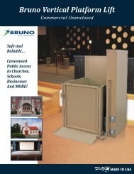
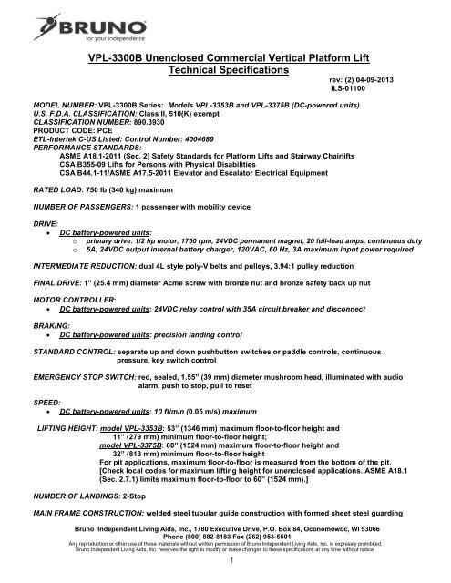
42/621<strong>VPL</strong>-3300B Unenclosed Commercial Vertical Platform LiftTechnical <strong>Specifications</strong>rev: (2) 04-09-2013ILS-01100MODEL NUMBER: <strong>VPL</strong>-3300B Series: Models <strong>VPL</strong>-3353B and <strong>VPL</strong>-3375B (DC-powered units)U.S. F.D.A. CLASSIFICATION: Class II, 510(K) exemptCLASSIFICATION NUMBER: 890.3930PRODUCT CODE: PCEETL-Intertek C-US Listed: Control Number: 4004689PERFORMANCE STANDARDS:ASME A18.1-2011 (Sec. 2) Safety Standards for Platform Lifts and Stairway ChairliftsCSA B355-09 Lifts for Persons with Physical DisabilitiesCSA B44.1-11/ASME A17.5-2011 Elevator and Escalator Electrical EquipmentRATED LOAD: 750 lb (340 kg) maximumNUMBER OF PASSENGERS: 1 passenger with mobility deviceDRIVE:• DC battery-powered units:o primary drive: 1/2 hp motor, 1750 rpm, 24VDC permanent magnet, 20 full-load amps, continuous dutyo 5A, 24VDC output internal battery charger, 120VAC, 60 Hz, 3A maximum input power requiredINTERMEDIATE REDUCTION: dual 4L style poly-V belts and pulleys, 3.94:1 pulley reductionFINAL DRIVE: 1” (25.4 mm) diameter Acme screw with bronze nut and bronze safety back up nutMOTOR CONTROLLER:• DC battery-powered units: 24VDC relay control with 35A circuit breaker and disconnectBRAKING:• DC battery-powered units: precision landing controlSTANDARD CONTROL: separate up and down pushbutton switches or paddle controls, continuouspressure, key switch controlEMERGENCY STOP SWITCH: red, sealed, 1.55” (39 mm) diameter mushroom head, illuminated with audioalarm, push to stop, pull to resetSPEED:• DC battery-powered units: 10 ft/min (0.05 m/s) maximumLIFTING HEIGHT: model <strong>VPL</strong>-3353B: 53” (1346 mm) maximum floor-to-floor height and11” (279 mm) minimum floor-to-floor height;model <strong>VPL</strong>-3375B: 60” (1524 mm) maximum floor-to-floor height and32” (813 mm) minimum floor-to-floor heightFor pit applications, maximum floor-to-floor is measured from the bottom of the pit.[Check local codes for maximum lifting height for unenclosed applications. ASME A18.1(Sec. 2.7.1) limits maximum floor-to-floor to 60” (1524 mm).]NUMBER OF LANDINGS: 2-StopMAIN FRAME CONSTRUCTION: welded steel tubular guide construction with formed sheet steel guardingBruno Independent Living Aids, Inc., 1780 Executive Drive, P.O. Box 84, Oconomowoc, WI 53066Phone (800) 882-8183 Fax (262) 953-5501Any reproduction or other use of these materials without written permission of Bruno Independent Living Aids, Inc. is expressly prohibited.Bruno Independent Living Aids, Inc. reserves the right to modify or make changes to these specifications at any time without notice.1
CARRIAGE CONSTRUCTION: welded carriage with 2.25” (57 mm) diameter front and back sealed dual-ballbearingwheels and adjustable low-friction plastic side stabilizer guide padsPLATFORM CONSTRUCTION: totally enclosed side walls consisting of 1” (25 mm) tubular framing and sheet metalsidingUNDER CARRIAGE SAFETY: totally enclosed bottom formed steel safety panAUTOMATIC LOWER RAMP: 16” (406 mm) long self lowering ramp (standard on unenclosed applications)FINISH: exterior grade powder coat paintLIMIT SWITCHES: adjustable upper and lower limit switches; upper and lower final limit switchesMANUAL LOWER DEVICE: optional; manual hand crank to lower device available; access to adaptive shaft viasafety interlocked top capREMOTE CONTROL: optional; station includes a separate landing call and send pushbutton switches orpaddle controls and a keyed on/off switchTOP LANDING GATE: optional; includes Bruno mechanical interlock which releases door, only when platformis at upper landing; electronic sensors stop platform from operating unless door is closed;also includes call/send pushbutton switches or paddle controls and keyed on/off switchmounted into gate framePLATFORM GATE: standard; includes Bruno mechanical interlock which releases door, only when platform is atlower landing. Electronic sensors stop platform from operating unless door is closedFLUSH MOUNT DOOR: optional; includes Von Duprin® electronic interlock which releases door only whenplatform is at door landing; electronic sensors stop platform from operating unlessdoor is closed; offered as an oak door with steel frame (no fire rating) or a steel doorwith steel frame (90 min. fire rating including a viewing window); delay action hydrauliccloser; keyed handleSTATIONARY RAMP: optional. 24” L x 36” W x 3” H (610 mm L x 914 mm W x 76 mm H) aluminum stationaryramp with anti-skid tan powder coat.WEIGHT OF UNIT:• DC battery-powered units:o Model <strong>VPL</strong>-3353B: 857 lb (388 kg) (without batteries) (with batteries +40 to 80 lb /18 to 36 kg)o Model <strong>VPL</strong>-3375B: 930 lb (422 kg) (without batteries) (with batteries +40 to 80 lb /18 to 36 kg• All Models:Top Landing Gate Option: 99 lb (45 kg)Top Landing Wide Gate Option: 108 lb (49 kg)TESTING PERFORMED:1) life cycle test performed at manufacturer’s location2) ASME A18.1-2011 (Sec. 2) and CSA B355-09 code tests performed at manufacturer’s locationOPTIONS:1) tool for manual lowering device2) platform canopy (not available for 90º platforms or 42” x 60” straight-through platforms)3) telephone kit (ADA compliant with battery backup)4) battery package upgrade - 34 AH battery package5) cold-weather package [recommended if operating temperature is below 20ºF (-7ºC); call Bruno ifoperating temperature is below 0ºF (-18ºC)]6) pit switch7) door/gate operator (used for power-assisted top landing door/gate)8) single timer (used with flush-mount door)Bruno Independent Living Aids, Inc., 1780 Executive Drive, P.O. Box 84, Oconomowoc, WI 53066Phone (800) 882-8183 Fax (262) 953-5501Any reproduction or other use of these materials without written permission of Bruno Independent Living Aids, Inc. is expressly prohibited.Bruno Independent Living Aids, Inc. reserves the right to modify or make changes to these specifications at any time without notice.2
<strong>VPL</strong> Job Site PreparationThe following is a list of general operations designed to prepare the job site for installation of the <strong>VPL</strong>. This list is provided as aguide to help the installer. For a complete list of requirements check the installation site’s applicable local codes.Electrical Requirements:• DC battery-powered units: require a dedicated GFCI 120V, 3A (max.), 60 Hz single-phase circuit to operate theinternal battery charger. Check applicable local codes for all electrical and wiring requirements.Platform Pathway Requirements:Make sure the pathway that the platform runs in is clear of any electrical conduit and wire ways. Make sure no liquids, steamor gas piping discharge into the pathway, and make sure that there is sufficient headroom clearance (minimum of 80”– 2032mm) throughout floor-to-floor travel. Make sure the area is sufficiently lit.Floor Recommendations:4” (102 mm) thick, 3500 PSI minimum compressive strength, reinforced concrete slab. Refer to technical drawings forminimum slab dimensions. If the temperature can fall below freezing, it is recommended that you insert an insulationsheet between the concrete slab and the compacted rock.Floor Attachment:<strong>VPL</strong> must be fastened to concrete slab using four (4) 1/2” (3/8” bolt) x minimum 2-1/2” long concrete anchors suitable for theenvironment. Refer to technical drawings for mounting hole locations. Follow selected concrete anchor manufacturer’sguidelines and applicable codes.Housing Attachment:None required. Can use 5/16-18 tapped holes on tower frame work to fasten the tower housing to a vertical wall foradditional stability. Note: Housing must remain intact.Top Gate Attachment:Refer to <strong>VPL</strong> gate technical drawing (see below).Flush Mount Door Attachment:Refer to <strong>VPL</strong> flush mount door detail drawing (see below).Space Requirements:Refer to technical drawings (see below).Platform-to-Top Landing Sill Clearance:ASME code indicates the platform floor-to-sill clearance at the upper landing shall not be less than 3/8” (9.5 mm) nor exceed3/4” (19 mm). Follow applicable local codes.Fascia Wall Requirements:ASME code indicates that fascia should be smooth and non-perforated that guards the full length and width of the platform.The fascia shall be securely fastened from the upper landing sill down to the lower landing sill. It should also be able towithstand a 125-pound side load over any 4-inch square area. Follow applicable local codes.Technical Drawings (available at www.bruno.com):• ILS-00938 Top Landing Gate Detail• ILS-01027 Flush Mount Door Detail• ILS-01102 Unenclosed Straight-Through Platorm With Platform Gate (No Pit)• ILS-01103 Unenclosed Straight-Through Platorm With Platform Gate (Pit Application)• ILS-01104 Unenclosed 90º/Adjacent-Exit Platform With Platform Gate (No Pit)• ILS-01105 Unenclosed 90º/Adjacent-Exit Platform With Platform Gate (Pit Application)Bruno Independent Living Aids, Inc., 1780 Executive Drive, P.O. Box 84, Oconomowoc, WI 53066Phone (800) 882-8183 Fax (262) 953-5501Any reproduction or other use of these materials without written permission of Bruno Independent Living Aids, Inc. is expressly prohibited.Bruno Independent Living Aids, Inc. reserves the right to modify or make changes to these specifications at any time without notice.3