Access/MultiView Electric Pro jec tion Screen & Masking System by ...
Access/MultiView Electric Pro jec tion Screen & Masking System by ...
Access/MultiView Electric Pro jec tion Screen & Masking System by ...

Create successful ePaper yourself
Turn your PDF publications into a flip-book with our unique Google optimized e-Paper software.
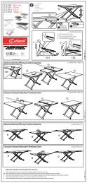
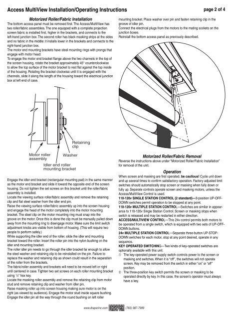
<strong>Access</strong> <strong>MultiView</strong> Installa<strong>tion</strong>/Operating Instruc<strong>tion</strong>s page 2 of 4Motorized Roller/Fabric Installa<strong>tion</strong>The bottom access panel must be removed fi rst. The <strong>Access</strong>/<strong>MultiView</strong> hastwo roller/fabric assemblies. The one equipped with a complete pro<strong>jec</strong><strong>tion</strong>screen fabric is installed first, higher in the brackets, and connects to theleft-hand junc<strong>tion</strong> box. The second roller has black masking strips at the sidesand no fabric in the middle: it installs lower in the brackets and connects to theright-hand junc<strong>tion</strong> box.The motor end mounting brackets have steel mounting rings with prongs thatengage with motor head.To engage the motor end bracket fl ange above the two channels in the top ofthe screen housing, rotate the bracket approximately 45° counterclockwiseto allow the top surface of the motor bracket to rest fl at against the top insideof the housing. Rotating the bracket clockwise until it is engaged with thechannels, slide it along the length of the housing toward the electrical junc<strong>tion</strong>box at left end of case.mounting bracket. Place washer over pin and fasten retaining clip in thegroove of idler pin.Connect the electrical plugs from the motors to the mating sockets on thejunc<strong>tion</strong> boxes.Reinstall the bottom access panel as previously described.RetainingclipMotor roller WasherassemblyIdler end rollermounting bracketEngage the idler end bracket (rectangular mounting pad) in the same manneras the motor end bracket and slide it toward the opposite end of the screenhousing. Do not tighten the set screws on this bracket until the roller/fabricassembly is installed.Locate the viewing surface roller/fabric assembly and remove the retainingclip and flat steel washer from the idler end pin.Raise the viewing surface roller/fabric assembly up into the screen housingand engage the head of the motor completely into the motor mountingbracket. The steel clip on the motor mounting ring must snap into thegroove on the motor. Once this is done the clip must be manually pulled downaway from the mounting ring to disengage motor. Make sure the limit switchadjustment knobs are visible from bottom of housing. (This will require twopeople to perform safely.)While supporting the idler end of the roller, slide the idler end mountingbracket toward the roller. Insert the roller pin into the nylon bushing on theidler end mounting bracket.The roller idler pin needs to go through the idler bracket far enough to allowthe steel washer and retaining clip to be reinstalled on the pin. Failure toreplace the washer and retaining clip as shown could result in the separa<strong>tion</strong>of the roller from the brackets.The fabric/roller assembly and brackets will need to be moved left or rightuntil centered in case. Tighten two set screws on each roller mounting bracketusing 1 /8" hex key.Locate the masking roller assembly and remove the retaining clip from motorstud and remove retaining clip and washer from idler pin.Raise masking roller up into screen housing making sure motor is on theright (as viewed <strong>by</strong> audience). Engage the motor stud inside square bushing.Engage the idler pin all the way through the round bushing on left rollerMotorized Roller/Fabric RemovalReverse the instruc<strong>tion</strong>s above under “Motorized Roller/Fabric Installa<strong>tion</strong>”for removal of the unit.Opera<strong>tion</strong>When screen and masking are first operated, be cautious! Cycle unit downand up several times to confi rm satisfactory opera<strong>tion</strong>. Factory adjusted limitswitches should automatically stop screen or masking when fully down orfully up. Separate controls operate screen and masking motors, unless the<strong>Access</strong>/<strong>MultiView</strong> Control is used.110-120v SINGLE STATION CONTROL (2 standard)—3-posi<strong>tion</strong> UP-OFF-DOWN switches permit opera<strong>tion</strong> to be stopped at any point.110-120v MULTIPLE STATION CONTROL—Switches are similar in appearanceto 110-120v Single Sta<strong>tion</strong> Control. <strong>Screen</strong> or masking stops whenswitch is released and may be restarted in either direc<strong>tion</strong>.ACCESS/MULTIVIEW CONTROL—This 24v control permits both motors tobe operated from a single switch, which is equipped with two sets of UP-OFF-DOWN buttons.24v MULTIPLE STATION CONTROL—Separate three-button UP-STOP-DOWN switches for each motor, stop at any point desired, operate in anysequence.KEY OPERATED SWITCHING—Two kinds of key-operated switches areop<strong>tion</strong>ally available with this unit.➀ The key-operated power supply switch controls power to the screen ormasking and switches. When it is “off”, the switches will not operatescreen. Key may be removed from the switch in either “on” or “off”posi<strong>tion</strong>.➁ The three-posi<strong>tion</strong> key switch permits the screen or masking to beoperated directly <strong>by</strong> key. In this case, the screen’s operator must alwayshave a key.www.draperinc.com (765) 987-7999