THE VIBRATORY PILE INSTALLATION TECHNIQUE - Viking
THE VIBRATORY PILE INSTALLATION TECHNIQUE - Viking
THE VIBRATORY PILE INSTALLATION TECHNIQUE - Viking

You also want an ePaper? Increase the reach of your titles
YUMPU automatically turns print PDFs into web optimized ePapers that Google loves.
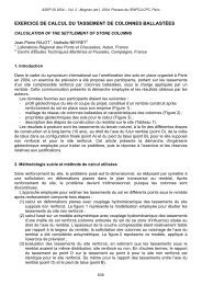
2.1.3. Driving frequencyf d is specified by the revolution per second of the eccentric weights [Hz], sometimes alsospecified as revolution per minute n [rpm]. Another common expression is revolution in radiansper second ω [rad/s]. The three different ways can be combined as follows: ω =2πf d =2πn/60.time [s]ω [rad/s]F oω = 2πf dF o^F v= ξM e( 2πf d) 2F da.) Driving force F dvs. timeT=1/f dDriving force: F d25% . M e50% . M e75% . M e100% . M eb.) Peak value of F dvs. M eand f dFigure 2. Driving force as a function of changed frequency and eccentric moment.2.1.4. System efficiencyξ which is applied to the dynamic part, (centrifugal force F v ), of the theoretical expression of thedriving force F d (see equation below). Since the actual driving force F d delivered to the pile headwill always be less than the theoretically rated.The theoretical peak amplitude of the driving force F d in [kN] can be assessed by the followingexpression.F d = F o + ξF v = F o + ξM e ω 2 = F o [kN] + ξ [-] M e [kg-m] (2πn) 2 [rpm] 22.2. Parts and type of vibro-unitsThe main parts of modern vibro-units consist of the following parts.Bias mass; a part of the vibrator that’s also called ‘suppressor housing’ which is the nonvibratingpart of the unit. It connects to the exciter block via elastomers pads that isolate thedynamic motion of the exciter block from being transmitted to either crane line or leader mast,which connects, to the bias mass. To the bias mass are also electrical cables, hydraulic hosesmast connected.Elastomer pads (or springs); connects and at the same time isolates the non-vibrating part fromthe vibrating part of the vibro-unit.Exciter block; contains the rotating eccentric weights, gearbox and hydraulic motor, whichcombined generates the sinusoidal motion and centrifugal force of the vibrator.Clamp; at the bottom of the vibro-unit, which forms the rigid connection between pile and vibrounit.Used to transfer the generated force and motion, (preferably ‘axially’), to the pile profile.The clamp must be adapted to the size of the vibro as well as to the shape of the pile.Five different types of vibratory drivers (free or leader mounted) can be distinguished, based onapplied driving frequency (f d [Hz]) and eccentric moment (M e [kg-m]), see Table I.Table I. Type of modern vibratory drivers/extractors.68