125, 140, 180 models - Rapid Welding and Industrial Supplies Ltd
125, 140, 180 models - Rapid Welding and Industrial Supplies Ltd
125, 140, 180 models - Rapid Welding and Industrial Supplies Ltd

You also want an ePaper? Increase the reach of your titles
YUMPU automatically turns print PDFs into web optimized ePapers that Google loves.
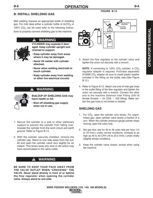
B-8B. INSTALL SHIELDING GASOPERATIONFIGURE B.13B-8MIG welding requires an appropriate bottle of shieldinggas. For mild steel either a cylinder bottle of Ar/CO 2 or100% CO 2 can be used refer to the following instructionsto properly connect shielding gas to the machine.WARNING75/25CYLINDER may explode if damaged.Keep cylinder upright <strong>and</strong>chained to support• Keep cylinder away from areaswhere it may be damaged.• Never lift welder with cylinderattached.• Never allow welding electrode totouch cylinder.• Keep cylinder away from weldingor other live electrical circuits.-----------------------------------------------------------------------WARNINGBUILDUP OF SHIELDING GAS mayharm health or kill.• Shut off shielding gas supplywhen not in use.MALE ENDCO2100%FEMALE ENDMIXESREGULATORADAPTERPLASTICWASHERS192983. Attach the flow regulator to the cylinder valve <strong>and</strong>tighten the union nut securely with a wrench.NOTE: If connecting to 100% CO 2 cylinder, a CO 2regulator adapter is required. Purchase separatelyS19298 CO 2 adapter be sure to install plastic washerincluded in the fitting on the bottle side.(See FigureB.13 )4. Refer to Figure B.13. Attach one end of inlet gas hoseto the outlet fitting of the flow regulator <strong>and</strong> tighten theunion nut securely with a wrench. Connect the otherend to the machine Solenoid Inlet Fitting (5/8-18female threads — for CGA — 032 fitting). Make certainthe gas hose is not kinked or twisted.SHIELDING GASOPERATORʼS MANUAL1. Secure the cylinder to a wall or other stationarysupport to prevent the cylinder from falling over.Insulate the cylinder from the work circuit <strong>and</strong> earthground. Refer to Figure B.13.2. With the cylinder securely installed, remove thecylinder cap. St<strong>and</strong> to one side away from the outlet<strong>and</strong> open the cylinder valve very slightly for aninstant. This blows away any dust or dirt which mayhave accumulated in the valve outlet.1. For CO 2 , open the cylinder very slowly. For argonmixedgas, open cylinder valve slowly a fraction of aturn. When the cylinder pressure gauge pointer stopsmoving, open the valve fully.2. Set gas flow rate for 30 to 40 cubic feet per hour (14to 18 I/min.) under normal conditions, increase to ashigh as 40 to 50 CFH (18 to 23.5 I/min.) under drafty(slightly windy) conditions.3. Keep the cylinder valve closed, except when usingthe machine.WARNINGBE SURE TO KEEP YOUR FACE AWAY FROMTHE VALVE OUTLET WHEN “CRACKING” THEVALVE. Never st<strong>and</strong> directly in front of or behindthe flow regulator when opening the cylindervalve. Always st<strong>and</strong> to one side.-----------------------------------------------------------------------WIRE FEEDER WELDERS (<strong>125</strong>, <strong>140</strong>, <strong>180</strong> MODELS)