Cockcroft-Walton Voltage Multiplier - STEM2
Cockcroft-Walton Voltage Multiplier - STEM2
Cockcroft-Walton Voltage Multiplier - STEM2

Create successful ePaper yourself
Turn your PDF publications into a flip-book with our unique Google optimized e-Paper software.
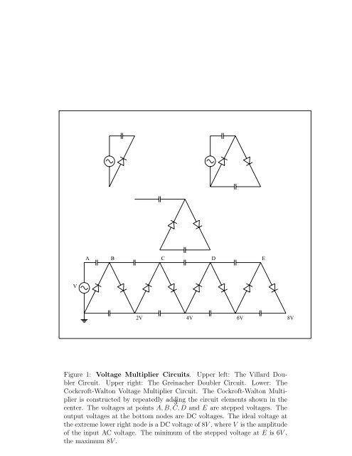
A B C D EV2V 4V 6V 8VFigure 1: <strong>Voltage</strong> <strong>Multiplier</strong> Circuits. Upper left: The Villard DoublerCircuit. Upper right: The Greinacher Doubler Circuit. Lower: The<strong>Cockcroft</strong>-<strong>Walton</strong> <strong>Voltage</strong> <strong>Multiplier</strong> Circuit. The Cockroft-<strong>Walton</strong> <strong>Multiplier</strong>is constructed by repeatedly adding 3 the circuit elements shown in thecenter. The voltages at points A, B, C, D and E are stepped voltages. Theoutput voltages at the bottom nodes are DC voltages. The ideal voltage atthe extreme lower right node is a DC voltage of 8V , where V is the amplitudeof the input AC voltage. The minimum of the stepped voltage at E is 6V ,the maximum 8V .