Cockcroft-Walton Voltage Multiplier - STEM2
Cockcroft-Walton Voltage Multiplier - STEM2
Cockcroft-Walton Voltage Multiplier - STEM2
Create successful ePaper yourself
Turn your PDF publications into a flip-book with our unique Google optimized e-Paper software.
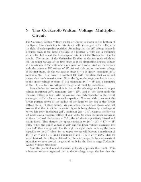
5 The <strong>Cockcroft</strong>-<strong>Walton</strong> <strong>Voltage</strong> <strong>Multiplier</strong>CircuitThe <strong>Cockcroft</strong>-<strong>Walton</strong> <strong>Voltage</strong> multipler Circuit is shown at the bottom ofthe figure. Every calacitor in this circuit will be charged to 2V volts, withthe right of each capacitor positive. Assuming that the AC voltage source isa square wave, it will have a voltage of a positive V volts and a minimumof -V volts. Let us call the first stage of this circuit the Greinacher Doublercircuit. The output of the Greinacher Doubler at the top node which wecall the upper voltage of the first stage is at an alternating stepped voltageof a maximum of 2V volts and a minimum of 0 volts. And at the bottomnode the constant DC voltage of 2V. We call this output the lower voltageof the first stage. So the voltages at stage n = 1 is upper: maximum 2nV,minimum 2(n − 1)V , lower: a constant DC 2nV . We claim that as we addstages, this result remains true. So in the figure the stage number is n = 4,so the upper voltage at point E is a maximum 2nV = 8V and a minimumof 2(n − 1)V = 6V . We will prove the general result by induction.So our induction assumption is that at the nth stage we have an uppervoltage maximum 2nV, minimum 2(n − 1)V , and at the lower node theconstant voltage is 2nV . Also we assume that each capacitor in the circuitis charged to 2V volts across each capacitor. Now we wish to connect thecircuit portion shown at the middle of the figure to the end of this circuitgetting the n + 1 stage circuit. We can ignore the previous stages and justassume that the circuit in the center figure is being driven by a voltage atits top left node, maximum 2nV , minimum 2(n − 1)V , whereas the bottomleft node is at a constant voltage of 2nV volts. So when the upper voltage isat 2(n − 1)V and the bottom at 2nV , the left diode is positively biased andcharge flows. Thes charges the upper capacitor to 2nV − 2(n − 1)V = 2Vvolts. When the upper voltage is 2nV and the lower voltage is slightly lessthan 2nV then charge will flow through the right diode to bring the lowercapacitor to the 2V value. So the upper voltage will become a maximum of2nV + 2V = 2(n + 1)V and a minimum of 2(n − 1)V + 2V = 2nV . Thus wehave obtained the voltages claimed for the n + 1 stage. So by mathematicalinduction we have proved the general result for the ideal n stage <strong>Cockcroft</strong>-<strong>Walton</strong> <strong>Voltage</strong> <strong>Multiplier</strong>.Now the practical nonideal circuit will only approach this result. Thisis because we have neglected the the diode voltage drops, the fact that the6


