35401.1 PKZ Archer RTF BNF manual.indb - Robot MarketPlace
35401.1 PKZ Archer RTF BNF manual.indb - Robot MarketPlace
35401.1 PKZ Archer RTF BNF manual.indb - Robot MarketPlace

You also want an ePaper? Increase the reach of your titles
YUMPU automatically turns print PDFs into web optimized ePapers that Google loves.
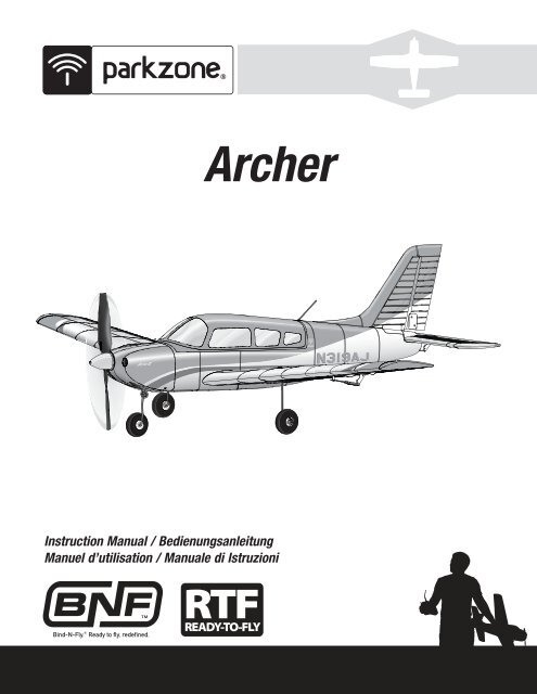
<strong>Archer</strong>Instruction Manual / BedienungsanleitungManuel d’utilisation / Manuale di Istruzioni
ENNOTICEAll instructions, warranties and other collateral documents are subject to change at the sole discretion of Horizon Hobby, Inc. For up-to-date productliterature, visit www.horizonhobby.com and click on the support tab for this product.Meaning of Special Language:The following terms are used throughout the product literature to indicate various levels of potential harm when operating this product:NOTICE: Procedures, which if not properly followed, create a possibility of physical property damage AND little or no possibility of injury.CAUTION: Procedures, which if not properly followed, create the probability of physical property damage AND a possibility of serious injury.WARNING: Procedures, which if not properly followed, create the probability of property damage, collateral damage, and serious injury OR create a highprobability of superfi cial injury.WARNING: Read the ENTIRE instruction <strong>manual</strong> to become familiar with the features of the product before operating. Failure to operate the productcorrectly can result in damage to the product, personal property and cause serious injury.This is a sophisticated hobby product. It must be operated with caution and common sense and requires some basic mechanical ability. Failure to operatethis Product in a safe and responsible manner could result in injury or damage to the product or other property. This product is not intended for useby children without direct adult supervision. Do not attempt disassembly, use with incompatible components or augment product in any way without theapproval of Horizon Hobby, Inc. This <strong>manual</strong> contains instructions for safety, operation and maintenance. It is essential to read and follow all the instructionsand warnings in the <strong>manual</strong>, prior to assembly, setup or use, in order to operate correctly and avoid damage or serious injury.Age Recommendation: Not for children under 14 years. This is not a toy.Safety Precautions and WarningsAs the user of this product, you are solely responsible for operating in a mannerthat does not endanger yourself and others or result in damage to the productor the property of others.• Always keep a safe distance in all directions around your model to avoidcollisions or injury. This model is controlled by a radio signal subject tointerference from many sources outside your control. Interference can causemomentary loss of control• Always operate your model in open spaces away from full-size vehicles,traffi c and people.• Always carefully follow the directions and warnings for this and any optionalsupport equipment (chargers, rechargeable battery packs, etc.).• Always keep all chemicals, small parts and anything electrical out of thereach of children.• Always avoid water exposure to all equipment not specifi cally designed andprotected for this purpose. Moisture causes damage to electronics.• Never place any portion of the model in your mouth as it could cause seriousinjury or even death.• Never operate your model with low transmitter batteries.• Always keep aircraft in sight and under control.• Always use fully charged batteries.• Always keep transmitter powered on while aircraft is powered.• Always remove batteries before disassembly.• Always keep moving parts clean.• Always keep parts dry.• Always let parts cool after use before touching.• Always remove batteries after use.• Always ensure failsafe is properly set before fl ying.• Never operate aircraft with damaged wiring.• Never touch moving parts.Battery WarningThe Battery Charger included with your aircraft is designed to safely balance and charge the Li-Po battery.CAUTION: All instructions and warnings must be followed exactly. Mishandling of Li-Po batteries can result in a fi re, personal injury, and/or property damage.• By handling, charging or using the included Li-Po battery, you assume allrisks associated with lithium batteries.• If at any time the battery begins to balloon or swell, discontinue use immediately.If charging or discharging, discontinue and disconnect. Continuingto use, charge or discharge a battery that is ballooning or swelling can resultin fi re.• Always store the battery at room temperature in a dry area for best results.• Always transport or temporarily store the battery in a temperature range of40–120º F (5–49º C). Do not store the battery or aircraft in a car or directsunlight. If stored in a hot car, the battery can be damaged or evencatch fi re.• Always charge batteries away from fl ammable materials.• Always inspect the battery before charging and never chargedamaged batteries.• Always disconnect the battery after charging, and let the charger coolbetween charges.• Always constantly monitor the temperature of the battery packwhile charging.• ONLY USE A CHARGER SPECIFICALLY DESIGNED TO CHARGE LI-PO BATTER-IES. Failure to charge the battery with a compatible charger may cause fi reresulting in personal injury and/or property damage• Never discharge Li-Po cells to below 3V under load.• Never cover warning labels with hook and loop strips.• Never leave charging batteries unattended.• Never charge batteries outside recommended levels.• Never attempt to dismantle or alter the charger.• Never allow minors to charge battery packs.• Never charge batteries in extremely hot or cold places (recommendedbetween 40–120° F or 5–49° C) or place in direct sunlight.2
– Introduction –As you’re about to fi nd out, the compact size, scale good looks and no-nonsense fl ight characteristics of the ParkZone ® <strong>Archer</strong> aircraft make it excellent companyto have around almost anywhere. At home, on the road or on your lunch break, you’ll have no trouble fi nding the time or opportunity to fl y. Assembly couldn’tbe easier. In fact, you’ll probably have it together and ready for its maiden fl ight well before the battery has fi nished charging.If the <strong>Archer</strong> is the fi rst sport plane you’ve fl own since soloing a trainer, you’ll fi nd the transition is an easy one. Like most trainers, it has tricycle landing gearand plenty of dihedral, so you should feel right at home during takeoffs and landings. About the only difference is in the shape of the wing. Unlike the fl at-bottomairfoils on a lot of high-wing trainers, the semi-symmetrical airfoil makes the aircraft less likely to fl oat and may require a touch more speed on landings. You’llwant to factor that into your approach profi le as you prepare for that fi rst landing.Whatever your experience level, though, you must take some time to read this <strong>manual</strong>. In addition to instructions for fi nal assembly, you’ll fi nd handy setup tips,important battery charging precautions and a helpful troubleshooting guide. It’s all here to make sure your fi rst fl ight, and every one after it, is as successful ascan be.Box ContentsENIncludesTable of ContentsCharging the Flight Battery ............................................................... 4Low Voltage Cutoff (LVC) ................................................................... 4Installing the Transmitter Batteries .................................................... 5Understanding the Controls of the DX4e Transmitter ......................... 5DX4e Range Check ........................................................................... 6Transmitter and Receiver Binding ...................................................... 7Installing the Battery ......................................................................... 7Arming the ESC and Receiver............................................................ 8Installing the Horizontal Stabilizer ..................................................... 9Control Horn and Servo Arm Settings ................................................ 9Installing the Wing .......................................................................... 10Control Surface Centering and Installing Clevises on Control Horns . 10Installing the Landing Gear ............................................................. 11Center of Gravity (CG) ..................................................................... 11Control Direction Test ...................................................................... 12Dual Rates ...................................................................................... 12Flying Tips and Repairs ................................................................... 13First Flight Preparation .................................................................... 13Maintenance After Flying ................................................................ 13Removing the Nose Gear Nose Gear Service ................................... 14Service of Power Components ........................................................ 14AMA National Model Aircraft Safety Code ........................................ 15Troubleshooting Guide .................................................................... 16Limited Warranty ............................................................................ 17Contact Information ........................................................................ 17FCC Information .............................................................................. 18Compliance Information for the European Union .............................. 18Parts Contact Information ............................................................... 67Replacement Parts .......................................................................... 67Optional Parts ................................................................................. 68Specifications36.8 inches (935mm)Installed Installed370 Brushless Outrunner Motor, 1300Kv (<strong>PKZ</strong>6116)Installed Installed10-Amp Pro Brushless ESC (EFLA1010)(2) Aileron Servos (<strong>PKZ</strong>1081)(1) Rudder Servo (1) Elevator Servo (<strong>PKZ</strong>1080)Spektrum AR400 4-Channel DSM2 ® /DSMX ®Aircraft ReceiverBattery: 7.4V 2S 1300mAh 20C Li-Po(EFLB13002S20)Battery Charger: 2S DC Li-Po balancing charger(EFLC3125)Recommended Transmitter:Full-Range 4-Channel 2.4GHz with Spektrum DSM2 ® /DSMX ® technology.25.6 inches (650mm)Weight: 16.4 oz(466 g)Installed InstalledInstalled InstalledIncluded IncludedIncluded IncludedNeeded toCompleteDX4eIncludedTo register your product online, visit www.parkzone.com3
ENInstalling the Transmitter BatteriesYour Spektrum DX4e comes prebound to the aircraft.1 23Remove the battery cover, install the four included batteries (noting properpolarity) and reinstall the battery cover.Low Battery AlarmWhen the battery voltage drops below 4.7 volts, an alarm sounds and thevoltage LEDs fl ash. The batteries must be replaced immediately. If thishappens while fl ying, land your aircraft as soon and as safely as possible.Understanding the Controls of the DX4e TransmitterKEYA AntennaB HandleC Trainer/Bind Button (Modes 1/3 only)D Hi/Lo Rate SwitchE Right Control StickF Trim Slider (for up/down on stick)G Neck Strap ConnectionH Trim Slider (for left/right on stick)I Mode Switch (1/3 or 2/4)J Mix Switch (Elevon only)K Servo Reverse SwitchesL Power Switch (ON/OFF)M Trim Slider (for left/right on stick)N Trim Slider (for up/down on stick)O Left Control StickP LEDsQ ACT/AUX Switch (Channel 5)QPONMLKRSTRTrainer/Bind Button (Modes 2/4 only)Battery CoverTrainer PortCABDEFGHIJTSFor more information on the transmitter, go tohttp://www.horizonhobby.com/products/dx4e-dsmx-4-channel-full-range-tx-onlymd2-4-SPMR4400and click on the supporttab for the Spektrum DX4e to download theinstruction <strong>manual</strong>.* The diagram shows the transmitter controls for Mode 2 and Mode 1 transmitters.Trainer/Bind Button ((C) Mode 1 or (R) Mode 2)The Trainer/Bind Button is used during binding or when connecting a trainercord (SPM6805) to the trainer port (T). For complete binding instructions, referto the binding section in this <strong>manual</strong>.When using the trainer function, connect the trainer cord into the trainer portin both the master (instructor) and the slave (student) transmitters. The mastertransmitter must be powered ON and bound to the receiver. The slave transmittermust be powered OFF. Any time you press and hold the trainer buttonon the master, it will give control authority to the slave. Releasing the trainerbutton returns control to the master.IMPORTANT: The slave transmitter must always have the same reverse settingsas the master.Hi/Lo Rate Switch (D)This switch supports high and low rate functions on aileron, elevator andrudder channels. In the upper, or “HI” position, servo travel is 100% on thesechannels. In the lower, or “LO”, position, servo travel decreases to 70% onthese channels. This switch lets you quickly change control rates from high foraggressive maneuvers to low for smooth, precise maneuvers. When learningto fl y, use low rate.Mode Switch (I)This switch changes channel assignments to the control sticks. Always ensurethe controls respond as desired before fl ying. A Mode 1 transmitter may beswitched to Mode 3, while a Mode 2 transmitter may be switched to Mode 4.Mix Switch (J)This switch enables a mix for elevons on Delta wing aircraft. If needed, referto the transmitter <strong>manual</strong> for more information.5
ENServo Reversing Switches (K)These switches select the servo direction of each channel. Use your fi ngernailor a small screwdriver to change the switch position to normal (NOR) orreverse (REV) as needed to make transmitter controls operate the model asdesired. Perform the Control Direction Test before fl ying.ACT/AUX Switch (Q)This switch activates a receiver channel (such as servos) connected throughan AUX channel of the receiver.France RF SettingThe DX4e has a France RF setting that complies with French regulations. TheFrance RF setting should only be turned on when operating your transmitter inFrance outdoors.1To set France mode (Illustration 1 below):Push and hold the trainer button on the top of the transmitter while pushingand holding the two sticks as shown below, then power ON the transmitter.After hearing a series of descending beep tones (high to low), release thetrainer switch and the sticks. The France setting is now turned on. Bind thetransmitter to the receiver for the change to take effect.To set Standard mode (Illustration 2 below):Push and hold the trainer button on the top of the transmitter while pushingand holding the two sticks as shown below, then power ON the transmitter. Afterhearing a series of ascending beep tones (low to high), release the trainerswitch and the sticks. The France setting is turned off.2DX4e Range CheckPlacing the transmitter in RANGE CHECK mode reduces the output power,allowing a range check.DX4e Transmitter Range Check ProcessBefore performing the range check, ensure the correct failsafe stickpositions are established.1. With the system powered on and the model restrained on theground*, stand 90ft/28m away from the model.2. Face the model with the transmitter in your normal fl ying position.3. Push and hold the trainer button while toggling the Hi/Lo Rate Switchfour times.4. The LEDs will fl ash and the alarm will sound. The system is in rangecheck mode.IMPORTANT: You must hold the trainer button during the entire rangecheck process. Releasing the button switch will exit the range checkmode.You should have total control of the model with the trainer button held at90ft/28m meters.28 meters (90 feet)*In some aircraft, when the model is placed on the ground, the antenna(s)can be within inches of the ground. Close proximity of the antenna(s) to theground can reduce the effectiveness of the range check. This is called pulling.If you experience issues during the range check, restrain the model on a nonconductivestand or table up to 2ft (60cm) above the ground. Then range checkthe system again.If control issues exist, contact the appropriate Product Support Department forassistance, or visit the Spektrum website for more information.6
ENTransmitter and Receiver BindingBinding is the process of programming the receiver to recognize the GUID (Globally Unique Identifi er) code of a single specifi c transmitter. You need to ‘bind’ yourchosen Spektrum DSM2 ® /DSMX ® technology equipped aircraft transmitter to the receiver for proper operation (Please visit www.bindnfl y.com for a complete listof compatible transmitters).CAUTION: When using a Futaba ® transmitter with a Spektrum DSM ® module, you must reverse the throttle channel and rebind. Refer to your Spektrummodule <strong>manual</strong> for binding and failsafe instructions. Refer to your Futaba transmitter <strong>manual</strong> for instructions on reversing the throttle channel.Binding Procedure Reference Table (<strong>RTF</strong> Version: Your Spektrum DX4e comes prebound to the aircraft.)1. Read the transmitter instructions for binding to a receiver (location of transmitter’s Bind control).2. Make sure the transmitter is powered OFF.3. Move the transmitter controls to neutral (fl ight controls: rudder, elevators and ailerons) or to lowpositions (throttle, throttle trim).*BIND PLUG4. Install a bind plug in the receiver bind port.5. Connect the fl ight battery to the ESC. The ESC will produce a series of sounds. One long tone,then two short tones confi rm that the LVC is set for the ESC.6. The receiver LED will begin to fl ash rapidly.7. Power ON the transmitter while holding the transmitter bind button or switch. Refer to yourtransmitter’s <strong>manual</strong> for binding button or switch instructions.For the DX4e, release the trainer/bind button once the LEDs fl ash and a series of beeps sound.Within a few seconds, the system should connect.8. When the receiver binds to the transmitter, the light on the receiver will turn solid and the ESCwill produce a series of three ascending tones. The tones indicate the ESC is armed, providedthe throttle stick and throttle trim are low enough to trigger arming.9. Remove the bind plug from the bind port.10. Safely store the bind plug (some owners attach the bind plug to their transmitter using two-partloops and clips).11. The receiver should retain the binding instructions received from the transmitter until anotherbinding is done.* The throttle will not arm if the transmitter’s throttle control is not put at the lowest position. If you encounter problems, follow the binding instructions andrefer to the transmitter troubleshooting guide for other instructions. If needed, contact the appropriate Horizon Product Support offi ce.Installing the Battery1. Push the antenna (A) into the fuselage, releasing the canopy latch.A2. Lift the back of the canopy and pull backwards to remove the canopy.3. Install the fully charged battery (B) in the battery compartment. See theAdjusting the Center of Gravity instructions for more information.4. Make sure the fl ight battery is secured using the hook and loop strap (C).5. Reinstall the canopy. Push the rear of the canopy securely to ensure thelatch is fully engaged.BC7
ENArming the ESC and ReceiverArming the ESC also occurs after binding as previously described, butsubsequent connection of a fl ight battery requires the steps below.1CAUTION: Always keep hands away from the propeller. When armed,the motor will turn the propeller in response to any throttle movement.CAUTION: Always disconnect the Li-Po battery from the aircraft receiverwhen not fl ying to avoid over-discharging the battery. Batteries discharged to avoltage lower than the lowest approved voltage may become damaged,resulting in loss of performance and potential fi re when batteries are charged.1. Power ON the transmitter and lower the throttle and throttle trim to theirlowest settings.2DO NOT connect the battery while the throttle stick is at full or the ESC will gointo programming mode. If a musical tone sounds after 5 seconds, immediatelydisconnect the battery, then lower the throttle.2. Remove the canopy and install the fully charged battery in the batterycompartment using the hook and loop strip, then connect the battery tothe ESC.3. When power is applied to the ESC:1) The ESC will sound two tones to indicate that LVC is properly set.2) An LED will light on the receiver.38
ENInstalling the Horizontal Stabilizer1. Connect the linkage (A) to the outermost hole on the elevatorcontrol horn (B). You will need to rotate the horizontal stabilizer to attachthe z-bend of the pushrod to the control horn on the elevator.Tip: Move the elevator servo arm to full travel. This moves the pushrodrearward to give the most room to install the horizontal stabilizer. Make sure tocenter the servo again before fl ight.2. Slide the horizontal stabilizer into the slot and align the two pins at the frontof the horizontal stabilizer to the plastic stabilizer mount on the fuselage.3. Turn the rudder to the right or left and secure the horizontal tail to thefuselage using a screw (C).When needed, disassemble in reverse order.ABCControl Horn and Servo Arm SettingsFly the model at factory settings before making changes. For pilots who wish tofl y the model with more or less control throw, adjust the position of the linkageson the servo arms and control horns for increased travel.HornsArmsAlways ensure the steering linkage on the rudder servo arm is correctlyadjusted so the model steers straight when the rudder control is at neutral.ElevatorMore control throw Less control throw NoseGearSteeringRudderAilerons9
ENInstalling the Wing1. Remove the canopy from the fuselage.2. Turn the wing and fuselage over so their bottom sides face up.3. Place the wing’s aileron servo connectors (A) into the hole in the fuselage.4. Slide the two guide pins (B) at the rear of the wing into the two holes inthe fuselage.5. Align and attach the wing to the fuselage using two screws (C).6. Inside the fuselage, connect both aileron servo connectors to the aileronY-harness connectors. The left and right aileron servos can be connected toeither side of the Y-harness.BWhen needed, disassemble in reverse order.CAUTION: DO NOT crush or otherwise damage wiring when attachingthe wing to the fuselage.Control Surface Centering andInstalling Clevises on Control HornsATip: Turn the clevis on the linkage to change the length of the linkagebetween the servo arm and the control horn.• Pull the tube from the clevis to the linkage.• Carefully spread the clevis, then insert the clevis pin into the desiredhole in the control horn.• Move the tube to hold the clevis on the control horn.After binding a transmitter to the model receiver, set the trims andsub-trims to 0, then adjust the clevises to center the control surfaces.C1.4.2.5.3.6.10
ENInstalling the Landing Gear1. Turn the fuselage so that the bottom of the wing faces up.2. Install the main landing gear by inserting the main gear struts (A) into thecorresponding gear plate hole located on each wing.A3. Carefully turn each strut in the gear plate until the horizontal section of thestrut snaps into place.When needed, disassemble in reverse order.Center of Gravity (CG)The CG location is 40mm back from the leading edge of the wing. Install thefl ight battery all the way to the front of the battery compartment. Make surethe fl ight battery is secured using the hook and loop strap. It is easiest to balancethe <strong>Archer</strong> with the aircraft inverted.40mm1.60 inchesback from theleading edge ofthe wing.11
ENControl Direction TestMove the controls on the transmitter to make sure the aircraft control surfaces move correctly and in the proper direction. After performing the Control Test,correctly set the failsafe. Make sure the transmitter controls are at neutral and the throttle and throttle trim are in the low position, then rebind the model to yourtransmitter. If the receiver loses its link to the transmitter, the failsafe will drive the servos to these settings made at binding.Transmitter CommandAircraft ReactionElevatorUp Elevator CommandDown Elevator CommandAileronStick RightStick LeftRudderStick RightStick LeftDual RatesYour DSM2/DSMX full range transmitter features dual rates to help you selectthe amount of travel that you want from the control surfaces.High RateLow RateAileron 12mm up/down 9mm up/downElevator 9mm up/down 7mm up/downRudder 12mm left/right 8mm left/right12
ENFlying Tips and RepairsConsult local laws and ordinances before choosing a fl ying location.Range Check your Radio SystemAfter fi nal assembly, range check the radio system with the aircraft. Refer tothe DX4e “Range Check” section found earlier in the <strong>manual</strong> for <strong>RTF</strong>. Or referto your specifi c transmitter instruction <strong>manual</strong> for <strong>BNF</strong>.FlyingAlways choose a wide-open space for fl ying your aircraft. It is ideal for you tofl y at a sanctioned fl ying fi eld. If you are not fl ying at an approved site, alwaysavoid fl ying near houses, trees, wires and buildings. You should also be carefulto avoid fl ying in areas where there are many people, such as busy parks,schoolyards, or soccer fi elds.TakeoffStart the takeoff using rudder to keep the aircraft straight. As the aircraftreaches fl ying speed, apply a slight amount of up elevator and the aircraft willfl y off the ground. Avoid forcing the aircraft into the air. Climb to check trim.Once the trim is adjusted, you can begin to explore the fl ight envelope of theaircraft.LandingFlight times of 11 minutes or more are achievable if using proper throttlemanagement. For your fi rst fl ights, set your transmitter timer or a stopwatch to9 minutes. Adjust your timer for longer or shorter fl ights once you have fl ownthe model. When the motor pulses, land the aircraft immediately and rechargethe fl ight battery. It is not recommended to fl y the battery to LVC.NOTICE: Repeated fl ying to the LVC will damage your battery.To land the aircraft, fl y to about a foot off the ground. Reduce power and startapplying up elevator to fl are the aircraft. Touch down on the main wheels fi rst.Due to the angle the aircraft sits, it is possible to land nosewheel fi rst, causinga bounce. If the aircraft bounces back into the air, apply power and go aroundfor another landing. Once on the ground, gently steer with the rudder until theaircraft has slowed.NOTICE: If a crash is imminent, reduce the throttle andtrim fully. Failure to do so could result in extra damageto the airframe, as well as damage to the ESCand motor.Fly in this areaStand here600 feet (182.8 m)NOTICE: Crash damage is not covered under warranty.NOTICE: When you are fi nished fl ying, never keep theaircraft in the sun. Do not store the aircraft in a hot,enclosed area such as a car. Doing so can damagethe foam.Alwaysdecrease throttle atpropeller strike.RepairsThanks to the Z-Foam construction of this aircraft, repairs to the foam canbe made using virtually any adhesive (hot glue, regular CA, epoxy, etc). Whenparts are not repairable, see the Replacement Parts List for ordering by itemnumber. For a listing of all replacement and optional parts, refer to the list atthe end of this <strong>manual</strong>.NOTICE: Use of CA accelerant on your aircraft can damage paint. DO NOThandle the aircraft until accelerant fully dries.WindFirst Flight Preparation1. Read this instruction <strong>manual</strong> thoroughly.2. Remove and inspect the contents.3. Charge the fl ight battery.4. Fully assemble the model.5. Install the fl ight battery in the aircraft (once it has been fully charged).6. Bind the aircraft to your transmitter. (<strong>BNF</strong> only)7. Make sure the linkages move freely.8. Perform the Control Direction Test with the transmitter.9. Adjust the fl ight controls and transmitter.10. Perform a radio system Range Check.11. Find a safe and open area.12. Plan fl ight for fl ying fi eld conditions.Maintenance After Flying1. Disconnect the fl ight battery from the ESC (Required for Safetyand battery life).2. Power OFF the transmitter.3. Remove the fl ight battery from the aircraft.4. Recharge the fl ight battery.5. Repair or replace all damaged parts.6. Store the fl ight battery apart from the aircraft and monitor thebattery charge.7. Make note of the fl ight conditions and fl ight plan results, planning forfuture fl ights.13
ENRemoving the Nose GearNose Gear ServiceHard landings may damage the nose gear. Replace damaged parts as needed.CAUTION: DO NOT handle the propeller while the fl ight battery isconnected to the ESC. Personal injury could result.1. Remove the canopy from the model.GCDE2. Disconnect the fl ight battery from the model.3. Disconnect the steering linkage from the rudder servo arm.4. Remove the propeller and cowling from the model (as shown in the“Service of Power Components” section of this <strong>manual</strong>).5. Loosen the nose gear screw (A) and remove the strut (B).AF6. Remove the four screws (C) and steering arm retainer (D) from the fi rewall.7. Pull the steering linkage (E) forward and remove the Z-bend end (F) ofthe linkage from the steering arm (G).Reassemble in reverse order.BNOTICE: Always make sure the steering linkage is adjusted correctly to ensurethe model steers straight when the rudder control is at neutral.Service of Power ComponentsDisassemblyCAUTION: Always disconnect the fl ight battery from the model beforeremoving the propeller.1. Remove the screw (A) and spinner (B) from the collet (G).2. Remove the spinner nut (C), propeller (D), spinner backplate (E), backplate(F) and collet (G) from the motor shaft (H). You will need a tool to turn thespinner nut.3. Remove the three screws (I) from the cowling (J). Carefully remove thecowling from the fuselage. Paint may keep the cowling attached to thefuselage.4. Remove the four screws (K) from the motor mount (L) and the fuselage.5. Disconnect the motor wires from the ESC wires.6. Remove the four screws (M) and motor (N) from the motor mount.AssemblyAssemble in reverse order.• Correctly align and connect the motor wire colors with the ESC wires.• The propeller size numbers (8.25 x 5.5) must face out from the motor forcorrect propeller operation.• A tool is required to tighten the spinner nut on the collet.• Ensure the spinner is fully connected to the spinner back plate for safeoperation.A B C D E F G J H N K L MINot all wiring shown.14
ENAMA National Model Aircraft Safety CodeEffective January 1, 2011A. GENERALA model aircraft is a non-human-carrying aircraft capable of sustained fl ightin the atmosphere. It may not exceed limitations of this code and is intendedexclusively for sport, recreation and/or competition. All model fl ights mustbe conducted in accordance with this safety code and any additional rulesspecifi c to the fl ying site.1. Model aircraft will not be fl own:(a) In a careless or reckless manner.(b) At a location where model aircraft activities are prohibited.2. Model aircraft pilots will:(a) Yield the right of way to all man carrying aircraft.(b) See and avoid all aircraft and a spotter must be used when appropriate.(AMA Document #540-D-See and Avoid Guidance.)(c) Not fl y higher than approximately 400 feet above ground level withinthree (3) miles of an airport, without notifying the airport operator.(d) Not interfere with operations and traffi c patterns at any airport, heliportor seaplane base except where there is a mixed use agreement.(e) Not exceed a takeoff weight, including fuel, of 55 pounds unless incompliance with the AMA Large Model Aircraft program. (AMADocument 520-A)(f) Ensure the aircraft is identifi ed with the name and address or AMAnumber of the owner on the inside or affi xed to the outside of the modelaircraft. (This does not apply to model aircraft fl own indoors).(g) Not operate aircraft with metal-blade propellers or with gaseous boostsexcept for helicopters operated under the provisions of AMA Document#555.(h) Not operate model aircraft while under the infl uence of alcohol or whileusing any drug which could adversely affect the pilot’s ability to safelycontrol the model.(i) Not operate model aircraft carrying pyrotechnic devices which explodeor burn, or any device which propels a projectile or drops any objectthat creates a hazard to persons or property.Exceptions:• Free Flight fuses or devices that burn producing smoke and aresecurely attached to the model aircraft during fl ight.• Rocket motors (using solid propellant) up to a G-series size maybe used provided they remain attached to the model during fl ight.Model rockets may be fl own in accordance with the NationalModel Rocketry Safety Code but may not be launched frommodel aircraft.• Offi cially designated AMA Air Show Teams (AST) are authorized touse devices and practices as defi ned within the Team AMAProgram Document (AMA Document #718).(j) Not operate a turbine-powered aircraft, unless in compliance with theAMA turbine regulations. (AMA Document #510-A).3. Model aircraft will not be fl own in AMA sanctioned events, air shows ormodel demonstrations unless:(a) The aircraft, control system and pilot skills have successfullydemonstrated all maneuvers intended or anticipated prior to thespecifi c event.(b) An inexperienced pilot is assisted by an experienced pilot.4. When and where required by rule, helmets must be properly worn andfastened. They must be OSHA, DOT, ANSI, SNELL or NOCSAE approved orcomply with comparable standards.B. RADIO CONTROL1. All pilots shall avoid fl ying directly over unprotected people, vessels,vehicles or structures and shall avoid endangerment of life and propertyof others.2. A successful radio equipment ground-range check in accordance withmanufacturer’s recommendations will be completed before the fi rst fl ightof a new or repaired model aircraft.3. At all fl ying sites a safety line(s) must be established in front of which allfl ying takes place (AMA Document #706-Recommended Field Layout):(a) Only personnel associated with fl ying the model aircraft are allowed ator in front of the safety line.(b) At air shows or demonstrations, a straight safety line must beestablished.(c) An area away from the safety line must be maintained for spectators.(d) Intentional fl ying behind the safety line is prohibited.4. RC model aircraft must use the radio-control frequencies currently allowedby the Federal Communications Commission (FCC). Only individualsproperly licensed by the FCC are authorized to operate equipment onAmateur Band frequencies.5. RC model aircraft will not operate within three (3) miles of any pre-existingfl ying site without a frequency-management agreement (AMA Documents#922-Testing for RF Interference; #923- Frequency ManagementAgreement)6. With the exception of events fl own under offi cial AMA CompetitionRegulations, excluding takeoff and landing, no powered model may befl own outdoors closer than 25 feet to any individual, except for the pilotand the pilot’s helper(s) located at the fl ight line.7. Under no circumstances may a pilot or other person touch a model aircraftin fl ight while it is still under power, except to divert it from striking anindividual. This does not apply to model aircraft fl own indoors.8. RC night fl ying requires a lighting system providing the pilot with a clearview of the model’s attitude and orientation at all times.9. The pilot of a RC model aircraft shall:(a) Maintain control during the entire fl ight, maintaining visual contactwithout enhancement other than by corrective lenses prescribed forthe pilot.(b) Fly using the assistance of a camera or First-Person View (FPV) onlyin accordance with the procedures outlined in AMA Document #550.Please see your local or regional modeling association’s guidelines for proper, safeoperation of your model aircraft.15
ENTroubleshooting GuideProblem Possible Cause SolutionAircraft will not respondto throttle butresponds to othercontrolsExtra propeller noiseor extra vibrationReduced fl ight timeor aircraft underpoweredAircraft will not Bind(during binding) totransmitterAircraft will not connect(after binding)to transmitterControl surface doesnot moveThrottle not at idle and/or throttle trim too highThrottle servo travel is lower than 100%Throttle channel is reversedMotor disconnected from ESCDamaged propeller and spinner, collet or motorPropeller is out of balanceProp nut is too looseSpinner is not tight or fully seated in placeFlight battery charge is lowPropeller installed backwardsFlight battery damagedFlight conditions may be too coldBattery C rating is too lowTransmitter too near aircraft during binding processAircraft or transmitter is too close to large metal object,wireless source or another transmitterThe bind plug is not installed correctly in the bind portFlight battery/Transmitter battery charge is too lowBind switch or button not held long enough during bindprocessTransmitter too near aircraft during connecting processAircraft or transmitter is too close to large metal object,wireless source or another transmitterBind plug left installed in bind portAircraft bound to different model memory (ModelMatch TMradios only)Flight battery/Transmitter battery charge is too lowTransmitter may have been bound using different DSMprotocolControl surface, control horn, linkage or servo damageWire damaged or connections looseTransmitter is not bound correctly or the incorrect modelwas selectedFlight battery charge is lowBEC (Battery Elimination Circuit) of the ESC is damagedReset controls with throttle stick and throttle trimat lowest settingMake sure throttle servo travel is 100% or greaterReverse throttle channel on transmitterMake sure motor is connected to the ESCReplace damaged partsBalance or replace propellerTighten the prop nutTighten the spinner or remove the spinner and turn it 180 degrees.Completely recharge fl ight batteryInstall propeller with numbers facing forwardReplace fl ight battery and follow fl ight battery instructionsMake sure battery is warm before useReplace battery or use battery with correct C ratingMove powered transmitter a few feet from aircraft,disconnect and reconnect fl ight battery to aircraftMove aircraft and transmitter to another location and attempt bindingagainInstall bind plug in bind port and bind the aircraft to the transmitterReplace/recharge batteriesPower off transmitter and repeat bind process. Hold transmitter b<strong>indb</strong>utton or switch until receiver is boundMove powered transmitter a few feet from aircraft,disconnect and reconnect fl ight battery to aircraftMove aircraft and transmitter to another location and attempt connectingagainRebind transmitter to the aircraft and remove the bind plug before cyclingpowerSelect correct model memory on transmitterReplace/recharge batteriesBind aircraft to transmitterReplace or repair damaged parts and adjust controlsDo a check of wires and connections, connect or replace as neededRe-bind or select correct model in transmitterFully recharge fl ight batteryReplace ESCControls reversed Transmitter settings are reversed Perform the Control Direction Test and adjust the controls ontransmitter appropriatelyMotor power pulses ESC uses default soft Low Voltage Cutoff (LVC)Recharge fl ight battery or replace battery that is no longer performingthen motor losesWeather conditions might be too coldPostpone flight until weather is warmerpowerBattery is old, worn out, or damagedReplace batteryBattery C rating might be too smallUse recommended battery16
ENLimited WarrantyWhat this Warranty CoversHorizon Hobby, Inc. (“Horizon”) warrants to the original purchaser that theproduct purchased (the “Product”) will be free from defects in materials andworkmanship at the date of purchase.What is Not CoveredThis warranty is not transferable and does not cover (i) cosmetic damage, (ii)damage due to acts of God, accident, misuse, abuse, negligence, commercialuse, or due to improper use, installation, operation or maintenance, (iii) modificationof or to any part of the Product, (iv) attempted service by anyone otherthan a Horizon Hobby authorized service center, (v) Product not purchasedfrom an authorized Horizon dealer, or (vi) Product not compliant with applicabletechnical regulations.OTHER THAN THE EXPRESS WARRANTY ABOVE, HORIZON MAKES NO OTHERWARRANTY OR REPRESENTATION, AND HEREBY DISCLAIMS ANY AND ALLIMPLIED WARRANTIES, INCLUDING, WITHOUT LIMITATION, THE IMPLIEDWARRANTIES OF NON-INFRINGEMENT, MERCHANTABILITY AND FITNESSFOR A PARTICULAR PURPOSE. THE PURCHASER ACKNOWLEDGES THAT THEYALONE HAVE DETERMINED THAT THE PRODUCT WILL SUITABLY MEET THEREQUIREMENTS OF THE PURCHASER’S INTENDED USE.Purchaser’s RemedyHorizon’s sole obligation and purchaser’s sole and exclusive remedy shall bethat Horizon will, at its option, either (i) service, or (ii) replace, any Productdetermined by Horizon to be defective. Horizon reserves the right to inspectany and all Product(s) involved in a warranty claim. Service or replacementdecisions are at the sole discretion of Horizon. Proof of purchase is requiredfor all warranty claims. SERVICE OR REPLACEMENT AS PROVIDED UNDERTHIS WARRANTY IS THE PURCHASER’S SOLE AND EXCLUSIVE REMEDY.Limitation of LiabilityHORIZON SHALL NOT BE LIABLE FOR SPECIAL, INDIRECT, INCIDENTALOR CONSEQUENTIAL DAMAGES, LOSS OF PROFITS OR PRODUCTION ORCOMMERCIAL LOSS IN ANY WAY, REGARDLESS OF WHETHER SUCH CLAIM ISBASED IN CONTRACT, WARRANTY, TORT, NEGLIGENCE, STRICT LIABILITY ORANY OTHER THEORY OF LIABILITY, EVEN IF HORIZON HAS BEEN ADVISED OFTHE POSSIBILITY OF SUCH DAMAGES. Further, in no event shall the liability ofHorizon exceed the individual price of the Product on which liability is asserted.As Horizon has no control over use, setup, final assembly, modification ormisuse, no liability shall be assumed nor accepted for any resulting damageor injury. By the act of use, setup or assembly, the user accepts all resultingliability. If you as the purchaser or user are not prepared to accept the liabilityassociated with the use of the Product, purchaser is advised to return theProduct immediately in new and unused condition to the place of purchase.LawThese terms are governed by Illinois law (without regard to conflict of lawprincipals). This warranty gives you specific legal rights, and you may alsohave other rights which vary from state to state. Horizon reserves the right tochange or modify this warranty at any time without notice.WARRANTY SERVICESQuestions, Assistance, and ServicesYour local hobby store and/or place of purchase cannot provide warranty supportor service. Once assembly, setup or use of the Product has been started,Contact Informationyou must contact your local distributor or Horizon directly. This will enableHorizon to better answer your questions and service you in the event thatyou may need any assistance. For questions or assistance, please visit ourwebsite at www.horizonhobby.com, submit a Product Support Inquiry, or call877.504.0233 toll free to speak to a Product Support representative.Inspection or ServicesIf this Product needs to be inspected or serviced and is compliant in thecountry you live and use the Product in, please use the Horizon Online ServiceRequest submission process found on our website or call Horizon to obtain aReturn Merchandise Authorization (RMA) number. Pack the Product securelyusing a shipping carton. Please note that original boxes may be included,but are not designed to withstand the rigors of shipping without additionalprotection. Ship via a carrier that provides tracking and insurance for lost ordamaged parcels, as Horizon is not responsible for merchandise until it arrivesand is accepted at our facility. An Online Service Request is available at http://www.horizonhobby.com/content/_service-center_render-service-center. If youdo not have internet access, please contact Horizon Product Support to obtaina RMA number along with instructions for submitting your product for service.When calling Horizon, you will be asked to provide your complete name, streetaddress, email address and phone number where you can be reached duringbusiness hours. When sending product into Horizon, please include your RMAnumber, a list of the included items, and a brief summary of the problem. Acopy of your original sales receipt must be included for warranty consideration.Be sure your name, address, and RMA number are clearly written on theoutside of the shipping carton.NOTICE: Do not ship LiPo batteries to Horizon. If you have any issue witha LiPo battery, please contact the appropriate Horizon ProductSupport office.Warranty RequirementsFor Warranty consideration, you must include your original sales receiptverifying the proof-of-purchase date. Provided warranty conditions havebeen met, your Product will be serviced or replaced free of charge. Service orreplacement decisions are at the sole discretion of Horizon.Non-Warranty ServiceShould your service not be covered by warranty, service will be completedand payment will be required without notification or estimateof the expense unless the expense exceeds 50% of the retail purchasecost. By submitting the item for service you are agreeing to payment of theservice without notification. Service estimates are available upon request. Youmust include this request with your item submitted for service. Non-warrantyservice estimates will be billed a minimum of ½ hour of labor. In addition youwill be billed for return freight. Horizon accepts money orders and cashier’schecks, as well as Visa, MasterCard, American Express, and Discover cards.By submitting any item to Horizon for service, you are agreeing to Horizon’sTerms and Conditions found on our website http://www.horizonhobby.com/content/_service-center_render-service-center.NOTICE: Horizon service is limited to Product compliant in the country ofuse and ownership. If non-compliant product is received by Horizon forservice, it will be returned unserviced at the sole expense ofthe purchaser.Country of Purchase Horizon Hobby Address Phone Number/Email AddressUnited States ofAmericaUnited KingdomGermanyFranceChinaHorizon Service Center(Electronics and engines)Horizon Product Support(All other products)Horizon Hobby LimitedHorizon Technischer ServiceHorizon Hobby SASHorizon Hobby – China4105 Fieldstone RdChampaign, Illinois61822 USA4105 Fieldstone RdChampaign, Illinois61822 USAUnits 1-4 Ployters RdStaple TyeHarlow, EssexCM18 7NS, United KingdomChristian-Junge-Straße 125337 Elmshorn, Germany11 Rue Georges Charpak77127 Lieusaint, FranceRoom 506, No. 97 Changshou Rd.Shanghai, China, 200060877-504-0233Online Repair Request:visit www.horizonhobby.com/service877-504-0233productsupport@horizonhobby.com+44 (0) 1279 641 097sales@horizonhobby.co.uk+49 (0) 4121 2655 100service@horizonhobby.de+33 (0) 1 60 18 34 90infofrance@horizonhobby.com+86 (021) 5180 9868info@horizonhobby.com.cn17
ENFCC InformationOperation is subject to the following two conditions: (1) This device maynot cause harmful interference, and (2) this device must accept any interferencereceived, including interference that may cause undesired operation.CAUTION: Changes or modifi cations not expressly approved by theparty responsible for compliance could void the user’s authority to operate theequipment.This product contains a radio transmitter with wireless technology whichhas been tested and found to be compliant with the applicable regulationsgoverning a radio transmitter in the 2.400GHz to 2.4835GHz frequency range.Antenna Separation DistanceWhen operating your transmitter, please besure to maintain a separation distance ofat least 5 cm between your body (excludingfi ngers, hands, wrists, ankles and feet)and the antenna to meet RF exposuresafety requirements as determined by FCCregulations.This illustration show the approximate 5 cmRF exposure area and typical hand placementwhen operating your transmitter.Compliance Information for the European UnionAT BE BG CZ CY DE DKES FI FR GR HU IE ITLT LU LV MT NL PL PTRO SE SI SK UKDeclaration of Conformity(in accordance with ISO/IEC 17050-1)No. HH20120101401Product(s):<strong>PKZ</strong> <strong>Archer</strong> <strong>RTF</strong>Item Number(s):<strong>PKZ</strong>6100, <strong>PKZ</strong>6100M1Equipment class: 2The object of declaration described above is in conformity with the requirementsof the specifi cations listed below, following the provisions of theEuropean R&TTE directive 1999/5/EC, EMC Directive 2004/108/EC and LVDDirective 2006/95/EC:EN 300-328 V1.7.1: 2006EN 301 489-1 V1.7.1: 2006EN 301 489-17 V1.3.2: 2008EN60950-1:2006+A11:2009+A1:2010+A12: 2011EN55022:2010 + AC:2011EN55024:2010Declaration of Conformity(in accordance with ISO/IEC 17050-1)No. HH2012101402Product(s):<strong>PKZ</strong> <strong>Archer</strong> <strong>BNF</strong>Item Number(s):<strong>PKZ</strong>6180Equipment class: 1The object of declaration described above is in conformity with the requirementsof the specifi cations listed below, following the provisions of theEuropean R&TTE directive 1999/5/EC, EMC Directive 2004/108/EC and LVDDirective 2006/95/EC:EN 301 489-1 V1.7.1: 2006EN 301 489-17 V1.3.2: 2008EN60950-1:2006+A11:2009+A1:2010+A12: 2011EN55022:2010 + AC:2011EN55024:2010Signed for and on behalf of:Horizon Hobby, Inc.Champaign, IL USAOct 14, 2012Steven A. HallExecutive Vice President and Chief Operating Offi cerInternational Operations and Risk ManagementHorizon Hobby, Inc.Signed for and on behalf of:Horizon Hobby, Inc.Champaign, IL USAOct 14, 2012Steven A. HallExecutive Vice President and Chief Operating Offi cerInternational Operations and Risk ManagementHorizon Hobby, Inc.Instructions for disposal of WEEE by users in the European UnionThis product must not be disposed of with other waste. Instead, it is the user’s responsibility to dispose of their waste equipment by handing it overto a designated collections point for the recycling of waste electrical and electronic equipment. The separate collection and recycling of your wasteequipment at the time of disposal will help to conserve natural resources and ensure that it is recycled in a manner that protects human health andthe environment. For more information about where you can drop off your waste equipment for recycling, please contact your local city offi ce, yourhousehold waste disposal service or where you purchased the product.18
Parts Contact Information • Kontaktinformationen für Ersatzteile• Coordonnées pour obtenir des pièces détachées • Recapiti per i ricambiCountry of Purchase Horizon Hobby Address Phone Number/Email AddressUnited States ofAmericaUnited KingdomGermanySalesHorizon Hobby LimitedHorizon Hobby GmbH4105 Fieldstone RdChampaign, Illinois 61822 USAUnits 1-4 Ployters RdStaple TyeHarlow, EssexCM18 7NS, United KingdomChristian-Junge-Straße 125337 Elmshorn, Germany800-338-4639Sales@horizonhobby.com+44 (0) 1279 641 097sales@horizonhobby.co.uk+49 (0) 4121 2655 100service@horizonhobby.deFranceHorizon Hobby SAS11 Rue Georges Charpak77127 Lieusaint, France+33 (0) 1 60 18 34 90infofrance@horizonhobby.comChinaHorizon Hobby – ChinaRoom 506, No. 97 Changshou Rd.Shanghai, China, 200060+86 (021) 5180 9868info@horizonhobby.com.cnReplacement Parts • Ersatzteile • Pièces de rechange • Pezzi di ricambioPart # | NummerNuméro | CodiceDescription Beschreibung Description Descrizione<strong>PKZ</strong>6102 Decal Sheet: <strong>Archer</strong> Parkzone <strong>Archer</strong>: Derkorbogen Planche de décalcomanies: <strong>Archer</strong> Foglio con decalcomanie: <strong>Archer</strong><strong>PKZ</strong>6103 Painted Pilot: <strong>Archer</strong> Parkzone <strong>Archer</strong>: Pilot lackiert Pilote peint: <strong>Archer</strong> Pilota verniciato: <strong>Archer</strong><strong>PKZ</strong>6104 Canopy and Pilot: <strong>Archer</strong> Parkzone <strong>Archer</strong>: Kabinenhaube u. Pilot Verrière avec pilote: <strong>Archer</strong> Capottina e pilota: <strong>Archer</strong><strong>PKZ</strong>6106 Landing Gear Set: <strong>Archer</strong> Parkzone <strong>Archer</strong>: Fahrwerk-SetJeu de train d'atterrissage principal :<strong>Archer</strong>Set del carrello di atterraggio: <strong>Archer</strong><strong>PKZ</strong>6111 Prop Adapter: <strong>Archer</strong> Parkzone <strong>Archer</strong>: Propelleradapter Adaptateur d’hélice: <strong>Archer</strong> Adattatore elica: <strong>Archer</strong><strong>PKZ</strong>6114 Firewall: <strong>Archer</strong> Parkzone <strong>Archer</strong>: Brandschott Cloison pare feu: <strong>Archer</strong> Ordinata motore: <strong>Archer</strong><strong>PKZ</strong>6116 370 BL motor, 1300Kv Parkzone <strong>Archer</strong>: 370 BL Motor, 1300Kv Moteur 370BL, 1300Kv 370 BL motore, 1300Kv<strong>PKZ</strong>6118 Motor Shaft: metal 370 Outrunner Parkzone 370 Aussenläufer: Motorwelle Axe moteur 370BL Albero motore per 370 cassa rotante<strong>PKZ</strong>6120 Painted Wing: <strong>Archer</strong> Parkzone <strong>Archer</strong>: Tragfl äche lackiert Aile peinte: <strong>Archer</strong> Ala verniciata: <strong>Archer</strong><strong>PKZ</strong>6122 Pushrod Set: <strong>Archer</strong> Parkzone <strong>Archer</strong>: Schubstangen-Set Jeu de tiges: <strong>Archer</strong> Set asta di spinta: <strong>Archer</strong><strong>PKZ</strong>6124 Vertical Stab: <strong>Archer</strong> Parkzone <strong>Archer</strong>: Höhenruder Dérive: <strong>Archer</strong> Impennaggio verticale: <strong>Archer</strong><strong>PKZ</strong>6125 Horizontal Stab: <strong>Archer</strong> Parkzone <strong>Archer</strong>: Höhenleitwerk Stabilisateur horizontal: <strong>Archer</strong> Stabilizzatore orizzontale: <strong>Archer</strong><strong>PKZ</strong>6126 Cowl: <strong>Archer</strong> Parkzone <strong>Archer</strong>: Motorhaube Capotage : <strong>Archer</strong> Cappuccio: <strong>Archer</strong><strong>PKZ</strong>6128 Motor Mount: <strong>Archer</strong> Parkzone <strong>Archer</strong>:Motorträger Support moteur : <strong>Archer</strong> Supporto del motore: <strong>Archer</strong><strong>PKZ</strong>6167 Painted Bare Fuse: <strong>Archer</strong> Parkzone <strong>Archer</strong>: Rumpf ohne Einbauten Fuselage nu peint: <strong>Archer</strong> Fusoliera nuda verniciata: <strong>Archer</strong><strong>PKZ</strong>1080 SV80 Short Lead Servo Parkzone SV80 Servo Servo de dérive SV80 SV80 servo con cavo corto<strong>PKZ</strong>1081 SV80 Long Lead 3-Wire Servo Parkzone SV80 Servo mit langem Kabel Servo 3 câbles grande longueur SV80 SV80 servo a 3 fi li a terminale lungoEFLA1010 10-Amp Pro Brushless ESC 10A Pro Regler Contrôleur brushless pro 10AControllo elettronico di velocità (ESC)EFLAEC207SPMAR400EC2 BATT to JST Female,15mm20AWGAR400 4-Channel DSM2/DSMXAircraft ReceiverEC2 Akku auf JST Buchse, 15mm, 20AWGSpektrum AR400 4-Channel DSMXFlugzeug EmpfängerAdaptateur prise EC2 vers JST femelle,longueur 15mmRécepteur AR400 4 voies DSM2/DSMXper 10 Amp Pro BrushlessEC2 BATT a JST femmina,15mm20AWGAR400 4-canali DSM2/DSMX ricevitoreEFLB13002S201300mAh 2S 7.4V 20C Li-Po, 13AWG EC2 Battery1300mAh 2S 7.4V 20C Li-Po, 13 AWGEC2 AkkuBatterie LI-Po 7.4V 2S 1300mA 20C,prise EC2Batteria 1300mAh 2S 7.4V 20C Li-Po,13 AWG EC2<strong>PKZ</strong>1022 Propeller 8.25 x 5.5 Propeller 8.25 x 5.5 Hélice 8.25 x 5.5 Elica 8.25 x 5.5EFLC31252-Cell DC Balancing Li-PoCharger2S DC Balancing LadegerätChargeur équilibreur LI-Po DC 2SCaricabatterie per 2 celle LiPo conbilanciatore67
Optional Parts • Optionale Bauteile • Pièces optionnelles • Pezzi opzionaliPart # | NummerNuméro | CodiceDescription Beschreibung Description DescrizioneSPM6805 Trainer Cord: ALL SPM Spektrum Trainerkabel Cordon écolage : Toutes les SPM Cavo trainerEFLA250Park Flyer Tool Assortment, 5 pcE-fl ite Park Flyer Werkzeugsortiment;5 teiligAssortiment d'outils park fl yer, 5pcEFLAEC202 EC2 Battery Connector, Female (2) E-fl ite EC2 Akkubuchse (2) Prise EC2 femelle (2pc)EFLAEC203EFLC3025EFLC3020EFLC4010EC2 Device/Battery Connector,Male/FemaleCelectra 80W AC/DCMulti-Chemistry Battery Charger200W DC multi-chemistry batterychargerCelectra 15VDC250W Power SupplyDX4e DSMX 4-Channel TransmitterE-fl ite EC2 Stecker / BuchseE-fl ite 80W AC/DC Multi-Akku Ladegerät- EUPrise EC2 male/femelleChargeur de batterie AC/DCCelectra 80 W multi-typesE-fl ite 200W DC Multi-Akku Ladegerät Chargeur multiple DC 200WE-fl ite 15VDC 250W Netzteil - EUAlimentation CelectraCC 15 V 250 WPark Flyer assortimento attrezzi, 5 pcEC2 Connettore femmina x batteria(2)EC2 Connettore batteria maschio/femminaCaricabatterie per batteria multichimica80 W c.a./c.c.200W DC Caricabatterie universaleAlimentatore Celectra 15V c.c., 250 WSpektrum DX4e DSMX 4 Kanal Senderohne EmpfängerEmetteur DX4e DSMX 4 voies DX4e DSMX Trasmettitore 4 canaliSpektrum DX5e DSMX 5 Kanal SenderDX5e DSMX 5-Channel Transmitterohne EmpfängerEmetteur DX5e DSMX 5 voies DX5e DSMX Trasmettitore 5 canaliDX6i DSMX 6-Channel Transmitter Spektrum DX6i DSMX 6-Kanal Sender Emetteur DX6i DSMX 6 voies DX6i DSMX Trasmettitore 6 canaliDX7s DSMX 7-Channel Transmitter Spektrum DX7s DSMX 7 Kanal Sender Emetteur DX7s DSMX 7 voies DX7s DSMX Trasmettitore 7 canaliDX8 DSMX 8-Channel Transmitter Spektrum DX8 DSMX 8 Kanal Sender Emetteur DX8 DSMX 8 voies DX8 DSMX Trasmettitore 8 canali68
© 2013 Horizon Hobby, Inc.ParkZone, <strong>Archer</strong>, AS3X, E-flite, Celectra, EC2, DSM, DSM2, DSMX, Z-Foam, Bind–N–Fly and ModelMatchare trademarks or registered trademarks of Horizon Hobby, Inc.The Spektrum trademark is used with permission of Bachmann Industries, Inc.Futaba is a registered trademark of Futaba Denshi Kogyo Kabushiki Kaisha Corporation of Japan.All other trademarks, service marks and logos are property of their respective owners.www.parkzone.com<strong>PKZ</strong>6180, <strong>PKZ</strong>6100Created 05/13 <strong>35401.1</strong>