(pm halo) helmet assembly - Gentex Corporation
(pm halo) helmet assembly - Gentex Corporation
(pm halo) helmet assembly - Gentex Corporation

You also want an ePaper? Increase the reach of your titles
YUMPU automatically turns print PDFs into web optimized ePapers that Google loves.
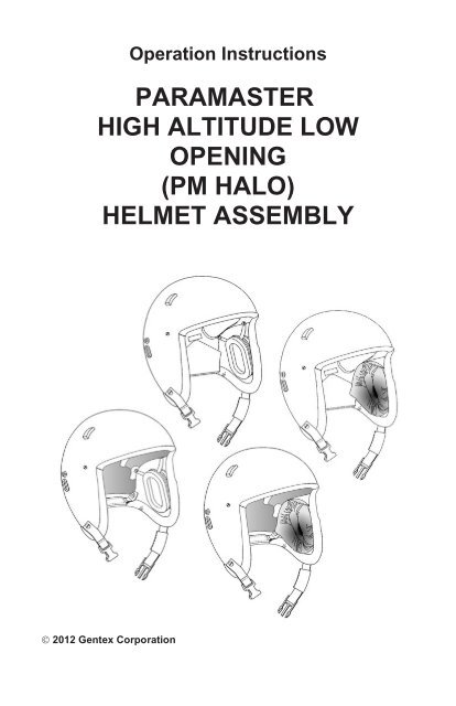
Operation InstructionsPARAMASTERHIGH ALTITUDE LOWOPENING(PM HALO)HELMET ASSEMBLY 2012 <strong>Gentex</strong> <strong>Corporation</strong>
ContentsSAFETY NOTICE . . . . . . . . . . . . . . . . . . . . . . . . . . . .iiDESCRIPTION . . . . . . . . . . . . . . . . . . . . . . . . . . . . . . 1Basic Helmet . . . . . . . . . . . . . . . . . . . . . . . . . . . . . . . . 2Optional Components . . . . . . . . . . . . . . . . . . . . . . . . . . . 4SYSTEM CHECKOUT AND OPERATION . . . . . . . . . . . . . . . 7Helmet Fit Check. . . . . . . . . . . . . . . . . . . . . . . . . . . . . . 7Attaching Snap-on Visor . . . . . . . . . . . . . . . . . . . . . . . . . 9Attaching Step-in Visor. . . . . . . . . . . . . . . . . . . . . . . . . . 10Stowing Helmet Communications Cable(Adjustable Pad Suspension Systems Only) . . . . . . . . . . . . . . 10Attaching Eye-protective Goggles SORZ and SKYEYES . . . . . . 11Operating Communications System . . . . . . . . . . . . . . . . . . 12Using Helmet Microphone with Down Lead Cable. . . . . . . . . . . . . . . 13Using 9" Mask Microphone Cable with Down Lead Cable . . . . . . . . . . 14Using 32" Mask Microphone Cable and Down Lead Cable with Switch . . . 16Using Ear-To-Ear Cable . . . . . . . . . . . . . . . . . . . . . . . . . . . . . 18INSPECTIONS . . . . . . . . . . . . . . . . . . . . . . . . . . . . . 21Preflight Inspection . . . . . . . . . . . . . . . . . . . . . . . . . 21Periodic Inspection . . . . . . . . . . . . . . . . . . . . . . . . . 22CLEANING . . . . . . . . . . . . . . . . . . . . . . . . . . . . . . . 24PARTS LISTS. . . . . . . . . . . . . . . . . . . . . . . . . . . . . . 26Basic Helmet . . . . . . . . . . . . . . . . . . . . . . . . . . . . . . . 26Optional Components . . . . . . . . . . . . . . . . . . . . . . . . . . 28Available Radio Adapters . . . . . . . . . . . . . . . . . . . . . . . . 31For installation and maintenance procedures, refer to technical manual TP0347,which is available at www.gentexcorp.com.i
SAFETY NOTICEWARNINGProper fitting, operation, and maintenance of the <strong>helmet</strong> isimperative for the safety of the user.Before you use the <strong>helmet</strong>, read this entire manual thoroughly.Follow all Warnings and Cautions precisely.ii
DESCRIPTIONThe Paramaster High Altitude Low Opening (PM HALO) Helmet Assembly(Figure 1) incorporates the latest materials and processes. The <strong>helmet</strong> islightweight, yet it affords maximum protection. It is also designed to provideunobstructed peripheral vision as well as ease of use with eye-protective goggles.The <strong>helmet</strong> conforms to Product Specification PS-0416 (effective February 2007)and has received safety confirmation from the U.S. Army TTC and the U.S. AirForce.The basic <strong>helmet</strong> includes a suspension system (adjustable pads or XLINER), aretention system, and earcups or leather earpads. Various optional componentsare available, including earphones, microphones, communications cables,alternative suspension systems, visors, goggles, and oxygen mask attachmenthardware. This allows users to equip their <strong>helmet</strong>s to fit their operational needs.This booklet includes a description of the basic <strong>helmet</strong> and optional componentsand includes instructions for general use and care. For installation andmaintenance procedures, refer to technical manual TP0347, which is availablefrom <strong>Gentex</strong> <strong>Corporation</strong> (www.gentexcorp.com).PART NUMBER 03D11801-1Medium/Large withadjustable padsand earcup retention<strong>assembly</strong>PART NUMBER 03D11801-2Medium/Large withadjustable padsand leather earpadsPART NUMBER 04D11905-1X-Large Wide with XLINERand earcup retention<strong>assembly</strong>PART NUMBER 04D11905-2X-Large Wide with XLINERand leather earpadsFigure 1. PM HALO Basic Helmet1
Basic HelmetAll basic <strong>helmet</strong>s (Figure 2, next page) include the following components:• Helmet shell. The outer surface of the <strong>helmet</strong> shell has a smooth finish(with non-reflective black paint) and is free of obstructions to preventsnagging of parachute lines. The <strong>helmet</strong> shell includes snaps forattachment of visors, bump stops to hold stowed visors in place, oblongeyelets though which goggle straps are threaded, pile fasteners to securethe goggle straps, and inside snaps for attachment of a communicationscable on either side of the <strong>helmet</strong>.• Edge roll. The leather-covered foam edge roll is reinforced in the frontand rear of the <strong>helmet</strong> to facilitate attachment of night vision goggle strapassemblies.• Chin strap. The chin strap is designed for a snug fit and <strong>helmet</strong> stability.It is attached to the <strong>helmet</strong> on both sides with attaching hardware.• Nape strap. The adjustable nape strap provides stability and a snug fit atthe back of the <strong>helmet</strong>.The differences among the basic <strong>helmet</strong>s are as follows:• Earcups. The <strong>helmet</strong> is supplied with one of two types of earcupsystems: the plastic earcup retention <strong>assembly</strong>, in which the earcupsare attached to the <strong>helmet</strong> shell with retention straps; or leather earpads,which attach to the inside of the <strong>helmet</strong> with hook and pile.• Suspension systems. The <strong>helmet</strong> is supplied with one of two types ofsuspension systems: the adjustable pad suspension system, whichprovides ease of fitting and air circulation; or the XLINER, which providesease of adjustment and simplified installation. Both systems are attachedto hook fasteners on the energy-absorbing liner inside the <strong>helmet</strong>.NOTE: If the <strong>helmet</strong> has an adjustable pad suspension system, the napestrap is laced through back of the rear pad. If the <strong>helmet</strong> has an XLINER,the nape strap has a nape pad.The table below shows these differences for each <strong>helmet</strong> part number.Helmet PartNumberSizeEarcupStyleSuspension Style03D11801-1 Medium/LargeEarcup RetentionAssemblyAdjustable Pads03D11801-2 Medium/Large Leather Earpads Adjustable Pads04D11905-1 X-Large WideEarcup RetentionAssemblyXLINER (1/2-inch thickX-Large Wide)04D11905-2 X-Large Wide Leather EarpadsXLINER (1/2-inch thickX-Large Wide)2
Bump stop*Visorsnap*Helmetshell*Energyabsorbingliner*Cable snap (inside <strong>helmet</strong>)*Cable snap(inside <strong>helmet</strong>)*Pile fastener*Oblongeyelet*Edge roll*Nape strap*Chin strap** Included on all <strong>helmet</strong>sAdjustable padsuspensionsystem03D11801-1Medium/LargeEarcupretention<strong>assembly</strong>04D11905-1X-Large WideRearpad03D11801-2Medium/LargeEarcupretention<strong>assembly</strong>RearpadXLINERNapepad04D11905-2X-Large WideLeatherearpadLeatherearpadXLINERNapepadAdjustable padsuspensionsystemFigure 2. Basic Helmet Components3
Optional ComponentsThe following optionalcomponents are available:• Flex boom <strong>helmet</strong>microphone(Figure 3). Availablein 150-ohm and5-ohm versions, themicrophone attachesto the <strong>helmet</strong> shellinterior with attachinghardware.• Earphones(Figure 4).Earphone optionsinclude 19-ohm,19-ohm waterproof,300-ohm, 600-ohm,1000-ohm waterproof,and 1200-ohmwaterproof.NOTE: For <strong>helmet</strong>swith leather earpads,earphones withattached cords arerequired.• Communicationscables (Figure 5).Options includecables for use withan oxygen maskmicrophone and/or a<strong>helmet</strong> microphone.NOTE: Cables with4-pin plugs are foruse with single radioadapters. Cables with5-pin plugs are foruse with dual radioadapters.(Continued on nextpage)Figure 3. MicrophoneDOWN LEAD CABLE 03C11797-2(Used with <strong>helmet</strong> microphone ormask microphone cable, 9" long)4-pin plug (single radio)MASK MICROPHONE CABLE, 9" long, 69C2080-3(Used with DOWN LEAD CABLE 03C11797-2 or -4)DOWN LEAD CABLE 03C11797-4(Similar to cable 03C11797-2, butwith 5-pin plug for dual radio adapters)5-pin plug (dual radio)DOWN LEAD CABLE WITH SWITCH 03C11797-6(Permits switching between <strong>helmet</strong> microphoneand oxygen mask microphone; used withmask microphone cable, 32" long)Switch4-pin plug (single radio)Figure 4. EarphonesMASK MICROPHONE CABLE, 32" long, 69C2080-4(Used with DOWN LEAD CABLE WITH SWITCH above)EAR-TO-EAR CABLE 03B11796-1(Used with oxygen mask communications cableor DOWN LEAD CABLE WITH SWITCH below)Switch4-pin plug (single radio)DOWN LEAD CABLE WITH SWITCH 06D12449-2Figure 5. Cables4
• Mask attachmentcomponents (Figure6). The following typesare available: fixedbayonet receivers,mask snap adaptors,and a low profilebayonet system. Eachtype is provided inpairs along withattaching hardware.• Suspension systems(Figure 7). Optionsinclude thethermoplastic liner(TPL), the adjustablepad suspension(included with theMedium/Large basic<strong>helmet</strong>s), and theXLINER (includedwith the X-Large Widebasic <strong>helmet</strong>s). Inaddition, the XLINER isavailable for both<strong>helmet</strong> sizes in1/2-inch and 3/4-inchthicknesses.• Nape pad (Figure 8).The leather-coveredfoam nape pad(included with X-LargeWide <strong>helmet</strong>s) isrequired for use withthe XLINER and theTPL.(Continued on next page)WARNINGIf an XLINER or a TPL isinstalled into a <strong>helmet</strong>,ensure that a nape pad isinstalled on the napestrap. Failure to do socould result in injury.XLINER and TPL are registeredtrademarks of <strong>Gentex</strong> <strong>Corporation</strong>.Fixed bayonetreceiver kitAnti-snag bayonetreceiver kitMask snap adapter kitFigure 6. Mask Attachment ComponentsTPLAdjustable padsuspensionAnti-snag bayonetreceiver kit, no receiversFigure 7. Suspension SystemsFigure 8. Nape PadXLINER5
• Snap-on visors(Figure 9). Snap-onvisors are snappeddirectly to the <strong>helmet</strong>.Visors are availablewith an MBU-12/Ptrim or an MBU-20/Ptrim and in clear orsunshade.• Visor cover(Figure 9). The visorcover protects thesnap-on visors in thestowed position. Thecover attachesto the visor withhook-and-pilefasteners.SunshadevisorClearvisorVisorcoverFigure 9. Snap-on Visors and Visor Cover• Step-in visor(Figure 10). Thestep-in visor isdesigned to be wornbetween the eyesand the night visiongoggles. Like thesnap-on visors, thestep-in visor issnapped directly tothe <strong>helmet</strong> and isavailable with anMBU-12/P trim or anMBU-20/P trim. Thestandard step-invisor is clear; aneodymium versionis also available.Figure 10. Step-in VisorModifiedSORZgoggle• Eye-protectivegoggles(Figure 11). Thefollowing types areavailable: themodified SORZ (withclear, sunshade, oramber lenses) andthe modifiedSKYEYES (with clearor sunshade lenses).Figure 11. Eye-protective GogglesModifiedSKYEYESgoggle6
SYSTEM CHECKOUT AND OPERATIONPerform system checkout to ensure that your <strong>helmet</strong> is in good operatingcondition. System checkout tasks include checking the fit of the <strong>helmet</strong>,performing an operational check of the communications system, attaching theoxygen mask and visors as required, and reporting any problems to yourmaintenance technician.Helmet Fit CheckCheck the fit of the <strong>helmet</strong>, keeping in mind the following WARNING andCAUTION notices.WARNING• Ensure that all <strong>helmet</strong> adjustment mechanisms are properly adjustedfor a snug, secure fit at all times when the <strong>helmet</strong> is worn. Failure todo so can result in an unstable <strong>helmet</strong> that will not protect the wearer.• If the <strong>helmet</strong> has an XLINER or a TPL, ensure that a nape pad isinstalled on the nape strap. Failure to do so could result in injury.CAUTIONWhen donning or doffing the <strong>helmet</strong>, flex the <strong>helmet</strong> just enough to allowsufficient clearance for the head. Excessive flexing may damage the<strong>helmet</strong>.NOTES:• Helmet size Medium/Large is designed to fit 85 percent of the population.Personnel with hat sizes 7-5/8 or larger may require <strong>helmet</strong> size X-LargeWide.• Figure 12 (next page) shows a <strong>helmet</strong> with an adjustable padsuspension system. However, this procedure also applies to <strong>helmet</strong>s withall other suspension systems (XLINER and TPL).1. Don the <strong>helmet</strong> as follows:a. Grip the <strong>helmet</strong> with thumbs hooked in the earcups (Figure 12, nextpage), and flex the <strong>helmet</strong> slightly to clear the head.b. Place the front edge of the <strong>helmet</strong> against the forehead.c. Rotate the <strong>helmet</strong> toward the rear and down onto the head. Ensure thatthe edgeroll is positioned just out of the aircrew member’s line of sightas the aircrew member looks upward.d. Allow the <strong>helmet</strong> to settle on the head for a few minutes before checkingthe fit.(Continued on next page)7
2. Adjust the nape strap (Figure 13)for a snug fit. Attach the end ofthe nape strap to the pilefastener.3. Buckle the chin strap (Figure 14)and adjust it for a snug fit. Attachthe end of the chin strap to thepile fastener on the chin pad.4. Evaluate the fit as follows:a. Overall <strong>helmet</strong> fit: The<strong>helmet</strong> should be snug andsecure, yet comfortable.Attempt to rock the <strong>helmet</strong>back and forth on your head,the <strong>helmet</strong> should not move.If you experience anyproblems with the overall fit,notify your maintenancetechnician.Figure 12. Grip forDonning Helmetb. Helmet height: Ensure thatthe edgeroll is just above theeyebrows; this is the correctheight. If the <strong>helmet</strong> is toohigh or too low, notify yourmaintenance technician.c. Earcup position: Ensurethat the earseals completelysurround the ears; this is thecorrect earcup position. Ifthe earcup position isincorrect, notify yourmaintenance technician.End of nape strapFigure 13. Nape StrapChin padBuckleEnd of chin strapFigure 14. Chin Strap8
Attaching Snap-on VisorReferring to Figure 15, do the following:1. Attach the visor by stretching the end of the strap slightly past the <strong>helmet</strong>snap and fastening the visor snap to the the <strong>helmet</strong> snap from front to back.Repeat for the other strap.2. Adjust the visor straps for a snug fit to the <strong>helmet</strong> by moving the slideadjustments as needed.3. Lower and raise the visor by grasping it in the middle, pulling it slightly awayfrom the <strong>helmet</strong>, and moving it down or up as needed. Ensure that the topedge of the visor is against the bump stops when the visor is raised.4. To remove the visor, grasp the end of the strap and pull it away from the<strong>helmet</strong> snap from back to front.5. If you are using the visor cover, do the following:a. Raise the visor.b. Attach the hook fasteners on the underside of the visor cover to the pilefasteners on the visor.Visor coverSlide adjustmentVisor snapPile fastenerBump stopHelmet snapFigure 15. Snap-on Visor9
Attaching Step-in Visor1. Don the <strong>helmet</strong>.2. Referring to Figure 16,do the following:a. Snap the step-invisor to the <strong>helmet</strong>on both sides.b. Adjust the strapsfor a snug fit bymoving the slideadjustments onboth sides.Slide adjustmentVisor snap3. Position the night visiondevice over the step-invisor.Helmet snapFigure 16. Step-in VisorStowing HelmetCommunications Cable(Adjustable PadSuspension SystemsOnly)Helmets with adjustablepad suspension system:Fold the cable and stow itunder the hook fastener tabon the back of the rearsuspension pad(Figure 17 ).Helmets with XLINER orTPL: Stow the cable insideyour clothing as directed byyour supervisor.CableHook fastenerFigure 17. Communications Cord Stowed10
AttachingEye-protectiveGoggles SORZand SKYEYES1. Before donning the<strong>helmet</strong>, insert thestrap ends throughthe slots in theback of the <strong>helmet</strong>(Figure 18) withthe goggle hangingloosely at the frontof the <strong>helmet</strong>.Figure 18. Straps Inserted Through Slots2. Don the <strong>helmet</strong>.3. Pulling the strapends furtherthrough the slots,bring the goggleinto place on theface until itfits snuglyas shown inFigure 19.Figure 19. Goggle in Place4. Attach the strapends to the pilefastener strip at theback of the <strong>helmet</strong>as shown inFigure 20.5. Stow the goggleatop the <strong>helmet</strong> asshown inFigure 21.Figure 20. Strap Ends AttachedFigure 21. Goggle Stowed11
Operating Communications SystemDepending on the communications components with which your <strong>helmet</strong> isequipped, shown in Figure 22, you will operate the communications system inone of the following ways:• Using the <strong>helmet</strong> microphone with the down lead cable. Refer to Page13.• Using the 9" oxygen mask microphone cable with the down lead cable.Refer to Pages 14-15.• Using the 32" oxygen mask microphone cable with the down leadcable with switch. Refer to Pages 16-17.• Using the ear-to-ear cable. Refer to Pages 18-20.Using<strong>helmet</strong>microphonewith downlead cableUsing9" maskmicrophonecable withdown leadcableUsing32" maskmicrophonecable withdown leadcable withswitchUsingear-to-earcable (canbe used inone ofthreeways)Figure 22. Helmet Communications Components12
Using Helmet Microphone with Down Lead CableEnsure that your maintenance technician has checked your communicationssystem with the testing device. With the <strong>helmet</strong> properly donned and fitted, andall straps properly fastened and adjusted, refer to Figure 23 and do the following:1. Don the <strong>helmet</strong>, adjust the nape strap, and fasten and adjust the chin strapas described on Pages 7 and 8.2. Bend the boom to adjust the microphone in front of your lips.3. Connect the down lead cable to your communications device.MicrophoneDown lead cableNOTE:Down lead cable with 4-pin plug (03C11797-2)is for use with single radio PTT adapters.Downlead cable with 5-pin plug (03C11797-4)is for use with dual radio PTT adapters.Refer to the cable adapter list at the end of thisbooklet for more information.To communications device4-pin plug (single radio)5-pin plug(dual radio)Figure 23. Microphone and Communications Cord13
Using 9" Mask Microphone Cable with Down Lead CableNOTE: Before you begin, ensure that the appropriate bayonet receiver kit isinstalled on your <strong>helmet</strong> and that the <strong>helmet</strong> and the oxygen mask have beenproperly fitted.1. Referring to Figure 24,unplug the <strong>helmet</strong>microphone from thecommunications cordconnector.2. Referring to Figure 25,stow the <strong>helmet</strong>microphone insidethe notch of theenergy-absorbing linerin the <strong>helmet</strong>.3. Referring to Figure 26,plug one end of the maskmicrophone cord into thedown lead cableconnector.Figure 24. Unplugging MicrophoneEnergy-absorbing linerDown lead cableconnectorMicrophoneMicrophoneplug4. If not already done, attachthe visor to the <strong>helmet</strong> asdescribed on Page 9.5. Don the <strong>helmet</strong>, adjust thenape strap, and fasten andadjust the chin strap asdescribed on Pages 7and 8.(Continued on next page)Figure 25. Microphone StowedInside HelmetDown lead cableconnectorMaskmicrophone cableDown leadcableFigure 26. Connecting Down Lead Cableto Mask Microphone Cable14
6. Referring to Figure 27,do the following:Visora. Attach the mask byinserting the maskbayonets into thebayonet receivers tothe fourth lockingposition.b. Lower the visor tocheck the interfacebetween the visorand the mask.BayonetBayonetreceiver7. Referring to Figure 28,do the following:Figure 27. Attaching Oxygen Maska. Plug the other end ofthe mask microphonecable to the oxygenmask microphone.b. Connect the downlead cable to yourcommunicationsdevice.NOTE:Down lead cable with4-pin plug (03C11797-2)is for use with single radioPTT adapters.Downlead cable with5-pin plug (03C11797-4)is for use with dual radioPTT adapters.Refer to the cable adapterlist at the end of thisbooklet for moreinformation.MaskmicrophoneMaskmicrophonecableDown lead cableTo communications device4-pin plug (single radio)5-pinplug(dualradio)Figure 28. Connecting Down Lead Cableto Mask Microphone15
Using 32" Mask Microphone Cable and Down Lead Cable with SwitchThis configuration allows you to switch from the <strong>helmet</strong> microphone to the oxygenmask microphone without unplugging the <strong>helmet</strong> microphone inside the <strong>helmet</strong>.Do the following:1. To use the <strong>helmet</strong> microphone (Figure 29):a. Don the <strong>helmet</strong>, adjust the nape strap, and fasten and adjust the chinstrap as described on Pages 7 and 8.b. Bend the boom to adjust the <strong>helmet</strong> microphone in front of your lips.c. Set the down lead cable switch to BOOM.d. Connect the down lead cable to your communications device.(Continued on next page)MicrophoneVIEW OFSWITCHDown lead cableNOTE: This down lead cable (03C11797-6) has a4-pin plug. Use this cable with single radio PTTadapters.Refer to the cable adapter list at the end of thisbooklet for more information.To communications device4-pin plug (single radio)16Figure 29. Using Helmet Microphone and Down Lead Cable with Switch
2. To use the maskmicrophone:a. Referring to Figure 30,stow the microphoneinside the <strong>helmet</strong>.b. Don the <strong>helmet</strong>, adjustthe nape strap, andfasten and adjust thechin strap as describedon Pages 7 and 8.c. Referring to Figure 31,connect one end of themask microphonecable to the receptacleon the down lead cableconnector.d. Referring to Figure 31,set the down leadcable switch to MASK.e. Attach the mask byinserting the maskbayonets into thebayonet receivers tothe fourth lockingposition. Lower thevisor to check theinterface between thevisor and the mask.f. Referring to Figure 31,connect the other endof the maskmicrophone cable tothe mask microphone.g. Connect the down leadcable to yourcommunicationsdevice.NOTE: This down leadcable (03C11797-6) has a4-pin plug. Use this cablewith single radio PTTadapters. Refer to thecable adapter list at theend of this booklet formore information.Figure 30. Microphone StowedInside HelmetMaskmicrophoneMaskmicrophonecableReceptacle ondown lead cableconnectorTo communications deviceMicrophoneFigure 31. Connecting Cordto Mask MicrophoneVIEW OFSWITCH17
Using Ear-To-Ear CableYou can use the ear-to-ear cable in one of the following ways: (1) with an oxygenmask that has its own communications cable, (2) with a down lead cable withswitch (06D12449-2) and a <strong>helmet</strong> microphone, or (3) with the same down leadcable and a 32" mask microphone cable. Do the following:1. To use the ear-to-ear cable with an oxygen mask that has its owncommunications cable (Figure 32):a. Don the <strong>helmet</strong>, adjust the nape strap, and fasten and adjust the chinstrap as described on Pages 7 and 8.b. Attach the mask by inserting the mask bayonets into the bayonetreceivers to the fourth locking position.c. Referring to Figure 32, connect the mask communications cable lead tothe ear-to-ear cable connector at the back of the <strong>helmet</strong>.(Continued on next page)Maskcommunicationscable leadEar-to-earcableBACK VIEWMaskcommunicationscable leadFigure 32. Using Helmet with Ear-to-Ear Cable18
2. To use the ear-to-ear cable with the down lead cable with switch and the<strong>helmet</strong> microphone (Figure 33):a. Don the <strong>helmet</strong>, adjust the nape strap, and fasten and adjust the chinstrap as described on Pages 7 and 8.b. Bend the boom to adjust the <strong>helmet</strong> microphone in front of your lips.c. Set the down lead cable switch to BOOM.d. Connect the down lead cable to your communications device.NOTE: This down lead cable (06D12449-2) has a 4-pin plug. Use this cablewith single radio PTT adapters. Refer to the cable adapter list at the end ofthis booklet for more information.(Continued on next page)MicrophoneVIEW OFSWITCHDown lead cableTo communications device4-pin plug (single radio)Figure 33. Using Helmet Microphone and Down Lead Cable with Switch19
3. To use the ear-to-ear cablewith the down lead cable withswitch and the 32" maskmicrophone cable:Microphonea. Referring to Figure 34,stow the microphoneinside the <strong>helmet</strong>.b. Don the <strong>helmet</strong>, adjustthe nape strap, andfasten and adjust thechin strap as describedon Pages 7 and 8.c. Referring to Figure 35,connect one end of the32" mask microphonecable to the receptacleon the down lead cableconnector.d. Referring to Figure 35,set the down lead cableswitch to MASK.e. Attach the mask byinserting the maskbayonets into thebayonet receivers to thefourth locking position.Lower the visor to checkthe interface betweenthe visor and the mask.f. Referring to Figure 35,connect the other end ofthe mask microphonecable to the maskmicrophone.g. Connect the down leadcable to yourcommunications device.NOTE: This down leadcable (06D12449-2) hasa 4-pin plug. Use thiscable with single radioPTT adapters. Refer tothe cable adapter list atthe end of this bookletfor more information.Figure 34. Microphone StowedInside HelmetMaskmicrophoneMaskmicrophonecableReceptacle ondown lead cableconnectorTo communications deviceFigure 35. Connecting Cordto Mask MicrophoneVIEW OFSWITCH20
INSPECTIONSPreflight, postflight, and periodic inspections are required to ensure that the<strong>helmet</strong> is in proper operating condition. The user shall perform preflightinspections. The maintenance technician shall perform postflight inspections(see technical manual TP0347). The user is responsible for ensuring that themaintenance technician has performed periodic inspections.Preflight InspectionPrior to each flight, the user shall inspect the <strong>helmet</strong> to determine that it is inserviceable condition and report any deficiencies to the maintenance technician.Do the following:1. Ensure that the <strong>helmet</strong>, earcups and oxygen mask are properly fitted.2. Check the <strong>helmet</strong> shell for evidence of damage such as cracks, warping, orchipped paint.NOTE: A hairline crack is defined as a fine crack which has broken the paintsurface, but has not necessarily broken through the layers of the <strong>helmet</strong>material. Any crack that has penetrated through the <strong>helmet</strong> material willaffect the integrity of the <strong>helmet</strong> and therefore the <strong>helmet</strong> should becondemned and disposed of.3. Ensure that the chin strap and nape strap are properly adjusted and thatthe screws are securely attached to the <strong>helmet</strong> shell.4. Ensure that the visors and goggles are free from cracks, scratches, dust,and smears. Minor scratches not interfering with the critical vision area arepermissible.5. Ensure that all communications components are securely attached andthat the headset/microphones operate properly. This check may beperformed by plugging the microphone cable and plug <strong>assembly</strong> intoMQ-1/MQ-1A tester, DMH-1, or service-approved tester. Speak into themicrophone. The microphone and earphones are operating properly whenthe voice is transmitted from the microphone through the amplifier and isheard in the headset.6. Check the energy absorbing liner and the suspension system (fittingpads, XLINER, or TPL) for looseness, improper fit, holes, cracks, or tornfabric.7. Check the general condition of all attaching hardware and components.8. Inspect the oxygen mask and associated components for general conditionas required by the applicable technical order.21
Periodic InspectionOperating personnel shall be responsible for ensuring that their <strong>helmet</strong>s havebeen inspected, cleaned and repaired as required by qualified equi<strong>pm</strong>enttechnicians within the last 30 days prior to each flight. Helmets that are notmanaged as integrated systems in conjunction with the oxygen mask may beinspected at a 90-day inspection interval. Inspections shall be annotated on asuitable inspection record, and suitable pressure sensitive-tape attached to the<strong>helmet</strong> or mask <strong>assembly</strong>, and/or as described by service directives.NOTE: As a result of this inspection, any component found to be defectivewill be repaired/replaced as necessary. Report any deficiencies to themaintenance technician.SERVICE OPTION: Helmets (with the oxygen mask) used very infrequentlyand carried on board the aircraft for emergency use, require inspection not toexceed 90 days. Services will determine what constitutes infrequently used(this should be specified service directives).1. Visually the inspect <strong>helmet</strong> shell for cleanliness, warping, holes, cracks andscratches.2. Inspect the leather edgeroll for holes, cuts, torn seams or detached areas.3. Inspect the bump stops for damaged and detached areas.4. Inspect the suspension system (fitting pads, XLINER, or TPL) as follows:a. Note how the suspension system is installed in the <strong>helmet</strong>; then removethe suspension system from the <strong>helmet</strong>.b. Examine the hook fasteners on the energy-absorbing liner, ensuring thatthe fasteners are securely adhered.c. Examine the energy-absorbing liner for damaged areas such as gouges,depressions, or evidence of erosion due to attack by solvents. Replacethe liner if there is reasonable assumption that head protection will becompromised due to the extent of liner damage.d. Examine the suspension system.Fitting pads: Examine for loosening of cemented parts (leather lining,pile backing, pile fasteners); torn fabric or seams; excessive soil.XLINER: Examine for torn fabric, separated seams, and excessive soil.Also, ensure that the XLINER is the correct size for the <strong>helmet</strong>.TPL (optional item): Inspect the cover for cleanliness and security ofattachment to the layers.(Continued on next page)22
5. Inspect the communications components as follows:a. Inspect the ear cushions for secure attachment to earcups, cleanliness,cuts, tears or evidence of compression set and hardening.b. Inspect earcups or leather earpads for breakage or other damage thatcould impair safety or sound attenuation.c. Inspect cords for breaks or frayed areas.d. Plug the microphone cable and plug <strong>assembly</strong> into the MQ-1/MQ-1A orDMH-1 tester and assure that the microphone and earphones areworking properly. Speak into the microphone. The microphone andearphones are operating properly when the voice is transmitted from themicrophone through the amplifier and heard in the headset.6. Inspect the visors and goggles as follows:NOTE: Visors and goggles are not required for altitude chamber studenttraining use.a. Inspect the straps to ensure that the nylon webbing and cotton elasticare not frayed or torn and that snap fasteners or hook/pile fasteners areall in good working condition.b. Visually inspect the visor snap fasteners for proper clinching of thefastener components.• The roll barrels in each snap socket and stud must be rolled over allaround. They should have a symmetrical, donut-shaped appearance.Any fastener on which the barrel material is not completely rolledover the edge of the stud or socket must be discarded.• Any roll with more than three splits that extend over the top of thebarrel and are readily detectable by visual observation shall beregarded as defective.c. Inspect the rubber edge beading at the top the visor lens for unbondedsections, cuts, tears, or holes.d. Inspect visor/goggle lens for cracks, scratches, dust particles andsmears. If visors are scratched, replace as necessary. Minor scratchesnot interfering with critical vision area are permissible.7. Inspect the nape strap and the chin strap for cleanliness and to ensure thatthe fabric and stitching are not frayed or torn; the buckles on the chin strapand the nape strap are not corroded, bent, or broken; the retainer screws inthe chin strap and the nape strap are securely attached and are notcorroded; and the washers are properly positioned.(Continued on next page)23
8. Inspect the bayonet receivers as follows:CAUTIONDo not use thread-locking adhesive on the bayonet receiver screws.The spacers will be damaged if they come into contact withthread-locking adhesive.a. Inspect the spacers for cracks or deterioration.b. Ensure that the screws are securely tightened and that the lock washersare installed.c. Ensure that the receivers were installed with the part number facing the<strong>helmet</strong> shell.9. Inspect the <strong>helmet</strong> visor snaps as follows:a. Inspect the snap screws for corrosion and tightness. Assure that the<strong>helmet</strong> is thoroughly cleaned and serviceable before returning to user.b. Check the snaps for security and proper installation of lock washer, partnumber MS35335–58.CLEANING1. Helmet Shell. Clean the <strong>helmet</strong> shell as follows:a. Wash the <strong>helmet</strong> shell using a mild detergent and a lint-free clothdampened with water. Mild abrasive scouring powder or soft-scrubbingcleanser may be used to remove stains or scuff marks.b. Wipe the <strong>helmet</strong> shell clean using a water-dampened cloth toremove detergents.2. Nape Strap Assembly. Clean the nape strap <strong>assembly</strong> as follows:a. Lightly sponge with a mild solution of detergent and water.b. Wipe with a damp, lint-free cloth.3. Adjustable Pad Suspension. Clean the adjustable pad suspension asfollows:a. Remove the pads from the <strong>helmet</strong>.b. Remove the foam pads from the covers.c. Hand wash the covers and foam pads and allow them to air dry.d. Reinstall the foam pads into the covers.e. Reinstall the adjustable pad suspension system into the <strong>helmet</strong>.f. Don the <strong>helmet</strong> and check the fit as described on Pages 7 and 8.(Continued on next page)24
4. TPL Assembly. Clean TPL <strong>assembly</strong> as follows:a. Remove the cloth cover from the plastic layer <strong>assembly</strong>.b. Clean the cover by hand washing with a mild solution of detergent andwater.c. Thoroughly rinse the cover in clear water and allow it to air dry.d. Apply new double-sided vinyl tape to the cover, and reinstall the coveron the plastic layer <strong>assembly</strong>.e. Reinstall the foam pads into the covers. Don the <strong>helmet</strong> and check thefit as described on Pages 7 and 8.5. XLINER. Clean the XLINER as follows:a. Remove the XLINER from the <strong>helmet</strong>.b. Hand-wash the XLINER with mild detergent; rinse thoroughly and allow todry flat. Observe the following precautions:• Do not place in dryer.• Do not wring.• Do not use bleach or machine detergents.c. Reinstall the XLINER.d. Don the <strong>helmet</strong> and check the fit as described on Pages 7 and 8.6. Communications Components. Wipe with a damp cloth.7. Visor Assemblies. Clean the visor assemblies with a soft, clean, lint-freecloth dampened with a 70 percent isopropyl alcohol solution or equivalent.8. Goggle Assemblies. Clean the goggle assemblies with a soft, clean clothdampened with water. Allow to air dry.9. Leather Edgeroll. Clean the leather edgeroll with a moistened gauze padand saddle soap to remove dirt. Rinse with a moist gauze pad and allow toair-dry.25
PARTS LISTSFollowing are the parts lists for the PM HALO <strong>helmet</strong>. Pages 26 and 27 showparts for the basic <strong>helmet</strong>. Pages 28-30 show optional components. Pages 31-35show available adapters For more information, contact <strong>Gentex</strong> <strong>Corporation</strong>, P.O.Box 315, Carbondale, PA 18407, phone (570)282-3550, fax (570)282-8555. Visitour web site at gentexcorp.com.Basic HelmetAdjustable padsuspensionEarcupretention<strong>assembly</strong>Nape strapChin strapChin padLeatherearpadFigure 36. PM HALO Basic Helmet, Medium/Large(For X-Large Wide, see Figure 37 on next page)Helmet Assembly, PM HALO,Medium/Large, with Plastic Earcups03D11801-1Earcup Retention Assembly03D11800-2 1 ea.Chin Strap09A12914-4 1 ea.Chin Pad89C7764-1 1 ea.Nape Strap03B11793-1 1 ea.Spacer Pad Set (Not shown)67B1721 1 ea.Adjustable Pad Suspension Kit02B11587-4 1 ea.Instruction BookletTP02571 ea.Helmet Assembly, PM HALO,Medium/Large, with Leather Earpads03D11801-2Leather Earpad Set79C4473-4 1 ea.Chin Strap09A12914-4 1 ea.Chin Pad89C7764-1 1 ea.Nape Strap03B11793-1 1ea.Spacer Pad Set (Not shown)67B1721 1 ea.Adjustable Pad Suspension Kit02B11587-4 1 ea.Instruction BookletTP02571 ea.26
XLINEREarcupretention<strong>assembly</strong>NapepadNape strapChin strapChin padLeatherearpadFigure 37. PM HALO Basic Helmet, X-Large Wide(For Medium/Large, see Figure 36 on previous page)Helmet Assembly, PM HALO,X-Large Wide, with Plastic Earcups04D11905-1Earcup Retention Assembly03D11800-2 1 ea.Chin Strap09A12914-4 1 ea.Chin Pad89C7764-1 1 ea.Nape Strap03B11793-1 1 ea.Nape Pad88C75031 ea.Spacer Pad Set (Not Shown)67B1721 1 ea.XLINER05D11925-7 1 ea.Instruction BookletTP02571 ea.Helmet Assembly, PM HALO,X-Large Wide, with Leather Earpads04D11905-2Earpad Set79C4473-4 1 ea.Chin Strap09A12914-4 1 ea.Chin Pad89C7764-1 1 ea.Nape Strap03B11793-1 1ea.Nape Pad88C75031 ea.Spacer Pad Set (Not Shown)67B1721 1 ea.XLINER05D11925-7 1 ea.Instruction BookletTP02571 ea.27
Optional ComponentsMicrophones (Figure 38)• Flex boom, 150-ohm:04B11827-1• Flex boom, 5-ohm:04B11827-2Earphones (Figure 39)• 19-ohm:69B2032• 19-ohm waterproof:73B2619• 300-ohm:75B3195• 600-ohm:78A3981• 1000-ohm waterproof:71B2383• 1200-ohm waterproof:90A7929Cables (Figure 40)• Down lead cable(single radio):03C11797-2(U-174/U connector)• Down lead cable(dual radio):03C11797-4(U-384/U connector)• Down lead cablewith switch:03C11797-6• Mask microphonecable, 9" long:69C2080-3• Mask microphonecable, 32" long:69C2080-4• Ear-to-ear cable:03B11796-1• Down lead cablewith switch:06D12449-2Continued on next pageFigure 38. MicrophoneFigure 39. EarphonesDOWN LEAD CABLE 03C11797-2(Used with <strong>helmet</strong> microphone ormask microphone cable, 9" long)4-pin plug (single radio)MASK MICROPHONE CABLE, 9" long, 69C2080-3(Used with DOWN LEAD CABLE 03C11797-2 or -4)DOWN LEAD CABLE 03C11797-4(Similar to cable 03C11797-2, butwith 5-pin plug for dual radio adapters)5-pin plug (dual radio)DOWN LEAD CABLE WITH SWITCH 03C11797-6(Permits switching between <strong>helmet</strong> microphoneand oxygen mask microphone; used withmask microphone cable, 32" long)Switch4-pin plug (single radio)MASK MICROPHONE CABLE, 32" long, 69C2080-4(Used with DOWN LEAD CABLE WITH SWITCH above)EAR-TO-EAR CABLE 03B11796-1(Used with oxygen mask communications cableor DOWN LEAD CABLE WITH SWITCH below)Switch4-pin plug (single radio)DOWN LEAD CABLE WITH SWITCH 06D12449-2Figure 40. Cables28
Oxygen Mask Receivers(Figure 41)• Glass beadedreceiver kit:82A5614-20• Fixed bayonetreceiver kit:93A8514• Mask snapadapter kit:91A8084-1• Anti-snag bayonet receiverkit:05A12024-2• Anti-snag bayonet receiverkit, no receivers:05A12024-1Suspension Systems(Figure 42)• TPL Kit, Medium/Large:85D7087-2P• TPL Kit, X-Large Wide:85D7087-30P• Adjustable PadSuspension:02B11599-2(Included withMedium/LargePM HALO Helmet)• XLINER, Medium/Large½" Thick:05D11925-3• XLINER, Medium/Large¾" Thick05D11925-4• XLINER, X-Large Wide½" Thick05D11925-7• XLINER, X-Large Wide¾" Thick:05D11925-8Nape Pad (Figure 43)• 88C7503Continued on next pageBayonet receiver kit(Glass beaded or fixed)Anti-snag bayonetreceiver kitFigure 41. Mask Attachment ComponentsTPLAdjustable padsuspensionFigure 42. Suspension SystemsFigure 43. Nape PadMask snap adapter kitAnti-snag bayonetreceiver kit, no receiversXLINER29
Snap-on Visors(Figure 44)• MBU-12/P TrimClear:81D5189-3• MBU-12/P TrimSunshade:81D5189-4• MBU-20/P TrimClear:91A8058-6• MBU-20/P TrimSunshade:91A8058-7• Visor cover85C7049-1Step-in Visors(Figure 45)• MBU-12/P trim,clear, Medium:01C11448-1• MBU-12/P trim,clear, Large/X-Large:01C11448-3• MBU-20/P trim,clear, Medium:01C11176-1• MBU_20/P trim,clear, Large/X-Large:01C11176-3Goggles (Figure 46)• SORZ (modified)Clear:03B11806-1• SORZ (modified)Sunshade:03B11806-2• SORZ (modified)Amber:03B11806-3• SKYEYES (modified)Clear:03B11805-1• SKYEYES (modified)Sunshade:03B11805-2SunshadevisorClearvisorFigure 44. Snap-on Visors and Visor CoverFigure 45. Step-in VisorsVisorcoverModifiedSORZgoggleModifiedSKYEYESgoggleFigure 46. Eye-protective Goggles30
Available Radio AdaptersAdapters are available for various aircraft and man-worn radios, including USAF,U.S. Army helos, PRC-148, SINGCARS, SABER, and others. Typical adaptersare shown in on Pages 31 through 35 . Contact <strong>Gentex</strong> <strong>Corporation</strong> for moreinformation.Single Radio Adapters (Figure 47)for use with downlead cables 03C11797-2 and 03C11797-6 (4-pin U-174/U)05B12186-2Lower cable with AMP and PTTfor Motorola HT 1000 radios05B12186-4Lower cable with PTTfor Motorola HT 1000 radios (no AMP)00D11022-1Lower cable with PTTand Urban MBITRwith remote finger PTT option00D11022-2Lower cable with PTTand Maritime MBITRwith remote finger PTT option07C12593-1Lower cable with PTTfor Motorola HT 1000 radioswith remote PTT option03C11762-1Lower cable with PTT for Saber Expo(6-pin connector)with remote PTT option07D12626-1Lower cable with PTTand Urban MBITR(no remote finger PTT option)07D12626-2Lower cable with PTTand Maritime MBITR(no remote finger PTT option)07D12626-3Lower cable with PTT;AP-107 connectorFigure 47. Single Radio Adapters for Cables 03C11797-2 and 03C11797-631
Single Radio Adapters (Figure 48)for use with downlead cable 03C11797-4 (5-pin U-384/U)05B12186-1Lower cable with AMP and PTTfor Motorola HT 1000 radios05B12186-3Lower cable with PTTfor Motorola HT 1000 radios (no AMP)04C11824-1Adapter U-385/U with PTT;connects to PRC-148 Urban MBITR;single radio only04C11824-2Adapter U-385/U with PTT;connects to PRC-148 Maritime MBITR;single radio only05C12231-1Lower cable with PTTand remote PTT;accepts U-384 to Urban MBITR05C12231-2Lower cable with PTTand remote PTT;accepts U-384 to Maritime MBITR05C12231-3Lower cable with PTTand remote PTT;accepts U-384 to AP10707C12593-1Lower cable with PTTand remote PTT optionfor Motorola HT 1000 radios00B11020-1Remote finger PTTwith single-button ON/OFFFigure 48. Single Radio Adapters for Cable 03C11797-432
Dual Radio Adapters (Figure 49)for use with downlead cable 03C11797-4 (5-pin U-384/U)02C11626-1Lower cable with dual PTT03C11699-1Lower cable with dual PTT(interfaces with remote PTT)03B11700-1Remote dual radio PTTwith two buttonsFigure 49. Dual Radio Adapters for Cable 03C11797-4Dual Radio Adapters (Figure 50)for use with lower cable 03C11699-1 or 02C11626-1 (dual radio PTT)03C11719-1Adapter for Urban MBITR PRC-148;extends 2 feet03C11719-2Adapter for Urban MBITR PRC-148;extends 4 feet01B11428-1Adapter for Maritime MBITR PRC-14801B11429-1Adapter for AIC-10 intercom07C12592-1Adapter with pre-ampfor Motorola HT 1000 radios97D9975-6Adapter for Motorola HT 1000 radios06C12301-2Adapter with pre-amp that convertsAJ107 to U-174/UFigure 50. Dual Radio Adapters for Cable 03C11699-1 or 02C11626-133
Specialty Adapters (Figure 51)05B12197-1Adapter that converts 4-pin U-174/Uto 5-pin U-385/U05B12197-2Adapter with pre-amp that converts4-pin U-174/U to 5-pin U-385/U06C12301-1Adapter with pre-amp that converts5-pin U-384/U to 4-pin U-174/U06C12301-3Adapter with pre-amp that convertsU-384/U to U-385/U09C13036-1Extension cable that convertssingle U-384/U to dual U-385/U09C13037-1Extension cable that convertsU-384/U to U-385/U00B11046-1Adapter that converts 5-pin U-384/Uto 4-pin U-174/U on cable 03C11797-4Figure 51. Specialty AdaptersCables Wired for Peltor PTT Assemblies (Figure 52)06D12539-2Upper cable with U-174/Usimilar to 03C11797-206D12539-4Upper cable with TPSJ-101similar to 03C11797-63406D12538-2Upper cable with TPSJ-101similar to 06D12449-2Figure 52. Cables for Peltor PTT
Breakaway Cables (Figure 53)08A12803-1Breakaway version of 03C11797-208A12803-2Breakaway version of 03C11797-408A12803-3Breakaway version of 03C11797-6Figure 53. Breakaway Cables35
TP0257 REV. 4 FEBRUARY 2012