POS/MV Description and Theory of Operation prepared ... - Applanix
POS/MV Description and Theory of Operation prepared ... - Applanix
POS/MV Description and Theory of Operation prepared ... - Applanix

You also want an ePaper? Increase the reach of your titles
YUMPU automatically turns print PDFs into web optimized ePapers that Google loves.
<strong>POS</strong>/LV<br />
Training Guide<br />
<strong>prepared</strong> by<br />
<strong>Applanix</strong> Corporation<br />
85 Leek Crescent<br />
Richmond Hill, Ontario, L4B 3B3<br />
Tel: (905) 709-4600 Fax: (905) 709-6027<br />
Web: www.applanix.com E-Mail: support@applanix.com<br />
www.applanix.com Integrated Inertial GPS Solutions Copyright ©2000 <strong>Applanix</strong><br />
Corporation
Scope<br />
This tutorial focuses on <strong>POS</strong>/LV theory <strong>and</strong> operation.<br />
Subjects to be addressed:<br />
• What is <strong>POS</strong>/LV?<br />
• What does <strong>POS</strong>/LV do?<br />
• Benefits <strong>of</strong> <strong>POS</strong>/LV over other Motion Sensors<br />
• <strong>POS</strong>/LV <strong>Theory</strong> <strong>of</strong> <strong>Operation</strong><br />
• <strong>POS</strong>/LV Performance Specifications<br />
• <strong>POS</strong>/LV System Overview<br />
• Generating Navigation Data using <strong>POS</strong>/LV<br />
www.applanix.com Integrated Inertial GPS Solutions Copyright ©2000 <strong>Applanix</strong><br />
Corporation
Introducing <strong>POS</strong>/LV<br />
www.applanix.com Integrated Inertial GPS Solutions Copyright ©2000 <strong>Applanix</strong><br />
Corporation
<strong>POS</strong>/LV is:<br />
What is <strong>POS</strong>/LV?<br />
• an Aided Inertial Navigation System<br />
• configured for l<strong>and</strong>-based surveys <strong>and</strong> terrestrial remote sensing<br />
<strong>POS</strong>/LV includes:<br />
• <strong>POS</strong> computer system (PCS) – Computational heart <strong>of</strong> the system<br />
• Inertial measurement unit (IMU) - Contains 3 gyros, 3 accelerometers<br />
<strong>and</strong> related electronics<br />
• Distance Measurement Indicator (DMI) - A distance sensor that mounts<br />
to one <strong>of</strong> the vehicle’s wheels.<br />
• Primary GPS receiver - a dual frequency receiver within the PCS<br />
• Secondary GPS receiver - a single frequency receiver for use with the<br />
GPS Azimuth Measurement Subsystem (GAMS)<br />
www.applanix.com Integrated Inertial GPS Solutions Copyright ©2000 <strong>Applanix</strong><br />
Corporation
What Does <strong>POS</strong>/LV Do?<br />
• <strong>POS</strong>/LV was designed to provide a complete<br />
integrated solution for the measurement <strong>of</strong>:<br />
• position (latitude, longitude, altitude)<br />
• velocity (North, East, Down components)<br />
• orientation (roll, pitch, heading)<br />
• rates (acceleration, angular rate)<br />
• <strong>POS</strong>/LV thus replaces the following equipment:<br />
• vertical gyro or roll/pitch gyro<br />
• heading sensor (compass or directional gyro)<br />
• GPS receiver<br />
• distance measuring instrument<br />
• data integration <strong>and</strong> collation computer<br />
• <strong>POS</strong>/LV provides a highly accurate navigation<br />
solution in real-time or with post-processing<br />
www.applanix.com Integrated Inertial GPS Solutions Copyright ©2000 <strong>Applanix</strong><br />
Corporation
What Does <strong>POS</strong>/LV Do?<br />
• Provides Aided Inertial Navigation Solution<br />
Time (UTC or GPS seconds <strong>of</strong> the week)<br />
Position (latitude, longitude, altitude)<br />
Velocity (North, East, Down components), track, <strong>and</strong> speed<br />
3-axis attitude (roll, pitch, heading)<br />
• Records navigation <strong>and</strong> sensor data to PC Card for post-processing<br />
• Monitors <strong>and</strong> reconfigures sensors for best solution<br />
• Operates St<strong>and</strong> Alone or with PC s<strong>of</strong>tware monitoring<br />
• AutoStart<br />
<strong>POS</strong>/LV startup/operation without user input<br />
• AutoRecovery<br />
<strong>POS</strong>/LV to recover from IMU/PCS comm. errors<br />
• Event Tagging<br />
Records event time<br />
www.applanix.com Integrated Inertial GPS Solutions Copyright ©2000 <strong>Applanix</strong><br />
Corporation
PC Card<br />
What Does <strong>POS</strong>/LV Do?<br />
<strong>POS</strong>/LV Outputs<br />
• User-selectable raw sensor <strong>and</strong> navigation data<br />
• Compatible with Type I PC Flash cards<br />
Ethernet Data Port<br />
• User-selectable raw sensor <strong>and</strong> navigation data<br />
• Variable output rate – up to 200 Hz<br />
Serial Port<br />
• NMEA message output – up to 7 messages at 50Hz<br />
www.applanix.com Integrated Inertial GPS Solutions Copyright ©2000 <strong>Applanix</strong><br />
Corporation
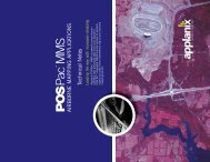
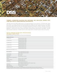
Primary <strong>and</strong> Secondary GPS Antennas<br />
Mobile Component<br />
DMI<br />
Recorded<br />
<strong>POS</strong> Data<br />
GPS Base<br />
Station Data<br />
IMU<br />
GPS Base Station<br />
GPS base receiver<br />
survey instrument mounted<br />
on (gimballed) platform<br />
Forward Pass<br />
(Kalman Filter)<br />
<strong>POS</strong>/LV <strong>and</strong> <strong>POS</strong>Pac<br />
Vehicle Body<br />
PCS<br />
Real-time differential GPS<br />
corrections (optional)<br />
Post-Processing<br />
Component<br />
Data retrieval Post-processing<br />
Backward Pass<br />
(Optimal<br />
Smoother)<br />
• <strong>POS</strong>Pac post-processes<br />
recorded <strong>POS</strong> data<br />
• Generates accurate Best<br />
Estimate <strong>of</strong> Trajectory (BET)<br />
• Sensor positions <strong>and</strong> attitude<br />
angles are interpolated from<br />
BET<br />
Best Estimate<br />
<strong>of</strong> Trajectory<br />
(BET)<br />
www.applanix.com Integrated Inertial GPS Solutions Copyright ©2000 <strong>Applanix</strong><br />
Corporation
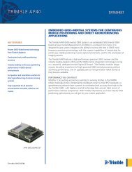
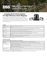
Advantages <strong>of</strong> Post-Processing<br />
Post-processing<br />
• Can provide a dramatic improvement in navigation accuracy<br />
• Especially helpful with poor GPS / GPS dropouts<br />
Simulated Real-Time Solution Post-Processed BET Solution<br />
www.applanix.com Integrated Inertial GPS Solutions Copyright ©2000 <strong>Applanix</strong><br />
Corporation
<strong>POS</strong>/LV Technology Heritage<br />
<strong>POS</strong> technology evolved from Aided Inertial Navigation<br />
technology used in military aircraft since the late 1960’s<br />
Helicopter Integrated<br />
Navigation System (HINS)<br />
1986-91<br />
<strong>POS</strong>/LV<br />
Present<br />
www.applanix.com Integrated Inertial GPS Solutions Copyright ©2000 <strong>Applanix</strong><br />
Corporation
Benefits <strong>of</strong> <strong>POS</strong>/LV over other Sensors<br />
<strong>POS</strong>/LV vs. GPS Only<br />
GPS Receivers<br />
• 1Hz position samples<br />
• 90 km/h vehicle speed = 25 meter sample interval<br />
<strong>POS</strong>/LV<br />
• Up to 200 Hz data samples<br />
• 90 km/h vehicle speed = 12.5cm sample interval<br />
• Blending GPS data with Inertial <strong>and</strong> DMI data reduces GPS noise<br />
• Inertial component fills in data between GPS position samples or<br />
during outages<br />
www.applanix.com Integrated Inertial GPS Solutions Copyright ©2000 <strong>Applanix</strong><br />
Corporation
<strong>POS</strong>/LV <strong>Theory</strong> <strong>of</strong> <strong>Operation</strong><br />
How Does <strong>POS</strong>/LV Work?<br />
www.applanix.com Integrated Inertial GPS Solutions Copyright ©2000 <strong>Applanix</strong><br />
Corporation
Computing Roll or Pitch Using an<br />
Accelerometer<br />
Accelerometers<br />
• Sense Gravity<br />
• Measure long-term roll <strong>and</strong> pitch<br />
Calculations<br />
• With no accelerations, pitch<br />
angle equals<br />
θ = arcsin(as/g)<br />
• Roll angle is computed in the<br />
same manner<br />
sensed acceleration<br />
as = g cos(θ)<br />
This method is subject to short-term errors, <strong>and</strong> cannot be used by itself<br />
accelerometer<br />
input axis<br />
gravity = g<br />
www.applanix.com Integrated Inertial GPS Solutions Copyright ©2000 <strong>Applanix</strong><br />
Corporation<br />
pitch angle θ
<strong>POS</strong> Aided Inertial Navigation Algorithm<br />
Aided Inertial Navigation System<br />
• Blends IMU <strong>and</strong> aiding sensor data<br />
• Outputs position <strong>and</strong> orientation<br />
Accelerometers<br />
Gyros<br />
IMU<br />
(D)GPS<br />
DMI<br />
GAMS<br />
Strapdown<br />
navigator<br />
Feedback<br />
error controller<br />
Kalman<br />
filter<br />
Navigator<br />
corrections<br />
Filter Estimated<br />
corrections errors<br />
Blended<br />
navigation<br />
solution<br />
www.applanix.com Integrated Inertial GPS Solutions Copyright ©2000 <strong>Applanix</strong><br />
Corporation
2 functions<br />
• Estimation<br />
Kalman Filter<br />
Estimates noise based on sensor data <strong>and</strong> system modeling<br />
• Noise Reduction<br />
Adjusts navigation solution once per second using error estimate<br />
System<br />
Internal dynamics<br />
Kalman<br />
Filter<br />
www.applanix.com Integrated Inertial GPS Solutions Copyright ©2000 <strong>Applanix</strong><br />
Corporation<br />
Output<br />
Estimated<br />
internal<br />
dynamics
Sensor Noise<br />
• Properties differ between<br />
sensor types<br />
GPS = broadb<strong>and</strong><br />
Inertial = low frequency<br />
Eliminating Noise<br />
• Inertial <strong>and</strong> GPS errors can<br />
be separated<br />
• Complementary filter uses<br />
GPS + Inerial error sum to<br />
reset Inertial position data<br />
Continuity<br />
• Inertial data fills GPS gaps<br />
• Solution is continuous<br />
Sensor Blending<br />
INS position error<br />
GPS position error<br />
www.applanix.com Integrated Inertial GPS Solutions Copyright ©2000 <strong>Applanix</strong><br />
Corporation<br />
INS<br />
1 nmi 20 m<br />
20 m<br />
Blended North position error<br />
Rtrue + ∆RINS<br />
+<br />
-<br />
1 nmi<br />
INS-GPS position difference<br />
Low-pass filter<br />
1 nmi<br />
-<br />
+<br />
Rtrue + ∆RAPS<br />
∆RINS - ∆RAPS<br />
Filtered INS-GPS position difference<br />
APS<br />
GPS<br />
depth<br />
sensor
<strong>POS</strong>/LV Performance<br />
Specifications<br />
www.applanix.com Integrated Inertial GPS Solutions Copyright ©2000 <strong>Applanix</strong><br />
Corporation
Post-Processed Solution<br />
• The solution is updated at 200Hz.<br />
• Accuracies with GPS (values for <strong>POS</strong>/LV 420):<br />
Quantity With Carrier Phase DGPS *<br />
Position 0.03m (1)<br />
Velocity 0.005 m/s<br />
Roll <strong>and</strong> Pitch 0.005 degrees<br />
Heading 0.02 degrees<br />
1 dependent on type <strong>of</strong> DGPS solution (float vs fixed<br />
integer carrier phase)<br />
* all values RMS per axis<br />
www.applanix.com Integrated Inertial GPS Solutions Copyright ©2000 <strong>Applanix</strong><br />
Corporation
<strong>POS</strong>/LV System Overview<br />
www.applanix.com Integrated Inertial GPS Solutions Copyright ©2000 <strong>Applanix</strong><br />
Corporation
<strong>POS</strong>/LV 420 includes:<br />
System Overview<br />
• <strong>POS</strong> computer system (PCS)<br />
• Inertial measurement unit (IMU)<br />
• Distance Measurement Indicator (DMI)<br />
• 2 GPS receivers<br />
• Windows Controller s<strong>of</strong>tware<br />
<strong>POS</strong>/LV 420 modes <strong>of</strong> operation:<br />
St<strong>and</strong>by<br />
Navigate<br />
• No navigation solution output<br />
• Only raw sensor data<br />
• Normal mode <strong>of</strong> operation<br />
• Navigation solution output<br />
www.applanix.com Integrated Inertial GPS Solutions Copyright ©2000 <strong>Applanix</strong><br />
Corporation
<strong>POS</strong> Computer System<br />
• Size 350 x 445 x 111 mm<br />
2.5U, 19” rack mount compatible<br />
• Power 120/220 VAC, 60/50Hz, 110W max.<br />
• Weight 9.4 kg<br />
• Temperature 0 o to +50 o C<br />
• Humidity 5% to 95% RH non-condensing<br />
• Components Power supplies<br />
Communication processor<br />
Navigation processor<br />
Serial interface module<br />
Ethernet interface<br />
Timing <strong>and</strong> synchronization hardware<br />
GPS receivers (L1 <strong>and</strong> L1/L2)<br />
www.applanix.com Integrated Inertial GPS Solutions Copyright ©2000 <strong>Applanix</strong><br />
Corporation
Inertial Measurement Unit<br />
• Gyros fiber optic gyros<br />
• Accelerometers silicon accelerometers<br />
• Data Output Incremental velocities <strong>and</strong> angles (∆V, ∆θ)<br />
• Data Rate 200 Hz<br />
• Data Interface Serial digital<br />
• Size 204 x 204 x 168 mm<br />
• Weight 3.5 kg<br />
• Temperature -40 o to +60 o C<br />
• Power From <strong>POS</strong> computer system<br />
www.applanix.com Integrated Inertial GPS Solutions Copyright ©2000 <strong>Applanix</strong><br />
Corporation
GPS Receivers<br />
<strong>POS</strong>/LV contains one each <strong>of</strong> the following embedded GPS<br />
receivers:<br />
L1/L2 GPS receiver<br />
• dual frequency<br />
• 12 channel<br />
• RT-2 option available (narrow lane RTK)<br />
High Performance L1 GPS receiver<br />
• single frequency receiver<br />
• 12 channels<br />
• very accurate code <strong>and</strong> phase tracking<br />
www.applanix.com Integrated Inertial GPS Solutions Copyright ©2000 <strong>Applanix</strong><br />
Corporation
Distance Measurement Indicator (DMI)<br />
• Size 153 mm diameter x 97mm (not including collets or<br />
restraint rod)<br />
• Weight 2.7 kg<br />
• Temperature -40 o to +80 o C<br />
• Humidity 0 to 100%<br />
High resistance to shock<br />
www.applanix.com Integrated Inertial GPS Solutions Copyright ©2000 <strong>Applanix</strong><br />
Corporation
<strong>POS</strong>/LV<br />
Summary<br />
• Complete source <strong>of</strong> real-time or post-processed position <strong>and</strong><br />
orientation data<br />
• Replaces<br />
roll/pitch sensor (vertical gyro)<br />
heading sensor (directional gyro)<br />
GPS receiver<br />
distance measuring instrument (DMI)<br />
data integration, collation <strong>and</strong> recording computer<br />
• Provides excellent performance in a high dynamic environment<br />
• Provides data continuity during GPS outages<br />
• Provides highly accurate solution when used with <strong>POS</strong>Pac<br />
www.applanix.com Integrated Inertial GPS Solutions Copyright ©2000 <strong>Applanix</strong><br />
Corporation
Generating Navigation Data<br />
using <strong>POS</strong>/LV<br />
www.applanix.com Integrated Inertial GPS Solutions Copyright ©2000 <strong>Applanix</strong><br />
Corporation
Generating Navigation Data<br />
using <strong>POS</strong>/LV<br />
Five Steps:<br />
1) Plan Mission<br />
2) Drive Mission: Collect raw data using <strong>POS</strong>/LV<br />
3) Extract Data: PosPac Extraction Utility<br />
4) Generate differential GPS solution: PosGPS<br />
5) Generate SBET navigation solution: PosProc<br />
www.applanix.com Integrated Inertial GPS Solutions Copyright ©2000 <strong>Applanix</strong><br />
Corporation
Step 1<br />
Plan Mission<br />
www.applanix.com Integrated Inertial GPS Solutions Copyright ©2000 <strong>Applanix</strong><br />
Corporation
Step 1: Mission Planning<br />
Plan as for a st<strong>and</strong>ard DGPS survey:<br />
• Minimize baseline length(
Minimize Baseline Length<br />
Carrier Phase DGPS Accuracy Limitations<br />
• Receiver Noise (~2 cm)<br />
• Multipath<br />
• Baseline Effect (Atmospheric Delays)<br />
Baseline Effects<br />
• 1 to 2 ppm (1-2mm per km)<br />
• Up to 5 ppm during peak <strong>of</strong> solar cycle<br />
Baseline
Multipath<br />
Minimize Multipath<br />
• Caused by reflections <strong>of</strong> GPS signals<br />
• Error can be as large as 1-2 m<br />
Base Stations away from <strong>and</strong> above reflective<br />
surfaces<br />
Use Choke Rings on antennas<br />
www.applanix.com Integrated Inertial GPS Solutions Copyright ©2000 <strong>Applanix</strong><br />
Corporation
Minimize DOP<br />
DOP (dilution <strong>of</strong> precision)<br />
• Reduced accuracy due to satellite position<br />
• Acts as scale factor for position error<br />
(e.g. if DOP = 7 , 5 cm error becomes 35 cm)<br />
Plan mission to run during maximum satellite coverage to<br />
obtain best data<br />
Redundancy<br />
Multiple Base Stations<br />
www.applanix.com Integrated Inertial GPS Solutions Copyright ©2000 <strong>Applanix</strong><br />
Corporation
Step 2<br />
Drive Mission<br />
www.applanix.com Integrated Inertial GPS Solutions Copyright ©2000 <strong>Applanix</strong><br />
Corporation
Step 2: Drive Mission<br />
Using <strong>POS</strong>/LV effectively:<br />
• Proper installation<br />
• Proper h<strong>and</strong>ling<br />
www.applanix.com Integrated Inertial GPS Solutions Copyright ©2000 <strong>Applanix</strong><br />
Corporation
Installation Parameters<br />
Installation Data input into <strong>POS</strong> via LV-<strong>POS</strong>View<br />
Entered once <strong>and</strong> saved into memory<br />
Three types <strong>of</strong> parameters<br />
• Lever Arms<br />
• Misalignment Angles<br />
• GAMS Orientation<br />
www.applanix.com Integrated Inertial GPS Solutions Copyright ©2000 <strong>Applanix</strong><br />
Corporation
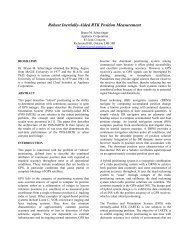
Lever Arms<br />
X, Y, Z distances between two body frames<br />
For Lever Arm measurements:<br />
• X is positive towards front <strong>of</strong> vehicle<br />
• Y is positive towards right side <strong>of</strong> vehicle<br />
• Z is positive down through bottom <strong>of</strong> vehicle<br />
www.applanix.com Integrated Inertial GPS Solutions Copyright ©2000 <strong>Applanix</strong><br />
Corporation
Se c ond a ry GPS Ante nna<br />
Re fe re nc e bodyframe<br />
IMUle ve r a rm<br />
IMUbody fra me<br />
GAMS Baseline Vector<br />
Lever Arms<br />
GPSlever a rm<br />
Primary GPSAntenna<br />
Se nsor le ve r a rm<br />
DMIleverarm<br />
Se nsor bodyframe<br />
Instrum e nte d Whe e l<br />
www.applanix.com Integrated Inertial GPS Solutions Copyright ©2000 <strong>Applanix</strong><br />
Corporation
• Reference to GPS<br />
Lever Arms<br />
To translate GPS position <strong>and</strong> velocity data to centre <strong>of</strong><br />
Reference frame<br />
• Reference to IMU<br />
To translate IMU position <strong>and</strong> velocity data to centre <strong>of</strong><br />
Reference frame<br />
• Reference to DMI<br />
To translate DMI distance data to centre <strong>of</strong> Reference<br />
frame<br />
All <strong>POS</strong> position <strong>and</strong> velocity outputs are valid at centre <strong>of</strong><br />
Reference frame<br />
www.applanix.com Integrated Inertial GPS Solutions Copyright ©2000 <strong>Applanix</strong><br />
Corporation
Lever Arms<br />
Real-time Accuracy: 10 - 20cm<br />
Post-processed: User to GPS: 10 - 20 cm*<br />
* are refined by PosProc<br />
User to IMU: 1 - 3 cm<br />
www.applanix.com Integrated Inertial GPS Solutions Copyright ©2000 <strong>Applanix</strong><br />
Corporation
• Sequence <strong>of</strong> rotations<br />
to align one body<br />
frame with another<br />
• e.g. IMU body frame<br />
with respect to<br />
Reference body frame<br />
Misalignment Angles<br />
www.applanix.com Integrated Inertial GPS Solutions Copyright ©2000 <strong>Applanix</strong><br />
Corporation<br />
X<br />
Y<br />
X<br />
Z<br />
IMU body frame<br />
Y<br />
Y<br />
Z<br />
X<br />
Re fe re nce body fra me<br />
Z
• Reference to IMU<br />
Misalignment Angles<br />
To translate IMU attitude data to centre <strong>of</strong> Reference<br />
frame<br />
• Vehicle to Reference<br />
To translate data from Reference to Vehicle frame<br />
(usually 0 – frames aligned)<br />
www.applanix.com Integrated Inertial GPS Solutions Copyright ©2000 <strong>Applanix</strong><br />
Corporation
Reference to IMU<br />
Misalignment Angles<br />
• Angles determined during installation<br />
• Dependant upon IMU type, IMU location <strong>and</strong> sensor type<br />
Vehicle to Reference<br />
• Angles usually set to zero<br />
www.applanix.com Integrated Inertial GPS Solutions Copyright ©2000 <strong>Applanix</strong><br />
Corporation
Misalignment Angles<br />
Real-time Accuracy: 10 deg<br />
Post-processed: User to IMU: 10 deg*<br />
Vehicle to User: 10 deg*<br />
* Refined by boresighting program PosBST<br />
www.applanix.com Integrated Inertial GPS Solutions Copyright ©2000 <strong>Applanix</strong><br />
Corporation
GAMS Orientation<br />
<strong>POS</strong>/LV will determine antenna separation vector<br />
automatically during GAMS configuration<br />
www.applanix.com Integrated Inertial GPS Solutions Copyright ©2000 <strong>Applanix</strong><br />
Corporation
Mission Checklists<br />
www.applanix.com Integrated Inertial GPS Solutions Copyright ©2000 <strong>Applanix</strong><br />
Corporation
Data Storage<br />
Considerations<br />
� To maximize storage space, you can reduce the real-time output to 10 Hz;<br />
raw data rate (200 Hz IMU <strong>and</strong> 2 Hz GPS) are unaffected by this change!<br />
� A 1GB PC Card will hold approximately 4 hours <strong>of</strong> data.<br />
� Quick-Format PC Cards before the mission to erase all files (incl. Recycle<br />
Bin)<br />
www.applanix.com Integrated Inertial GPS Solutions Copyright ©2000 <strong>Applanix</strong><br />
Corporation
Mission Preparation<br />
� Bring several PC Cards <strong>and</strong> store them appropriately until use<br />
� Check laptop PC battery for good charge<br />
� Enter mission data in <strong>POS</strong>/LV Mission Pr<strong>of</strong>ile Form (see <strong>Operation</strong> Guide)<br />
� Check all cables for secure connections<br />
� Check Event cable for connection if Event timing is being used<br />
www.applanix.com Integrated Inertial GPS Solutions Copyright ©2000 <strong>Applanix</strong><br />
Corporation
Mission Start Checklist<br />
� Power on all equipment – verify that no errors present<br />
� Park vehicle away from buildings <strong>and</strong> other multipath reflection sources<br />
� Switch <strong>POS</strong>/LV to Navigate mode – wait for GPS Status:OK <strong>and</strong> Coarse<br />
Leveling to finish<br />
� Insert PC Card in drive<br />
� Click Start Logging in PC Card Logging window<br />
� If using Events, trigger sensor – verify increasing event count<br />
� Ensure that DGPS Base Station is on<br />
� Log 5-10 minutes <strong>of</strong> data<br />
� Start mission. Watch for <strong>POS</strong> LED to turn solid green within 5 minutes<br />
www.applanix.com Integrated Inertial GPS Solutions Copyright ©2000 <strong>Applanix</strong><br />
Corporation
St<strong>and</strong> Alone Mode<br />
During Mission Checklist<br />
� Monitor <strong>POS</strong>/LV using PCS status LEDs<br />
� Use DATA LOG button to start/stop data logging to PC Card<br />
Controller Monitor Mode<br />
� Monitor LV-<strong>POS</strong>View Main Window displays – compare to vehicle motion<br />
� Monitor LV-<strong>POS</strong>View Faults Window<br />
� Monitor Events count in LV-<strong>POS</strong>View Main Window – compare to sensor<br />
www.applanix.com Integrated Inertial GPS Solutions Copyright ©2000 <strong>Applanix</strong><br />
Corporation
During Mission Restart<br />
� Stop vehicle away from buildings <strong>and</strong> Stop logging data<br />
� Power <strong>of</strong>f PCS – wait 10 seconds – Power on PCS<br />
� After initialization, log 5-10 minutes <strong>of</strong> data<br />
� Drive an abrupt S-turn or any two accelerating arcs<br />
� When PCS LED turns solid green, continue mission<br />
www.applanix.com Integrated Inertial GPS Solutions Copyright ©2000 <strong>Applanix</strong><br />
Corporation
Post Mission Checklist<br />
� Stop vehicle away from buildings<br />
� Continue logging data for 5-10 minutes<br />
� Stop data logging <strong>and</strong> remove PC Card<br />
� Power <strong>of</strong>f all <strong>POS</strong>/LV equipment<br />
www.applanix.com Integrated Inertial GPS Solutions Copyright ©2000 <strong>Applanix</strong><br />
Corporation
Step 3<br />
Data Extraction<br />
www.applanix.com Integrated Inertial GPS Solutions Copyright ©2000 <strong>Applanix</strong><br />
Corporation
Data Extraction<br />
Use the PosPac data extractor to:<br />
• Extract raw data<br />
• Check raw data for gaps (GPS, IMU, <strong>and</strong> DMI)<br />
• Plot real-time solution<br />
www.applanix.com Integrated Inertial GPS Solutions Copyright ©2000 <strong>Applanix</strong><br />
Corporation
Step 4<br />
Generate Differential GPS<br />
Solution: <strong>POS</strong>GPS<br />
www.applanix.com Integrated Inertial GPS Solutions Copyright ©2000 <strong>Applanix</strong><br />
Corporation
GPS Raw Data Conversion<br />
Choose appropriate GPS Receiver Converter<br />
Vehicle Data<br />
• Make all epochs kinematic (Options menu)<br />
• Re-calculate Position <strong>and</strong> Time (Options menu)<br />
Base Station Data<br />
• Verify kinematic flag is <strong>of</strong>f (Options menu)<br />
• Re-calculate Position <strong>and</strong> Time (Options menu)<br />
www.applanix.com Integrated Inertial GPS Solutions Copyright ©2000 <strong>Applanix</strong><br />
Corporation
View GPB-File<br />
• Note GPS time <strong>of</strong> First <strong>and</strong> Last Epoch<br />
• Check Epoch Interval (0.25 sec, 1 sec, etc.)<br />
• Check for L1 only or L1/L2 phase measurements<br />
• Verify there is a valid position computed by the<br />
Receiver<br />
• Verify Static flag for Base Station Receiver data<br />
• Verify Kinematic flag for Vehicle Receiver data<br />
www.applanix.com Integrated Inertial GPS Solutions Copyright ©2000 <strong>Applanix</strong><br />
Corporation
Configuration Set-up<br />
• Enter correct WGS84 coordinates <strong>and</strong> antenna<br />
<strong>of</strong>fset for Master GPS<br />
• Enter 0.0 for antenna height <strong>of</strong>fset <strong>of</strong> Remote GPS<br />
(all lever arms will be removed in PosProc)<br />
• Save Project<br />
www.applanix.com Integrated Inertial GPS Solutions Copyright ©2000 <strong>Applanix</strong><br />
Corporation
Options > General<br />
Computation<br />
• Verify Start <strong>and</strong> End times for processing<br />
• Verify processing interval (common epoch interval)<br />
Options > St<strong>and</strong>ard Deviations<br />
• Set C/A Code st<strong>and</strong>ard deviation to 1.5m<br />
• Set L1 Phase st<strong>and</strong>ard deviation to 0.02m<br />
• Set L1 Phase rejection tolerance to 0.1m<br />
www.applanix.com Integrated Inertial GPS Solutions Copyright ©2000 <strong>Applanix</strong><br />
Corporation
Example: Base Station in Project Area<br />
www.applanix.com Integrated Inertial GPS Solutions Copyright ©2000 <strong>Applanix</strong><br />
Corporation
Specify start time near base for FWD<br />
processing<br />
www.applanix.com Integrated Inertial GPS Solutions Copyright ©2000 <strong>Applanix</strong><br />
Corporation
Specify start time near base for REV<br />
processing<br />
www.applanix.com Integrated Inertial GPS Solutions Copyright ©2000 <strong>Applanix</strong><br />
Corporation
Combine solutions <strong>and</strong> review<br />
separation<br />
www.applanix.com Integrated Inertial GPS Solutions Copyright ©2000 <strong>Applanix</strong><br />
Corporation
Final GPS trajectory<br />
www.applanix.com Integrated Inertial GPS Solutions Copyright ©2000 <strong>Applanix</strong><br />
Corporation
Step 5<br />
Generate SBET Solution:<br />
<strong>POS</strong>Proc<br />
www.applanix.com Integrated Inertial GPS Solutions Copyright ©2000 <strong>Applanix</strong><br />
Corporation
Configuration File<br />
Choose the proper configuration file for your IMU<br />
(AIMU, LN200, Phalanx, LR86)<br />
GPS Solution<br />
• Integer Carrier Phase (IDGPS)<br />
• Float (FDGPS)<br />
• RTCM (DGPS)<br />
• (Code only) (GPS)<br />
www.applanix.com Integrated Inertial GPS Solutions Copyright ©2000 <strong>Applanix</strong><br />
Corporation
RESULTS<br />
Sensor Errors <strong>and</strong> RMS<br />
Accelerometer Drift<br />
• Stable <strong>and</strong> smooth curve within RMS bounds (1σ)<br />
• Should be less than 400µg for LR86 <strong>and</strong> Phalanx<br />
• Should be less than 1500µg for LN200<br />
• Z drift is lower than X <strong>and</strong> Y drift<br />
• Low frequency drift is caused by temperature<br />
Accelerometer Scale Factor<br />
• Should be less than 400ppm for LR86 <strong>and</strong> Phalanx<br />
• Should be less than 1000ppm for LN200<br />
www.applanix.com Integrated Inertial GPS Solutions Copyright ©2000 <strong>Applanix</strong><br />
Corporation
Sensor Errors <strong>and</strong> RMS (cont’d)<br />
Gyro Drift<br />
• Curve will “w<strong>and</strong>er around” because <strong>of</strong> short-term variations<br />
• Should be around 1 o /hour or less<br />
• Z-Gyro drift affects heading<br />
• Low frequency drift is caused by temperature<br />
• Gyro Scale Factor<br />
• Stable <strong>and</strong> smooth curve<br />
• Should be less than 300ppm<br />
www.applanix.com Integrated Inertial GPS Solutions Copyright ©2000 <strong>Applanix</strong><br />
Corporation
Sensor Errors <strong>and</strong> RMS (cont’d)<br />
Gyro Bias<br />
• Stable <strong>and</strong> smooth curve<br />
• Phalanx should be around 1 o /hour (or less)<br />
• LR86 should be around 3 o /hour (or less)<br />
• LN200 should be around 1 o /hour or 3 o /hour<br />
S/D Misalignment<br />
• Should be less than 0.3’ for pitch <strong>and</strong> roll<br />
• Should be less than 0.8’ for heading<br />
www.applanix.com Integrated Inertial GPS Solutions Copyright ©2000 <strong>Applanix</strong><br />
Corporation
Five Steps:<br />
1) Plan Mission<br />
Summary<br />
2) Drive Mission: Collect raw data using <strong>POS</strong>/LV<br />
3) Extract Data: <strong>POS</strong>Pac Extraction Utility<br />
4) Generate differential GPS solution: <strong>POS</strong>GPS<br />
5) Generate SBET navigation solution: <strong>POS</strong>Proc<br />
www.applanix.com Integrated Inertial GPS Solutions Copyright ©2000 <strong>Applanix</strong><br />
Corporation