NGC-UIT-ORD to NGC-UIT2-ORD - Pentair
NGC-UIT-ORD to NGC-UIT2-ORD - Pentair
NGC-UIT-ORD to NGC-UIT2-ORD - Pentair

You also want an ePaper? Increase the reach of your titles
YUMPU automatically turns print PDFs into web optimized ePapers that Google loves.
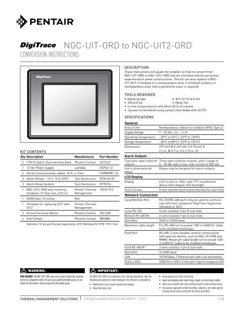
<strong>NGC</strong>-<strong>UIT</strong>-<strong>ORD</strong> <strong>to</strong> <strong>NGC</strong>-<strong>UIT</strong>2-<strong>ORD</strong>Conversion InstructionsDescriptionThese instructions will guide the installer on how <strong>to</strong> convert from<strong>NGC</strong>-<strong>UIT</strong>-<strong>ORD</strong> <strong>to</strong> <strong>NGC</strong>-<strong>UIT</strong>2-<strong>ORD</strong> and are intended only for personnelexperienced in panel constructions. This kit can also replace a <strong>NGC</strong>-<strong>UIT</strong>-OUT if installed in a nonhazardous area. If installed outdoors innonhazardous area, then a protective cover is required.Tools Required• Masking tape• #16 (3/16) drill bit• 3/8 drill bit• Metal file• In-line <strong>to</strong>rque wrench with 8mm (5/16 in) socket• Jig saw (recommend using carbon steel blade with 24TPI)Kit ContentsQty Description Manufacturer Part Number2 9 Pin D-Sub <strong>to</strong> 10 pin terminal block Phoenix Contact 23151621 12 Vdc Power Supply Lambda DSP60-122 Serial Communication cables, 10 ft. L-Com CSMN9MF-103 Alarm Relays – 12 V, 12 A, SPDT Tyco Electronics RTB14012F3 Alarm Relay Sockets Tyco Electronics RT787241 <strong>NGC</strong>-<strong>UIT</strong>2-<strong>ORD</strong> and mountinghardware (12 Kep nuts, 6/32 in)1 DIN35 Rail, 10 inches N/A1 Template for replacing <strong>UIT</strong>1 with<strong>UIT</strong>2<strong>Pentair</strong> ThermalManagement<strong>Pentair</strong> ThermalManagement10332-0133 Ground Terminal Blocks Phoenix Contact 30312384 End Clamps Phoenix Contact 0800886Optional–To be purchased separately–<strong>UIT</strong>2 Window Kit P/N T1011164SpecificationsGeneralArea of Use Nonhazardous, indoors or outdoors (IP65, Type 4)Supply Voltage9 – 30 Vdc, 3.6 – 1.2 AOperating Temperature –30°C <strong>to</strong> 60°C (–22°F <strong>to</strong> 140°F)S<strong>to</strong>rage Temperature –30°C <strong>to</strong> 80°C (–22°F <strong>to</strong> 176°F)Dimensions279 mm W X 229 mm H X 70 mm D(11 in. W X 9 in. H X 2.75 in. D)Alarm OutputsTransis<strong>to</strong>r open collec<strong>to</strong>routputsUse <strong>to</strong> drive externalrelaysLCD DisplayDisplayTouch ScreenNetwork ConnectionLocal/Remote PortLocal RS-232Remote RS-485 #2Data RateMaximum cable lengthField PortField RS-485 #1Data RateLANStatus LEDsThree open collec<strong>to</strong>r outputs, with a range of5 – 30 Vdc with a max. sink current of 500 mARelays may be assigned for alarm outputs.LCD is a 8.4 in. XGA, color TFT transflectivedevice with integral LED backlight5-wire resistive <strong>to</strong>uch screen interface for user entryRS-232/RS-485 ports may be used <strong>to</strong> communicatewith host computers (DigiTrace SupervisorSoftware) or DCSA non-isolated, 9 pin D sub male2-wire isolated, 9 pin D sub male9600 <strong>to</strong> 57600 baud.For RS-485 not <strong>to</strong> exceed 1200 m (4000 ft). Cable<strong>to</strong> be shielded twisted pair.RS-485, 2-wire isolated. Used <strong>to</strong> communicatewith external devices, such as <strong>NGC</strong>-30-CRM andRMM2. Maximum cable length not <strong>to</strong> exceed 1200m (4000 ft). Cable <strong>to</strong> be shielded twisted pair.2-wire isolated, 9 pin D sub maleTo 9600 baud10/100 Base-T Ethernet port with Link and ActivityUSB Ports USB 2.0 Host port Type A receptacle (X2)WARNING:FIRE Hazard: The <strong>NGC</strong>-<strong>UIT</strong>2-<strong>ORD</strong> must not be used in hazardous locations.Electrical components within the unit could ignite flammable gases. Do notinstall the unit where it may be exposed <strong>to</strong> flammable gases.IMPORTANT:The <strong>NGC</strong>-<strong>UIT</strong>2-<strong>ORD</strong> is an electronic unit. During installation, take thefollowing precautions <strong>to</strong> avoid damage <strong>to</strong> its electronic components.• Handle with care <strong>to</strong> avoid mechanical damage.• Keep electronics dry.• Avoid exposure <strong>to</strong> static electricity.• Avoid contamination with metal filings, liquids, or other foreign matter.• Take care <strong>to</strong> protect the user interface board on the enclosure door.• Use agency-approved conduit bushings, adapters, and cable glands<strong>to</strong> keep the enclosure protected from dust and fluids.THERMAL MANAGEMENT SOLUTIONS EN-DigiTrace<strong>NGC</strong><strong>UIT</strong><strong>to</strong><strong>UIT</strong>2-IM-H58770 01/131 / 8
1 Removing the Existing <strong>NGC</strong>-<strong>UIT</strong>-<strong>ORD</strong> 2 Removing the Existing <strong>NGC</strong>-<strong>UIT</strong>-<strong>ORD</strong>Caution – Power <strong>to</strong> the Electrical panel that ishousing the <strong>NGC</strong>-<strong>UIT</strong>-<strong>ORD</strong> must be turned OFFbefore proceeding.1. Loosen and remove all 10 screws and remove the<strong>NGC</strong>-<strong>UIT</strong>-<strong>ORD</strong> from the panel door.1. Disconnect the cables from the <strong>NGC</strong>-<strong>UIT</strong>-<strong>ORD</strong> byloosening the retaining screws that secure the Phoenixconnec<strong>to</strong>rs <strong>to</strong> the mating terminals on the <strong>NGC</strong>-<strong>UIT</strong>-<strong>ORD</strong>. This includes the serial communications (RS-485),Relay outputs and AC Input.<strong>NGC</strong>-<strong>UIT</strong>displayInside ofpanel door3 Removing the Existing <strong>NGC</strong>-<strong>UIT</strong>-<strong>ORD</strong>1. Disconnect the wires from the Phoenix connec<strong>to</strong>rs. Undoall the cable ties for the wiring bundle <strong>to</strong> the <strong>NGC</strong>-<strong>UIT</strong>-<strong>ORD</strong>. These wires will be used for the <strong>NGC</strong>-<strong>UIT</strong>2-<strong>ORD</strong>once it is installed.Cable tiesTHERMAL MANAGEMENT SOLUTIONS EN-DigiTrace<strong>NGC</strong><strong>UIT</strong><strong>to</strong><strong>UIT</strong>2-IM-H58770 01/13 2 / 8
Enlarging the <strong>NGC</strong>-<strong>UIT</strong> openingUse the foldout template as the guide for enlarging the cu<strong>to</strong>ut.Template is actual size (see attached at back of booklet)Instructions1. Line up the upper left hand corner of the template with theexisting cu<strong>to</strong>ut. Use masking tape <strong>to</strong> secure the template<strong>to</strong> the panel door. The dashed lines indicate the areas thatmust be removed.2. Using a center punch, mark the 12 mounting holes, M1–M12.3. Using a center punch, mark the 3 holes used <strong>to</strong> insert a cuttingblade, H1–H3.4. After making the marks using the center punch, remove thetemplate.5. Using a straight edge and marking pen, draw a line startingfrom the upper left hand corner <strong>to</strong> the center of hole H1.Repeat the line from the center of hole H1 <strong>to</strong> H2 and H3.6. Use a 3/16 drill bit and drill all 12 mounting holes, M1–M12.7. Use a 3/8 drill bit and drill the 3 holes used <strong>to</strong> insert thecutting blade, H1–H3.8. Using a jigsaw start the cut from the bot<strong>to</strong>m left corner ofthe existing cu<strong>to</strong>ut and follow the marked line <strong>to</strong> the centerof hole H1. Continue the cut <strong>to</strong> hole H2 and H3. End the cutat the upper right hand corner of the existing cu<strong>to</strong>ut.9. Debur all cut edges before installing the new <strong>UIT</strong>2.Masking tapeInside ofpanel door<strong>UIT</strong> 2 cu<strong>to</strong>ut patternM1M2 M3 M4H3UPPERLEFT HANDCORNERM12Original PanelCu<strong>to</strong>ut AreaM5M11DrawingNot <strong>to</strong> ScaleM6H1<strong>UIT</strong>2 PanelCu<strong>to</strong>utH2M10M9M8M7THERMAL MANAGEMENT SOLUTIONS EN-DigiTrace<strong>NGC</strong><strong>UIT</strong><strong>to</strong><strong>UIT</strong>2-IM-H58770 01/133 / 8
Installing the <strong>NGC</strong>-<strong>UIT</strong>2-<strong>ORD</strong>1. Insert the <strong>NGC</strong>-<strong>UIT</strong>2-<strong>ORD</strong> in<strong>to</strong> the panel door opening.Verify that the gasket that came with the <strong>NGC</strong>-<strong>UIT</strong>2-<strong>ORD</strong>is properly installed. Secure the <strong>UIT</strong>2 using the twelve 8-32nuts and hardware.2. After the display is properly positioned, tighten the nuts <strong>to</strong>0.9 new<strong>to</strong>n-meters (8-inch-pounds) of <strong>to</strong>rque using a 8mm(5/16 in) wrench. Tighten Kep nuts in the sequence shownfor proper sealing.19113587Not <strong>to</strong> Scale6421210Installing the DIN Rail components1. Locate an area in the panel where the componentsmounted on the DIN rail can be installed. If there is DINrail space available then mount these on components onthe available space.10.00 inchBK543WH21BK543WH21121114121114121114LNPhoenix 0800886Phoenix 3031238SH 9 8 7 6Field PortPhoenix 3031238SH 9 8 7 6Remote PortPhoenix 0800886RelaySPDTRTB14012FRelaySPDTRTB14012FRelaySPDTRTB14012FPhoenix 0800886Power SupplyLambda12 Vdc @ 4.5 AmpsDSP60-12Phoenix 3031238Phoenix 0800886SocketRT78724A2A1SocketRT78724A2A1SocketRT78724A2A1–– + +Vout Adj.THERMAL MANAGEMENT SOLUTIONS EN-DigiTrace<strong>NGC</strong><strong>UIT</strong><strong>to</strong><strong>UIT</strong>2-IM-H58770 01/13 4 / 8
Connect Power1. Connect the AC voltage wires that were removed from the<strong>NGC</strong>-<strong>UIT</strong> <strong>to</strong> the AC input on the 12V power supply. Refer<strong>to</strong> wiring diagram below. The illustration below shows thewires from the <strong>UIT</strong>1 (dashed lines) going <strong>to</strong> the power supplyAC input.2. Connect the DC side of the power supply <strong>to</strong> the <strong>UIT</strong>2 DC input,one side of the alarm relays and DC input <strong>to</strong> the alarmrelay driver outputs.Back of <strong>UIT</strong>RS-485 PORTSFAIL SAFE RELAY OUTPUTSAC INPUTFIELD REMOTESIG–SIG+SHLDSIG–SIG+SHLD1 2 3 4 5 6WH BK S SWH BKRELAY 1 RELAY 2 RELAY 31 2 3 4 5 6 7 8 9 10 11Line/L1N/L21 2 3N\L2Line\L1AC InputBKWHBKWH1212125432 15432 1111411141114LNPhoenix 0800886Phoenix 3031238SH 9 8 7 6Field PortPhoenix 3031238SH 9 8 7 6Remote PortPhoenix 0800886RelaySPDTRTB14012FRelaySPDTRTB14012FRelaySPDTRTB14012FPhoenix 0800886Power SupplyLambda12 Vdc @ 4.5 AmpsDSP60-12Phoenix 3031238Phoenix 0800886SocketA2RT78724A1SocketA2RT78724A1SocketA2RT78724A1–– + +Vout Adj.+8 7 6 5 4 3 2 1–Door MountedTHERMAL MANAGEMENT SOLUTIONS EN-DigiTrace<strong>NGC</strong><strong>UIT</strong><strong>to</strong><strong>UIT</strong>2-IM-H58770 01/135 / 8
Connecting the Alarm Relays1. The illustration below shows the wiring for the alarmrelays from <strong>UIT</strong>1 (dashed lines) <strong>to</strong> <strong>UIT</strong>2. TB-X’s are the fieldterminals. Refer <strong>to</strong> the panel wiring for location of the fieldterminals.2. Connect the Relay Driver Output signals <strong>to</strong> the relays shownin the illustration below.RS-485 PORTSBackside of <strong>UIT</strong>FAIL SAFE RELAY OUTPUTSAC INPUTFIELD REMOTESIG–SIG+SHLDSIG–SIG+SHLD1 2 3 4 5 6WH BK S SWH BKRELAY 1 RELAY 2 RELAY 31 2 3 4 5 6 7 8 9 10 11Line\L1N\L21 2 3TB-XTB-XTB-XTB-XTB-XTB-X14 13ARFuseNeutralLineTo Alarm Lamp/SwitchMounted on Panel DoorBK54WH3 2 1BK54WH3 2 1111214111214111214LNPhoenix 0800886Phoenix 3031238SH 9 8 7 6Field PortPhoenix 3031238SH 9 8 7 6Remote PortPhoenix 0800886RelaySPDTRTB14012FSocketA2RT78724A1RelaySPDTRTB14012FSocketA2RT78724A1RelaySPDTRTB14012FSocketA2RT78724A1Phoenix 0800886Power SupplyLambda12 Vdc @ 4.5 AmpsDSP60-12–– + +Phoenix 3031238Phoenix 0800886Vout Adj.+8 7 6 5 4 3 2 1–Door MountedTHERMAL MANAGEMENT SOLUTIONS EN-DigiTrace<strong>NGC</strong><strong>UIT</strong><strong>to</strong><strong>UIT</strong>2-IM-H58770 01/13 6 / 8
Communications1. The illustration below shows the wiring for RS-485 portsfrom <strong>UIT</strong>1 (dashed lines) <strong>to</strong> <strong>UIT</strong>2. Refer <strong>to</strong> the panel wiringfor location of the field terminals.2. Connect the RS-485 serial cables <strong>to</strong> the appropriate commport on the <strong>UIT</strong>2 as shown in the illustration.Backside of <strong>UIT</strong>RS-485 PORTSFAIL SAFE RELAY OUTPUTSAC INPUTFIELD REMOTESIG–SIG+SHLDSIG–SIG+SHLD1 2 3 4 5 6WH BK S WH BK SRELAY 1 RELAY 2 RELAY 31 2 3 4 5 6 7 8 9 10 11Line\L1N\L21 2 3RS-485RS-485CRM(S)WH BK S3 2 13 2 1WH BK SWH BK S3 2 1Continue <strong>to</strong>other CRM(s)BK54WH3 2 1BK54WH3 2 1121114121114121114LNPhoenix 0800886Phoenix 3031238SH 9 8 7 6Field PortPhoenix 3031238SH 9 8 7 6Remote PortPhoenix 0800886RelaySPDTRTB14012FRelaySPDTRTB14012FRelaySPDTRTB14012FPhoenix 0800886Power SupplyLambda12 Vdc @ 4.5 AmpsDSP60-12Phoenix 3031238Phoenix 0800886SocketA2RT78724A1SocketA2RT78724A1SocketA2RT78724A1–– + +Vout Adj.Serial CablesDoor MountedTHERMAL MANAGEMENT SOLUTIONS EN-DigiTrace<strong>NGC</strong><strong>UIT</strong><strong>to</strong><strong>UIT</strong>2-IM-H58770 01/137 / 8
<strong>NGC</strong>-<strong>UIT</strong>2-HAZ Cut Out Dimensions10.82 mm(0.426 in)88.39 mm(3.480 in)Panel Cut Out243.54 mm(9.588 in)88.39 mm(3.480 in)88.39 mm(3.480 in)71.48 mm(2.814 in)11.1 mm(0.437 in)Ø 4.83 mm (0.190 in) X12Top of DisplayPanel Cut Out190.7 mm(7.508 in)71.48 mm(2.814 in)Panel Cut Out Area71.48 mm(2.814 in)DrawingNOT TO SCALEWWW.THERMAL.PENTAIR.COMNORTH AMERICATel: +1.800.545.6258Fax: +1.800.527.5703Tel: +1.650.216.1526Fax: +1.650.474.7711thermal.info@pentair.comEurope, Middle East, AfricaTel: +32.16.213.511Fax: +32.16.213.603thermal.info@pentair.comAsia PacificTel: +86.21.2412.1688Fax: +86.21.5426.2917cn.thermal.info@pentair.comLatin AmericaTel: +55.11.2588.1400Fax: +55.11.2588.1410thermal.info@pentair.com<strong>Pentair</strong>, <strong>NGC</strong> and DigiTrace are owned by <strong>Pentair</strong> or its global affiliates. All other trademarks are the property of their respective owners. <strong>Pentair</strong> reservesthe right <strong>to</strong> change specifications without prior notice.© 2011-2013 <strong>Pentair</strong>.THERMAL MANAGEMENT SOLUTIONS EN-DigiTrace<strong>NGC</strong><strong>UIT</strong><strong>to</strong><strong>UIT</strong>2-IM-H58770 01/138 / 8