Open Stub J-Poles - Cascade Amateur Radio Society
Open Stub J-Poles - Cascade Amateur Radio Society
Open Stub J-Poles - Cascade Amateur Radio Society

You also want an ePaper? Increase the reach of your titles
YUMPU automatically turns print PDFs into web optimized ePapers that Google loves.
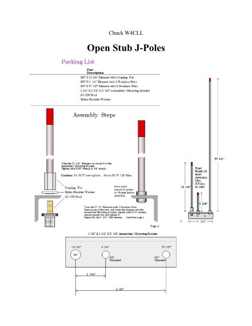
Chuck W4CLL<strong>Open</strong> <strong>Stub</strong> J-<strong>Poles</strong>
Build a 2 Meter, 5/4 Wave AntennaBy Mike Martell N1HFXMany RASON members truly enjoyed last month's collinear antenna. This month I decided to build a 2meter 5/4 wave antenna. This antenna is unique in that it is enclosed entirely in 3/4" PVC which makesthe design a little more complicated. The primary problem is that PVC tubing has a significant velocityfactor which causes RF to slow down. This means that an antenna encased in PVC will normally need tohave it's physical length reduced by about 19%. To further complicate the design, a 5/4 wave antenna'simpedance has a highly inductive component which must be tuned out to get a good match. Fortunately,the design in Figure 1 solves all of these problems.This antenna is made with the following components:About 2 feet of outdoor type 300 ohm TV twin lead (Used for matching system.)About 5 feet of #18 stranded insulated wire (Used for radiating element.)About 5 feet of RG58/U coaxOne PL259 ConnectorOne PL259 female to female couplerAbout 8 feet of 3/4" PVC tubing. (normally sold in 10 foot lengths)Two 3/4" PVC end capsAbout 8 feet of 1/4" hardwood dowel (normally sold in 4 or 5 foot lengths)About 25 small tie wrapsMiscellaneous PVC cement, solder, small piece of tubing, etc.The twin lead was originally cut for 20 inches with 4 7/8 inches cut back on the braid or ground side. The #18 insulated wire was cut toexactly 57 3/4 inches. The overall length of the antenna assembly is 77 3/4 inches. This indicates a velocity factor of about .81 compared to anormal 5/4 wave 146 Mhz antenna. See calculation below:234 * 5 / 146 X .81 = 6.49 feet or about 77.88 inchesNow that we have all our parts, lets begin assembly by cutting back the insulation of the coax and the TVtwin lead. We will need to cut back the coax to expose the center conductor as well as part of the braid. Itis a good idea to lightly thin the braid with solder to prevent any strands from shorting out to the centerconductor. Solder the center conductor to one end of the twin lead and solder the braid to the other endoff the twin lead as in Figure 1. Notice the braid of the coax is soldered to the shorter part of the twin leadwhich is left open. This serves as our matching system which adds capacitance to our antenna to offsetthe inductive component of the antenna. Trim the twin lead to 20 inches and solder about 60 inches of#18 stranded wire to the twin lead as in Figure 1. The insulation should not be removed except asnecessary for soldering.Prepare the 1/4" hardwood dowel by joining two 4 or 5 foot lengths together. The ends can be joined bycrimping a 1 inch length of 5/16" aluminum tubing or using a good quality wood glue. Now attach thecoax, twin lead and wire assembly to the 1/4" dowel using tie wraps about every 3 inches. Pull the twinlead and wire to keep it as straight as possible. Before attaching the PL259 connector to the coax, drill a
hole in one of the PVC end caps and slide it over the coax to prepare for permanent mounting in the PVC.Now attach the PL259 connector as well as any other connectors needed to check SWR. Cut back theopen end of the twin lead to about 16 inches as in Figure 1.Now we are ready for final tuning. Slide the antenna, dowel assembly inside the 3/4" PVC first. All SWRreadings must be taken with the antenna, dowel assembly inside the PVC tubing or the antenna willappear electrically shorter than necessary. Check SWR on both the top and bottom edge of the band. Ifthe SWR is higher at 147.995 Mhz than at 144.005 Mhz then the antenna is too long and should beshortened. Cut off no more than a 1/4" at a time of the #18 wire. Also, trim the open end of the twin leadby no more than 1/8" at a time to further lower SWR. Remember the twin lead is simply a matchingsystem which changes impedance and has no real effect on the electrical lengh of the antenna. The finallenghs of the #18 wire and twin lead should very closely resemble those listed in Figure 1. The prototypeantenna achieved SWR readings of less then 1.2 to 1 across the entire 2 meter band. Remember to keepthe antenna away from metal objects when checking SWR.After the antenna is properly tuned, trim the antenna dowel assembly to about 7 feet. Leave a few inchesof coax attached to the bottom of the dowel so that the mast will be away from the twin lead portion of theantenna when mounted. Trim the PVC tubing to about 7' 2" and cement the top end cap. Double checkSWR before cementing the bottom end cap. After SWR has been doubled checked, slide the antenna,dowel assembly into the PVC and cement the bottom end cap. If desired, styrofoam spacers may be usedto get a very snug fit. Waterproof the bottom end cap where the coax leaves the antenna. Whencompleted, the antenna should resemble Figure 2.When mounting the antenna, use a PL259 female to female coupler. Do not use RG58/U for the entirefeed line because it is too lossy. Use good quality RG8/U or similar coax for the feedline. Of course, donot forget to waterproof the female to female coupler. Mount to any mast using standard TV antennaclamps at the bottom of the antenna and keep it high and away from other metal objects for bestperformance and lowest SWR.Although not actually measured, this antenna should give at least 6 dB gain if mounted high enough.Remember, the small diameter of the radiating element has no effect on the radiation resistance. Theonly real benefit with using a large diameter radiating element is durability and slightly improvedbandwidth. This antenna should give many years of reliable performance for a fraction of the cost of acommercial antenna.DE N1HFX
Quarter-wave vertical antennas are useful for local communications when size, cost and ease ofconstruction are important.The antennas shown are built on a coaxial connector. Use UHF or N connectors for the fixed stationantennas. BNC connectors are good for mobile and portable antennas. BNCand N connectors are better than PL-259 connectors for VHF/UHF outdoor use because: (1) they providea constant impedance over the frequencies of interest, and(2) they are weatherproof when the appropriate connector or cap is attached. The ground-plane antennasrequire a panel-mount connector (it has mounting holes to hold the radials).If the antenna is sheltered from weather, copper wire is sufficiently rigid for the element and radials.Antennas exposed to the weather should be made from 1/16- to 1/8-inch brass or stainless-steel rod.Radials may be made from 3/16-inch aluminum rod or tubing and mounted on an aluminum sheet. Do notuse aluminum for the antenna element because it cannot be easily soldered to the coaxial-connectorcenter pin. Where the figures call for #4-40 hardware, stainless steel or brass is best. Use cadmiumplated hardware if stainless steel or brass is not available.
To: All <strong>Amateur</strong>sFrom: Gary - KG0ZPRE: The COPPER CACTUS ANTENNADear Fellow HamsHere are the numbers for the Copper Cactus J-Pole antenna!I hope you are already familiar with the construction of the standard J-Pole antenna, so I won't go into anyunnecessary detail.The antenna may be built as a MonoBander, DuoBander, TriBander, QuadBander or whatever with greatsuccess.You can either feed it with separate coax's for each band or a single coax, however, separate coax's make itmuch easier to tune.Theres no trick to building them, just remember the overall length is for the lowest frequency of operation. Inother words, a MonoBander, DualBander and TriBander are all exactly the same length overall 58.09" on2mtrs.Feed the coax up the center of the pipes. Use T-Fittings at the proper distance below the top of the antenna forthe desired frequency. The only problem is that the more bands you try to incorporate into the antenna, theharder it is to get the SWR flat on all bands.Here are the numbers you are looking for:Frequency 52MHz 146MHz 223.5MHz 435MHz 912MHz 1265MHZPipe Dia. 1" 3/4" 1/2" 1/2" 3/8" 3/8"<strong>Stub</strong> 54.70" 19.36" 12.65" 6.46" 3.02" 2.16"Overall Length 163.92" 58.09" 37.94" 19.39" 9.07" 6.49"Separation 5" 2" 1-1/4" 3/4" 1/2" 1/4"Connect at 6" 2-1/4" 1-1/2" 1" 3/4" 1/2"For best results, build the highest band first, for eg. the 435MHz antenna, If you really want it to look neat, use3/8" copper for the vertical and 1/4" copper for the transformer section (stub). Naturally the finished product willbe in the shape of a "J".Now build the next band, for eg. the 223.5MHz antenna, by adding pipe to the T-connector that is the base(mast mount) of the 435MHz antenna, I use 1/2" for the vertical and 3/8" for the stub of this section.Now build the 146MHz antenna, don't forget the overall length of the antenna is the lowest frequency you willbe using. I use 3/4" for the vertical and 1/2 for the stub.The stub must be parallel to the vertical, however you can point the base of each stub in any direction you like.I prefer 3 equal distant points, but you can make them all on the same side if you wish. I feel the three pointsmake it look like a cactus.My measurements on overall length, and stub length are from the centerline of the separation pipe (horizontal)to the top of the antenna. The Separation distance is technically from centerline to centerline, but insidemeasurements are fine and visually look better.Some of the measurements are less than physically possible, in this case just push the T-Fitting and elbow asclose together as you can get them, no need to trim the fittings.
The Connect at measurement is from the top of the horizontal member to the point of connection.Final Note: If you use 1/2" pipe for all the construction, on the 2-meter stub, add 1/4" to its length, or use pipecapsand adjust them up or down to get the 1/4" additional length.The antenna should be in perfect tune, SWR less than 1.2 - 1 on all bands, using separate coax for each band.Solder all the joints before installing the coax, any pipe you have left over can be used as the mast.To install the coax, drill a 1/4" hole in the top of the horizontal part of each T-fitting closest to the vertical, thentilt the drill at an angle, so that the drill bit is sorta heading down the vertical.Enjoy Building: If you have any questions just ask, or further instructions, just send me a message and I willpromptly respond.PS Until you are familiar with the construction techniques of the J-Pole, I wouldn't attempt any more than threebands the first time out. In fact, A dual-bander, using the above dimensions will be perfect every time.73s de Gary - KGØZPDocument Revision Date 2/26/98 Applicable To This Page Only••Copper Cactus antenna••