Advances in the Modelling of Motorcycle Dynamics - ResearchGate
Advances in the Modelling of Motorcycle Dynamics - ResearchGate
Advances in the Modelling of Motorcycle Dynamics - ResearchGate
You also want an ePaper? Increase the reach of your titles
YUMPU automatically turns print PDFs into web optimized ePapers that Google loves.
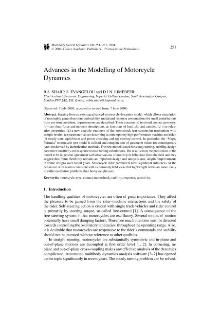
Multibody System <strong>Dynamics</strong> 12: 251–283, 2004.C○ 2004 Kluwer Academic Publishers. Pr<strong>in</strong>ted <strong>in</strong> <strong>the</strong> Ne<strong>the</strong>rlands.251<strong>Advances</strong> <strong>in</strong> <strong>the</strong> Modell<strong>in</strong>g <strong>of</strong> <strong>Motorcycle</strong><strong>Dynamics</strong>R.S. SHARP, S. EVANGELOU and D.J.N. LIMEBEERElectrical and Electronic Eng<strong>in</strong>eer<strong>in</strong>g, Imperial College London, South Kens<strong>in</strong>gton Campus,London SW7 2AZ, UK; E-mail: rob<strong>in</strong>.sharp@imperial.ac.uk(Received: 7 July 2003; accepted <strong>in</strong> revised form: 7 June 2004)Abstract. Start<strong>in</strong>g from an exist<strong>in</strong>g advanced motorcycle dynamics model, which allows simulation<strong>of</strong> reasonably general motions and stability, modal and response computations for small perturbationsfrom any trim condition, improvements are described. These concern (a) tyre/road contact geometry,(b) tyre shear force and moment descriptions, as functions <strong>of</strong> load, slip and camber, (c) tyre relaxationproperties, (d) a new analytic treatment <strong>of</strong> <strong>the</strong> monoshock rear suspension mechanism withsample results, (e) parameter values describ<strong>in</strong>g a contemporary high performance mach<strong>in</strong>e and rider,(f) steady-state equilibrium and power check<strong>in</strong>g and (g) steer<strong>in</strong>g control. In particular, <strong>the</strong> “MagicFormula” motorcycle tyre model is utilised and complete sets <strong>of</strong> parameter values for contemporarytyres are derived by identification methods. The new model is used for steady turn<strong>in</strong>g, stability, designparameter sensitivity and response to road forc<strong>in</strong>g calculations. The results show <strong>the</strong> predictions <strong>of</strong> <strong>the</strong>model to be <strong>in</strong> general agreement with observations <strong>of</strong> motorcycle behaviour from <strong>the</strong> field and <strong>the</strong>ysuggest that frame flexibility rema<strong>in</strong>s an important design and analysis area, despite improvements<strong>in</strong> frame designs over recent years. <strong>Motorcycle</strong> rider parameters have significant <strong>in</strong>fluences on <strong>the</strong>behaviour, with results consistent with a commonly held view, that lightweight riders are more likelyto suffer oscillation problems than heavyweight ones.Keywords: motorcycle, tyre, contact, monoshock, stability, response, sensitivity.1. IntroductionThe handl<strong>in</strong>g qualities <strong>of</strong> motorcycles are <strong>of</strong>ten <strong>of</strong> great importance. They affect<strong>the</strong> pleasure to be ga<strong>in</strong>ed from <strong>the</strong> rider–mach<strong>in</strong>e <strong>in</strong>teractions and <strong>the</strong> safety <strong>of</strong><strong>the</strong> rider. Self-steer<strong>in</strong>g action is crucial with s<strong>in</strong>gle track vehicles and rider controlis primarily by steer<strong>in</strong>g torque, so-called free-control [1]. A consequence <strong>of</strong> <strong>the</strong>free steer<strong>in</strong>g system is that motorcycles are oscillatory. Several modes <strong>of</strong> motionpotentially have small damp<strong>in</strong>g factors. Therefore much attention must be directedtowards controll<strong>in</strong>g <strong>the</strong> oscillatory tendencies, throughout <strong>the</strong> operat<strong>in</strong>g range. Also,it is desirable that motorcycles are responsive to <strong>the</strong> rider’s commands and stabilityshould not be pursued without reference to o<strong>the</strong>r qualities.In straight runn<strong>in</strong>g, motorcycles are substantially symmetric and <strong>in</strong>-plane andout-<strong>of</strong>-plane motions are decoupled at first order level [1, 2]. In corner<strong>in</strong>g, <strong>in</strong>planeand out-<strong>of</strong>-plane cross-coupl<strong>in</strong>g makes any effective analysis <strong>of</strong> <strong>the</strong> dynamicscomplicated. Automated multibody dynamics analysis s<strong>of</strong>tware [3–7] has openedup <strong>the</strong> topic significantly <strong>in</strong> recent years. The steady turn<strong>in</strong>g problem can be solved,
252 R.S. SHARP ET AL.possibly with <strong>the</strong> aid <strong>of</strong> a stabilis<strong>in</strong>g steer<strong>in</strong>g controller, and modal analysis can becompleted for small perturbations from any equilibrium “trim” state.Accuracy <strong>of</strong> predicted behaviour depends, not only on effective conceptual modell<strong>in</strong>gand multibody analysis, but also on good parameter values. Central issues<strong>in</strong> modell<strong>in</strong>g <strong>in</strong>clude <strong>the</strong> representations <strong>of</strong> frame flexibilities, tyre–road contactgeometry and tyre shear forces. Many previous f<strong>in</strong>d<strong>in</strong>gs relate to motorcycle andtyre descriptions which are now somewhat dated and to tyre models which havea limited doma<strong>in</strong> <strong>of</strong> applicability. It is <strong>the</strong>refore <strong>of</strong> <strong>in</strong>terest (i) to obta<strong>in</strong> a parametricdescription <strong>of</strong> a modern mach<strong>in</strong>e, (ii) to utilise a more comprehensive tyreforce model, with parameter values to correspond to a modern set <strong>of</strong> tyres, (iii)to determ<strong>in</strong>e steady turn<strong>in</strong>g, stability, response and parameter sensitivity data forcomparison with older <strong>in</strong>formation, to determ<strong>in</strong>e to what extent it rema<strong>in</strong>s valid,and (iv) to better understand <strong>the</strong> design <strong>of</strong> modern mach<strong>in</strong>es. The paper is subsequentlyan account <strong>of</strong> such work. Novel analysis <strong>of</strong> a “monoshock” rear suspensionsystem is also <strong>in</strong>cluded.2. Parametric Description <strong>of</strong> a Modern <strong>Motorcycle</strong>The authors are currently engaged <strong>in</strong> a measurement campaign to obta<strong>in</strong> <strong>the</strong> relevantparameters <strong>of</strong> a Suzuki GSX-R1000K1 mach<strong>in</strong>e. Such a motorcycle has beendisassembled and many <strong>of</strong> its parts have been measured, start<strong>in</strong>g with <strong>the</strong> lighterones. At this stage, <strong>the</strong> campaign is <strong>in</strong>complete. In particular, <strong>the</strong> frame stiffnessand damp<strong>in</strong>g parameters used and <strong>the</strong> location <strong>of</strong> <strong>the</strong> elastic centre are currentlyonly estimates.2.1. GEOMETRY AND MASSESThe workshop manual for <strong>the</strong> motorcycle <strong>in</strong>cludes pictures to scale and key dimensions,like <strong>the</strong> wheelbase and <strong>the</strong> steer<strong>in</strong>g head angle. Jo<strong>in</strong>ts between componentsat <strong>the</strong> steer<strong>in</strong>g head and <strong>the</strong> sw<strong>in</strong>g arm pivot can be identified <strong>the</strong>re and many keypo<strong>in</strong>ts, <strong>in</strong>clud<strong>in</strong>g those related to <strong>the</strong> monoshock rear suspension, can be locatedwith reasonable precision from <strong>the</strong>se pictures. A scaled diagrammatic representation<strong>of</strong> <strong>the</strong> motorcycle is shown <strong>in</strong> Figure 1, <strong>the</strong> correspond<strong>in</strong>g parameter valuesbe<strong>in</strong>g <strong>in</strong>cluded <strong>in</strong> an Appendix. The front frame has been measured separately togive <strong>the</strong> po<strong>in</strong>ts p3 and p5. The po<strong>in</strong>t p4 is along <strong>the</strong> l<strong>in</strong>e <strong>of</strong> <strong>the</strong> lower front forktranslation relative to <strong>the</strong> upper forks. The estimated location p2 is <strong>the</strong> elastic centre<strong>of</strong> <strong>the</strong> rear frame with respect to a moment perpendicular to <strong>the</strong> steer axis.The rider’s total mass is taken as 72 kg, 62% <strong>of</strong> which is associated with <strong>the</strong>upper body. The masses <strong>of</strong> <strong>the</strong> hands and half <strong>of</strong> <strong>the</strong> lower arms may be consideredto be part <strong>of</strong> <strong>the</strong> steer<strong>in</strong>g system. The rider parameters derive from bio-mechanicaldata [8], account<strong>in</strong>g for his posture on <strong>the</strong> mach<strong>in</strong>e.Circles represent<strong>in</strong>g <strong>the</strong> body mass centres are <strong>in</strong> proportion to <strong>the</strong> massesconcerned, which are known through straightforward weigh<strong>in</strong>g.
ADVANCES IN THE MODELLING OF MOTORCYCLE DYNAMICS 253Figure 1. Scaled diagrammatic motorcycle <strong>in</strong> side view.2.2. INERTIAS AND MASS CENTRESWheel and tyre <strong>in</strong>ertias have been obta<strong>in</strong>ed by tim<strong>in</strong>g oscillations <strong>of</strong> bi-filar andtri-filar suspension arrangements, utilis<strong>in</strong>g axial symmetry <strong>in</strong> each set-up. Similarbi-filar suspension systems have been used separately for <strong>the</strong> front and rear frames(Figure 2). Each <strong>of</strong> <strong>the</strong>se is assumed to have a plane <strong>of</strong> symmetry and it is clear that<strong>the</strong> front frame pr<strong>in</strong>cipal axes, <strong>in</strong> <strong>the</strong> plane <strong>of</strong> symmetry, are along and perpendicularto <strong>the</strong> l<strong>in</strong>e <strong>of</strong> <strong>the</strong> forks. Oscillation periods, geometric dimensions and <strong>the</strong> mass <strong>of</strong><strong>the</strong> suspended body lead simply to <strong>the</strong> moment <strong>of</strong> <strong>in</strong>ertia about <strong>the</strong> rotation axisand standard transformations allow <strong>the</strong> determ<strong>in</strong>ation <strong>of</strong> pr<strong>in</strong>cipal <strong>in</strong>ertias and axesfor <strong>the</strong> more complex rear frame [9].Recent measurements on a driv<strong>in</strong>g simulator [10] provide estimates <strong>of</strong> <strong>the</strong>contributions to <strong>the</strong> front frame <strong>in</strong>ertia, steer<strong>in</strong>g stiffness and steer<strong>in</strong>g damp<strong>in</strong>gthat arise from <strong>the</strong> rider’s arms and hands, correspond<strong>in</strong>g to relaxed and tenserid<strong>in</strong>g. These can be added to <strong>the</strong> measured values if it is considered appropriate[11]. The sw<strong>in</strong>g arm <strong>in</strong>ertias are small enough to be obta<strong>in</strong>ed by estimationbased on <strong>the</strong> mass centre location and <strong>the</strong> dimensions. The wheels have <strong>the</strong>ir masscentres at <strong>the</strong>ir geometric centres. O<strong>the</strong>r mass centre locations were found us<strong>in</strong>gplumb l<strong>in</strong>es and tak<strong>in</strong>g photographs (Figure 2). Relevant values are given <strong>in</strong> <strong>the</strong>appendix.2.3. STIFFNESS AND DAMPING PROPERTIESSpr<strong>in</strong>gs and dampers were tested <strong>in</strong> a standard dynamic materials test<strong>in</strong>g mach<strong>in</strong>e[12]. The maximum actuator velocity available was about 0.25 m/s, which constra<strong>in</strong>ed<strong>the</strong> damper characteristic measurements. Uni-directional forc<strong>in</strong>g <strong>of</strong> <strong>the</strong>steer<strong>in</strong>g damper up to <strong>the</strong> maximum rate <strong>of</strong> <strong>the</strong> actuator yielded a substantiallyl<strong>in</strong>ear force/velocity relationship with slope 4340 N/(m/s). Us<strong>in</strong>g <strong>the</strong> effective
254 R.S. SHARP ET AL.Figure 2. Bifilar suspended motorcycle rear frame for <strong>in</strong>ertia measurement.moment arm <strong>of</strong> <strong>the</strong> damper (0.04 m) to convert this value to an equivalent rotationalcoefficient gives a value, 6.944 Nm/(rad/s).The dimensions <strong>of</strong> <strong>the</strong> s<strong>in</strong>gle rear steel spr<strong>in</strong>g, from <strong>the</strong> monoshock suspensionwere measured and <strong>the</strong> standard helical spr<strong>in</strong>g formula, k = Gd 4 /(64R 3 n), wasapplied to calculat<strong>in</strong>g <strong>the</strong> rate, k, as55kN/m. The gas filled damper contributessome suspension preload and a small rate, determ<strong>in</strong>ed from <strong>the</strong> test mach<strong>in</strong>e viastatic measurements as 3.57 kN/m. The damper unit was stroked at full actuator
ADVANCES IN THE MODELLING OF MOTORCYCLE DYNAMICS 255performance first <strong>in</strong> compression and <strong>the</strong>n <strong>in</strong> extension, achiev<strong>in</strong>g velocities up toabout 0.13 m/s. Allow<strong>in</strong>g for <strong>the</strong> gas pressure forces <strong>in</strong> <strong>the</strong> process<strong>in</strong>g, <strong>the</strong> damp<strong>in</strong>gcoefficient <strong>in</strong> compression was 9.6 kN/(m/s) and <strong>in</strong> rebound 13.7 kN/(m/s). Frontspr<strong>in</strong>g and damper coefficients are estimates, at this stage. Suspension limit stops are<strong>in</strong>cluded at each end, modelled as fifth powers <strong>of</strong> displacement from stop contact.The relevant displacements are known from exam<strong>in</strong>ation <strong>of</strong> <strong>the</strong> parts and from<strong>in</strong>formation given <strong>in</strong> <strong>the</strong> workshop manual.The torsional stiffness <strong>of</strong> <strong>the</strong> ma<strong>in</strong> frame, between <strong>the</strong> steer<strong>in</strong>g head and <strong>the</strong>power unit, rema<strong>in</strong>s to be measured. It is clear from <strong>the</strong> structural design andmaterials used that <strong>the</strong> frame is considerably stiffer than was <strong>the</strong> norm for tubularframed motorcycles <strong>of</strong> some years ago. In those cases, it was established that <strong>the</strong>frame flexibility was an essential contributor to <strong>the</strong> stability <strong>of</strong> <strong>the</strong> wobble mode,<strong>in</strong> particular [13, 14]. It rema<strong>in</strong>s to be seen how significant this area is for modernmach<strong>in</strong>es. The torsional stiffness assumed, at 10 5 Nm/rad, is 3.5 times that measuredstatically for a Yamaha 650S [15] and 2.9 times that measured at about <strong>the</strong> sametime by Koenen [2]. Tyre radial stiffnesses come directly from [7].The rider’s upper body has roll freedom relative to <strong>the</strong> ma<strong>in</strong> frame, while <strong>the</strong>lower body is part <strong>of</strong> <strong>the</strong> ma<strong>in</strong> frame. The upper body is restra<strong>in</strong>ed by a parallelspr<strong>in</strong>g damper system. Stiffness and damp<strong>in</strong>g parameters are chosen <strong>in</strong> alignmentwith <strong>the</strong> experimental results <strong>of</strong> Nishimi et al [16], obta<strong>in</strong>ed by identify<strong>in</strong>g “rider”parameters <strong>in</strong> forced vibration on a mock motorcycle frame. The decoupled naturalfrequency <strong>of</strong> <strong>the</strong> rider upper body <strong>in</strong> roll is 1.27 Hz and <strong>the</strong> correspond<strong>in</strong>g damp<strong>in</strong>gfactor is 0.489. Accord<strong>in</strong>g to this model, rider resonance will not be apparent due to<strong>the</strong> high damp<strong>in</strong>g factor and it will not be tuned to <strong>the</strong> mach<strong>in</strong>e oscillations, where<strong>the</strong>se are at all vigorous.2.4. AERODYNAMICSAerodynamic drag, lift and pitch<strong>in</strong>g moment data come from a Triumph motorcycle<strong>of</strong> similar style and dimensions to <strong>the</strong> GSX-R1000 [1]. This is steady-state dragforce, lift force and pitch<strong>in</strong>g moment data from full scale w<strong>in</strong>d tunnel test<strong>in</strong>g, witha prone rider.3. Tyre–Road Contact Modell<strong>in</strong>gThe geometry <strong>of</strong> <strong>the</strong> contact between <strong>the</strong> front tyre and <strong>the</strong> ground is a relativelycomplex part <strong>of</strong> <strong>the</strong> motorcycle modell<strong>in</strong>g. It is also important to <strong>the</strong> behaviour <strong>of</strong><strong>the</strong> mach<strong>in</strong>e. It has been common to represent <strong>the</strong> tyre as a th<strong>in</strong> disc, with <strong>the</strong> contactpo<strong>in</strong>t migrat<strong>in</strong>g circumferentially for larger camber and steer angles, but Cossalteret al have pioneered <strong>the</strong> <strong>in</strong>clusion <strong>of</strong> tyre width <strong>in</strong> <strong>the</strong>ir descriptions [7, 17–19].If a disc model is used, it needs to be augmented with an overturn<strong>in</strong>g momentdescription [2, 5]. This is not necessary with a thick tyre model, s<strong>in</strong>ce <strong>the</strong> lateralmigration <strong>of</strong> <strong>the</strong> contact po<strong>in</strong>t <strong>the</strong>n occurs automatically and <strong>the</strong> overturn<strong>in</strong>g momentis a consequence <strong>of</strong> that movement. A wide tyre with a circular cross-section
256 R.S. SHARP ET AL.Figure 3. Diagrammatic three-dimensional front wheel contact geometry.crown is now modelled. In addition to mak<strong>in</strong>g <strong>the</strong> overturn<strong>in</strong>g moment automatic,longitud<strong>in</strong>al forces applied to <strong>the</strong> cambered tyre will lead to realistic align<strong>in</strong>gmoments appear<strong>in</strong>g automatically. A necessary test for <strong>the</strong> wide tyre model isthat it gives <strong>the</strong> same results as <strong>the</strong> th<strong>in</strong> tyre model, when physically equivalentsystems are be<strong>in</strong>g represented. This test has been applied, with some significantconsequences.To def<strong>in</strong>e each tyre/ground contact po<strong>in</strong>t (Figures 3 and 4) <strong>the</strong> vertical and <strong>the</strong>wheel sp<strong>in</strong>dle directions are used <strong>in</strong> a vector (cross) product to describe <strong>the</strong> longitud<strong>in</strong>aldirection, with respect to <strong>the</strong> wheel. Similarly, <strong>the</strong> wheel radial direction, OC<strong>in</strong> Figure 3, comes from comb<strong>in</strong><strong>in</strong>g <strong>the</strong> longitud<strong>in</strong>al and wheel sp<strong>in</strong>dle directions.The vector OC is <strong>of</strong> fixed length and so is completely specified. G is vertically belowC and <strong>the</strong> difference between <strong>the</strong> tyre crown radius and <strong>the</strong> distance CG def<strong>in</strong>es<strong>the</strong> change <strong>in</strong> <strong>the</strong> tyre carcass compression from <strong>the</strong> nom<strong>in</strong>al state and hence <strong>the</strong>change <strong>of</strong> <strong>the</strong> wheel load from <strong>the</strong> nom<strong>in</strong>al, via <strong>the</strong> tyre radial stiffness. If <strong>the</strong> roadis pr<strong>of</strong>iled, <strong>the</strong> road height is accounted for <strong>in</strong> work<strong>in</strong>g out <strong>the</strong> wheel load. Thevector OG = OC + CG def<strong>in</strong>es <strong>the</strong> contact po<strong>in</strong>t, which belongs to <strong>the</strong> wheel butmoves with<strong>in</strong> it. G rema<strong>in</strong>s at road surface height but <strong>the</strong> tyre load cannot becomenegative. If <strong>the</strong> tyre leaves <strong>the</strong> ground, <strong>the</strong> shear forces are zero, whatever <strong>the</strong> o<strong>the</strong>rconditions are. Tyre forces are applied to <strong>the</strong> po<strong>in</strong>t G, <strong>in</strong> each case.The longitud<strong>in</strong>al slip is <strong>the</strong> rearward component <strong>of</strong> <strong>the</strong> material contact po<strong>in</strong>tvelocity divided by <strong>the</strong> absolute value <strong>of</strong> <strong>the</strong> roll<strong>in</strong>g velocity, <strong>the</strong> latter be<strong>in</strong>g <strong>the</strong>forward velocity <strong>of</strong> <strong>the</strong> contact po<strong>in</strong>t (or <strong>the</strong> crown centre po<strong>in</strong>t, s<strong>in</strong>ce <strong>the</strong>se are<strong>the</strong> same). The contact po<strong>in</strong>t is def<strong>in</strong>ed by its coord<strong>in</strong>ates <strong>in</strong> <strong>the</strong> parent body <strong>of</strong> <strong>the</strong>wheel and it is de-spun relative to <strong>the</strong> material contact po<strong>in</strong>t. Thus <strong>the</strong> longitud<strong>in</strong>al
ADVANCES IN THE MODELLING OF MOTORCYCLE DYNAMICS 257Figure 4. Diagrammatic two-dimensional front wheel contact geometry.slip is given by an expression <strong>of</strong> <strong>the</strong> form:κ =−(roll<strong>in</strong>g velocity + sp<strong>in</strong> component <strong>of</strong> longitud<strong>in</strong>al velocity)/abs(roll<strong>in</strong>g velocity)The slip angle is <strong>the</strong> arctangent <strong>of</strong> <strong>the</strong> ratio <strong>of</strong> <strong>the</strong> (negative) lateral velocity <strong>of</strong> <strong>the</strong>tyre contact centre po<strong>in</strong>t to <strong>the</strong> absolute value <strong>of</strong> <strong>the</strong> roll<strong>in</strong>g velocity.In develop<strong>in</strong>g this new model from <strong>the</strong> former one [5], <strong>in</strong> which <strong>the</strong> wheelswere represented as th<strong>in</strong> discs, subtle differences between <strong>the</strong> root locus predictions<strong>of</strong> <strong>the</strong> old and new versions were observed <strong>in</strong> circumstances which were at thatstage thought physically equivalent. Such differences were found to be associatedwith <strong>the</strong> former description <strong>of</strong> <strong>the</strong> slip angles as deriv<strong>in</strong>g from <strong>the</strong> lateral velocitycomponents <strong>of</strong> <strong>the</strong> disc tyre contact po<strong>in</strong>ts. When <strong>the</strong> wheel camber angle ischang<strong>in</strong>g, <strong>the</strong>se po<strong>in</strong>ts have a small lateral velocity component not connected withsideslipp<strong>in</strong>g, s<strong>in</strong>ce with <strong>the</strong> real tyre, <strong>the</strong> contact po<strong>in</strong>t moves around <strong>the</strong> circularsection sidewall <strong>of</strong> <strong>the</strong> tyre. The former model would have provided a more accuratedescription if it had used <strong>the</strong> crown centre po<strong>in</strong>t velocities to derive <strong>the</strong> slip angles.4. Tyre Forces and MomentsThe basis for <strong>the</strong> new tyre modell<strong>in</strong>g is <strong>the</strong> “Magic Formula” [20–22]. The orig<strong>in</strong>aldevelopment was for car tyres [23], <strong>in</strong> which context, it has become dom<strong>in</strong>ant. The
258 R.S. SHARP ET AL.extension for motorcycle tyres is relatively recent, with substantial changes be<strong>in</strong>gnecessary to accommodate <strong>the</strong> completely different roles <strong>of</strong> sideslip and camberforces <strong>in</strong> <strong>the</strong> two cases. In each case, <strong>the</strong> “Magic Formula” is a set <strong>of</strong> equationsrelat<strong>in</strong>g load, slip ratio (longitud<strong>in</strong>al slip), slip angle and camber angle to longitud<strong>in</strong>alforce, sideforce and align<strong>in</strong>g moment (and possibly overturn<strong>in</strong>g moment), withconstra<strong>in</strong>ts on <strong>the</strong> parameters to prevent <strong>the</strong> behaviour from becom<strong>in</strong>g unreasonable<strong>in</strong> any operat<strong>in</strong>g conditions. Only very limited parameter values can be found <strong>in</strong><strong>the</strong> literature, but a certa<strong>in</strong> amount <strong>of</strong> relevant experimental data is available. Suchdata can be used for parameter identification.A complete set <strong>of</strong> parameter values for a given tyre will allow <strong>the</strong> calculation <strong>of</strong><strong>the</strong> steady-state force and moment system for any realistic operat<strong>in</strong>g condition. Itis required here to determ<strong>in</strong>e such a full set <strong>of</strong> parameters for modern front and rearhigh performance motorcycle tyres, impos<strong>in</strong>g <strong>the</strong> condition that <strong>the</strong> modelled tyreshave left/right symmetry. Test data used shows bias and it is necessary to ignoresuch bias and to omit certa<strong>in</strong> <strong>of</strong>fset terms from <strong>the</strong> “Magic Formula” relations, <strong>in</strong>order to model <strong>the</strong> generic, ra<strong>the</strong>r than <strong>the</strong> particular. Significant published datacan be found <strong>in</strong> [2, 20–25]. Naturally, <strong>the</strong> older data refers to older tyres, while <strong>the</strong>newer data relates to contemporary ones. The ma<strong>in</strong> sources relied upon here are[20, 23]. The o<strong>the</strong>r sources are used for check<strong>in</strong>g purposes, as appropriate.4.1. LONGITUDINAL FORCES IN PURE LONGITUDINAL SLIPFrom Pacejka [23], with <strong>the</strong> simplifications expla<strong>in</strong>ed above, <strong>the</strong> “Magic Formula”expressions for <strong>the</strong> pure longitud<strong>in</strong>al slip case are:d f z = (F z − F z0 )/F z0 (1)F x0 = D x s<strong>in</strong>[C x arctan{B x κ − E x (B x κ − arctan(B x κ))}] (2)D x = (p Dx1 + p Dx2 d f z )F z (3)E x = ( p Ex1 + p Ex2 d f z + p Ex3 d fz2 )· (1 − pEx4 sgn(κ)) (4)K xκ = F z (p Kx1 + p Kx2 d f z ) · exp(p Kx3 d f z ) (5)B x = K xκ /(C x D x ) (6)which must satisfy <strong>the</strong> constra<strong>in</strong>ts D x > 0 and E x < 1.Correspond<strong>in</strong>g test results for a 160/70 ZR17 tyre are shown <strong>in</strong> [23]. The sequentialquadratic programm<strong>in</strong>g constra<strong>in</strong>ed optimisation rout<strong>in</strong>e “fm<strong>in</strong>con” wasemployed 1 to iteratively improve <strong>the</strong> elements <strong>of</strong> a start<strong>in</strong>g vector <strong>of</strong> parameters1 Alternatively, for unconstra<strong>in</strong>ed optimization, <strong>the</strong> Nelder Mead Simplex rout<strong>in</strong>e “fm<strong>in</strong>search”was employed. Also occasionally, it was necessary to “<strong>in</strong>vent” data, outside <strong>the</strong> range <strong>of</strong> experimentalresults available, to force <strong>the</strong> identified parameters to give sensible predictions over a wide range <strong>of</strong>operat<strong>in</strong>g circumstances, a problem also referred to <strong>in</strong> [26]. Often, reasonably accurate start<strong>in</strong>g valuesfor <strong>the</strong> parameters were needed to ensure convergence to <strong>the</strong> optimal solution. The methods need tobe judged by <strong>the</strong> results obta<strong>in</strong>ed.
ADVANCES IN THE MODELLING OF MOTORCYCLE DYNAMICS 259Table I. Best-fit parameter values for longitud<strong>in</strong>al force from 160/70 tyre.C x p Dx1 p Dx2 p Ex1 p Ex2 p Ex3 p Ex4 p Kx1 p Kx2 p Kx31.6064 1.2017 −0.0922 0.0263 0.27056 −0.0769 1.1268 25.94 −4.233 0.3369Figure 5. Tyre longitud<strong>in</strong>al force results for a 160/70 tyre from [23] (thick l<strong>in</strong>es) with best-fitreconstructions (th<strong>in</strong> l<strong>in</strong>es).appear<strong>in</strong>g <strong>in</strong> Equations (1)–(5). The nom<strong>in</strong>al normal load F z0 was chosen to be1600 N based on typical usage <strong>of</strong> such a tyre. That choice is far from critical,<strong>in</strong> fact, a change lead<strong>in</strong>g to compensatory changes <strong>in</strong> o<strong>the</strong>r parameters. Optimalparameters are given <strong>in</strong> Table I and <strong>the</strong> fits are illustrated <strong>in</strong> Figure 5. The twoconstra<strong>in</strong>ts are satisfied for loads less than 20890 N, which <strong>in</strong>cludes all practicalcircumstances.Longitud<strong>in</strong>al force results are not available for any o<strong>the</strong>r tyres, so lateral forcesare considered next.4.2. LATERAL FORCES IN PURE SIDESLIP AND CAMBERIn exactly <strong>the</strong> same way, <strong>the</strong> relevant equations for <strong>the</strong> lateral force are:F y0 = D y s<strong>in</strong>[C y arctan{B y β − E y (B y β − arctan(B y β))}+ C γ arctan{B γ γ − E γ (B γ γ − arctan(B γ γ ))}] (7)
260 R.S. SHARP ET AL.Figure 6. Tyre lateral force results for a 160/70 tyre from [23] (thick l<strong>in</strong>es) with best-fitreconstructions (th<strong>in</strong> l<strong>in</strong>es). Camber angles 5, 0, −5, −10, −20, −30 ◦ .D y = F z p Dy1 exp(p Dy2 d f z )/(1 + p Dy3 γ 2 ) (8)E y = p Ey1 + p Ey2 γ 2 + p Ey4 γ sgn(β) (9)K yα = p Ky1 F z0 s<strong>in</strong>[p Ky2 arctan{F z /((p Ky3 + p Ky4 γ 2 )F z0 )}]/(1 + p Ky5 γ 2 ) (10)B y = K yα /(C y D y ) (11)K yγ = (p Ky6 + p Ky7 d f z )F z (12)B γ = K yγ /(C γ D y ) (13)with <strong>the</strong> constra<strong>in</strong>ts C y + C γ < 2, C y > 0, D y > 0, E y < 1, C g > 0, E g < 1.For <strong>the</strong> same tyre as before, <strong>the</strong> parameter optimisation process, with <strong>the</strong> effectivefriction coefficient limited to values no greater than 1.3, gives <strong>the</strong> results illustrated<strong>in</strong> Figure 6 with parameter values given below <strong>in</strong> Table II. For this particular tyre,p Ky7 <strong>in</strong> Equation (12) was set to zero, because experimental results are only availableTable II. Best-fit parameter values for lateral force from 160/70 (top), 120/70 (middle) and180/55 (bottom) tyresC y p Dy1 p Dy2 p Dy3 p Ey1 p Ey2 p Ey4 p Ky10.93921 1.1524 −0.01794 −0.06531 −0.94635 −0.09845 −1.6416 26.6010.8327 1.3 0 0 −1.2556 −3.2068 −3.998 22.8410.9 1.3 0 0 −2.2227 −1.669 −4.288 15.791p Ky2 p Ky3 p Ky4 p Ky5 C γ p Ky6 p Ky7 E γ1.0167 1.4989 0.52567 −0.24064 0.50732 0.7667 0 −4.74812.1578 2.5058 −0.08088 −0.22882 0.86765 0.69677 −0.03077 −15.8151.6935 1.4604 0.669 0.18708 0.61397 0.45512 0.013293 −19.99
ADVANCES IN THE MODELLING OF MOTORCYCLE DYNAMICS 261Figure 7. Tyre lateral force results for 120/70 tyre from [20] (thick l<strong>in</strong>es) with best-fit reconstructions(th<strong>in</strong> l<strong>in</strong>es). Camber angles 0, 10, 20, 30, 40, 45 ◦ .at non-zero camber angle for one load. This is consistent with results obta<strong>in</strong>ed for120/70 and 180/55 tyres (see below), for which p Ky7 is relatively small, be<strong>in</strong>gpositive <strong>in</strong> one case and negative <strong>in</strong> <strong>the</strong> o<strong>the</strong>r. All <strong>the</strong> constra<strong>in</strong>ts are satisfied forcamber angles less than 70 ◦ <strong>in</strong> magnitude.Next, <strong>the</strong> lateral force fitt<strong>in</strong>g is repeated for <strong>the</strong> experimental results <strong>in</strong>cluded<strong>in</strong> [20] for a 120/70 front tyre and a 180/55 rear tyre, first recognis<strong>in</strong>g that <strong>the</strong>former results suffer from an unreasonable positive force <strong>of</strong>fset, especially for <strong>the</strong>smaller loads, which would imply a friction coefficient greater than 2, if <strong>the</strong>y weretrue. To avoid respond<strong>in</strong>g too strongly to <strong>the</strong>se apparently spurious features, D y isallowed to be no greater than 1.3 times F z . Also, <strong>the</strong> measurements for slip anglesgreater than +5 ◦ are ignored. The previous rear tyre value <strong>of</strong> F z0 as 1600 N isreta<strong>in</strong>ed while <strong>the</strong> non-critical value for <strong>the</strong> front tyre was chosen as 1100 N. Bestfitparameters are shown <strong>in</strong> Table II, with Figures 7 and 8 show<strong>in</strong>g <strong>the</strong> quality <strong>of</strong> <strong>the</strong>fits for <strong>the</strong> front and rear tyres respectively. All <strong>the</strong> constra<strong>in</strong>ts are satisfied by <strong>the</strong>separameters.
262 R.S. SHARP ET AL.Figure 8. Tyre lateral force results for 180/55 tyre from [20] (thick l<strong>in</strong>es) with best-fit reconstructions(th<strong>in</strong> l<strong>in</strong>es). Camber angles 0, 10, 20, 30, 40, 45 ◦ .4.3. ALIGNING MOMENTS IN LATERAL SLIP AND CAMBERAlign<strong>in</strong>g moment results are <strong>in</strong>cluded <strong>in</strong> [23] for <strong>the</strong> 160/70 tyre and <strong>in</strong> [20] for120/70 and 180/55 tyres. Three loads are covered <strong>in</strong> <strong>the</strong> former but only two <strong>in</strong><strong>the</strong> latter, which makes <strong>the</strong> model very heavy <strong>in</strong> parameters for <strong>the</strong> amount <strong>of</strong>experimental data available. In sett<strong>in</strong>g <strong>the</strong> parameters for <strong>the</strong> 160/70 tyre <strong>of</strong> [23]assum<strong>in</strong>g <strong>the</strong> full quadratic dependency <strong>of</strong> B t on load, <strong>the</strong> fitt<strong>in</strong>g is good with<strong>in</strong> <strong>the</strong>load range used for <strong>the</strong> measurements but <strong>the</strong> extrapolation is poor, with constra<strong>in</strong>tviolations at low and high loads. With l<strong>in</strong>ear dependency, <strong>the</strong> fitt<strong>in</strong>g is almost as goodand <strong>the</strong> extrapolation problem can be elim<strong>in</strong>ated. Consequently, B t is consideredl<strong>in</strong>ear with load. Even so, <strong>the</strong>re are many parameter comb<strong>in</strong>ations which givealmost equally good fits to <strong>the</strong> limited data. It is advantageous to use some physicalreason<strong>in</strong>g to guide <strong>the</strong> choice between <strong>the</strong> alternatives. The product <strong>of</strong> B t , C t andD t is <strong>the</strong> align<strong>in</strong>g moment stiffness <strong>of</strong> <strong>the</strong> tyre. Accord<strong>in</strong>g to <strong>the</strong> “Brush Model”[23], <strong>the</strong> align<strong>in</strong>g moment stiffness is proportional to load to <strong>the</strong> power 1.5, so thatfeature is used to aid <strong>the</strong> choice <strong>of</strong> <strong>the</strong> secondary parameters q Bz1 and q Bz2 , see (18).It turns out to be quite feasible to match that characteristic closely. Also, as before,
ADVANCES IN THE MODELLING OF MOTORCYCLE DYNAMICS 263Table III. Best-fit parameter values for align<strong>in</strong>g moment from 160/70 (top), 120/70 (middle)and 180/55 tyre (bottom)C t q Bz1 q Bz2 q Bz5 q Bz6 q Bz9 q Bz101.3115 10.354 4.3004 −0.34033 −0.13202 10.118 −1.05081.0917 10.486 −0.001154 −0.68973 1.0411 27.445 −1.07921.3153 10.041 −1.61e-8 −0.76784 0.73422 16.39 −0.35549q Dz1 q Dz2 q Dz3 q Dz4 q Dz8 q Dz9 q Dz100.20059 0.05282 −0.21116 −0.15941 0.30941 0 0.100370.19796 0.06563 0.2199 0.21866 0.3682 0.1218 0.254390.26331 0.030987 −0.62013 0.98524 0.50453 0.36312 −0.19168q Dz11 q Ez1 q Ez2 q Ez5 q Hz3 q Hz40 −3.9247 10.809 0.9836 −0.04908 0−0.17873 −0.91586 0.11625 1.4387 −0.003789 −0.01557−0.40709 −0.19924 −0.017638 3.6511 −0.028448 −0.009862right/left symmetry and zero <strong>of</strong>fsets are assumed, mak<strong>in</strong>g q Ez4 , q Hz1 and q Hz2 zero.The relevant “Magic Formula” Equations [23] are:M z0 = M zt0 + M zr0 (14)M zt0 =−D t cos[C t arctan{B t β − E t (B t β − arctan(B t β))}]/ √ 1 + β 2 · F y0,γ =0 (15)M zr0 = D r cos[arctan(B r (β + S Hr )] (16)S Hr = (q Hz3 + q Hz4 d f z )γ (17)B t = (q Bz1 + q Bz2 d f z )(1 + q Bz5 |γ |+q Bz6 γ 2 ) (18)D t = F z (R 0 /F z0 )(q Dz1 + q Dz2 d f z )(1 + q Dz3 |γ |+q Dz4 γ 2 ) (19)E t = (q Ez1 + q Ez2 d f z ){1 + q Ez5 γ (2/π) arctan(B t C t β)} (20)B r = q Bz9 + q Bz10 B y C y (21)D r = F z R 0 {(q Dz8 + q Dz9 d f z )γ + (q Dz10 + q Dz11 d f z )γ |γ |}/ √ 1 + β 2 (22)with <strong>the</strong> constra<strong>in</strong>ts: B t > 0, C t > 0 and E t < 1. For <strong>the</strong> 160/70 tyre, q Hz4<strong>in</strong> Equation (17) and q Dz9 and q Dz11 <strong>in</strong> Equation (22) are set to zero, becauseexperimental results are only provided at non-zero camber angle for one load.The tyre crown radius, R 0 , for each tyre derives from <strong>the</strong> cross-sectional geometryas 0.08 m for 160/70, 0.06 m for 120/70 and 0.09 m for 180/55 [7]. Identification<strong>of</strong> <strong>the</strong> rema<strong>in</strong><strong>in</strong>g parameters us<strong>in</strong>g “fm<strong>in</strong>con” as before gives <strong>the</strong> values <strong>in</strong> TableIII. Constra<strong>in</strong>t violations occur only for loads greater than 11 kN, sideslip anglegreater than 45 ◦ or camber angle greater than 60 ◦ . These violations are outside <strong>the</strong>practical runn<strong>in</strong>g range. The fit qualities are shown <strong>in</strong> Figures 9–11.
264 R.S. SHARP ET AL.Figure 9. Tyre align<strong>in</strong>g moment results for 160/70 tyre from [23] (thick l<strong>in</strong>es) with best-fitreconstructions (th<strong>in</strong> l<strong>in</strong>es). Camber angles 5, 0, −5, −10, −20, −30 ◦ .Figure 10. Tyre align<strong>in</strong>g moment results for 120/70 tyre from [20] (thick l<strong>in</strong>es) with best-fitreconstructions (th<strong>in</strong> l<strong>in</strong>es). Camber angles 0, 10, 20, 30, 40, 45 ◦ .Figure 11. Tyre align<strong>in</strong>g moment results for 180/55 tyre from [20] (thick l<strong>in</strong>es) with best-fitreconstructions (th<strong>in</strong> l<strong>in</strong>es). Camber angles 0, 10, 20, 30, 40 and 45 ◦ .
ADVANCES IN THE MODELLING OF MOTORCYCLE DYNAMICS 2654.4. COMBINED SLIP RESULTS4.4.1. Longitud<strong>in</strong>al ForcesIn <strong>the</strong> “Magic Formula” scheme, <strong>the</strong> loss <strong>of</strong> longitud<strong>in</strong>al force due to sideslipp<strong>in</strong>g isdescribed by a “loss function” to be applied to <strong>the</strong> pure slip force described above.Presum<strong>in</strong>g as before that <strong>the</strong> generic tyres <strong>of</strong> <strong>in</strong>terest will be symmetric (S Hxα = 0)and, <strong>in</strong> <strong>the</strong> absence <strong>of</strong> any <strong>in</strong>dication to <strong>the</strong> contrary, assum<strong>in</strong>g that wheel camberwill not affect <strong>the</strong> loss <strong>of</strong> longitud<strong>in</strong>al force due to sideslipp<strong>in</strong>g (r Bx3 = 0), <strong>the</strong>equations describ<strong>in</strong>g <strong>the</strong> loss are:F x = cos[C xα arctan(B xα β)]F x0 (23)B xα = r Bx1 cos[arctan(r Bx2 κ)] (24)with <strong>the</strong> constra<strong>in</strong>ts that F x > 0 and B xα > 0.The only relevant comb<strong>in</strong>ed slip data available is from [23] for <strong>the</strong> 160/70 tyrefor 3 kN load and zero camber angle. The same parameter identification processas before yielded <strong>the</strong> best values as r Bx1 = 13.476; r Bx2 = 11.354; C xα = 1.1231,with <strong>the</strong> fit quality shown <strong>in</strong> Figure 12. The constra<strong>in</strong>t on B xα is always satisfiedwhile that on F x is satisfied for slip angles less than 23 ◦ , which is considered toprovide an adequate operat<strong>in</strong>g range.4.4.2. Lateral ForcesIn <strong>the</strong> same way (with S Vyκ = S Hyκ = r By4 = 0), <strong>the</strong> equations describ<strong>in</strong>g <strong>the</strong> loss<strong>of</strong> lateral force due to longitud<strong>in</strong>al slip are:F y = cos[C yκ arctan(B yκ κ)]F y0 (25)B yκ = r By1 cos[arctan{r By2 (β − r By3 )}] (26)with constra<strong>in</strong>ts F y > 0 and B yk > 0.Data aga<strong>in</strong> comes from Pacejka [23] and is for <strong>the</strong> 160/70 tyre at 3 kN and zerocamber. It yields <strong>the</strong> best-fit parameters as r By1 = 7.7856, r By2 = 8.1697, r By3 =−0.05914 and C yκ = 1.0533. The fit quality is shown <strong>in</strong> Figures 13 and 14.4.4.3. Align<strong>in</strong>g MomentsThe relevant equations (with s = S Vyκ = S Hyκ = 0) are:M z =−D t cos[C t arctan{B t λ t − E t (B t λ t − arctan(B t λ t ))}]/ √ 1 + β 2 · F y,γ =0 + M zr (27)F y,γ =0 = cos[C yκ arctan(B yκ κ)] · F y0,γ =0 (28)M zr = D r cos[arctan(B r λ r )]√(29)λ t = β 2 + (K xκ κ/K yα,γ =0 ) 2 sgn(β) (30)√λ r = (β + S Hr ) 2 + (K xκ κ/K yα,γ =0 ) 2 sgn(β + S Hr ) (31)
266 R.S. SHARP ET AL.Figure 12. Influence <strong>of</strong> sideslip on longitud<strong>in</strong>al force for 160/70 tyre at 3kN load and zerocamber from [23] (thick l<strong>in</strong>es) with best-fit reconstructions (th<strong>in</strong> l<strong>in</strong>es). Theoretical curves for+2 and −2 ◦ camber are <strong>in</strong>dist<strong>in</strong>guishable.The term s · F x <strong>in</strong> <strong>the</strong> orig<strong>in</strong>al [23] is omitted, s<strong>in</strong>ce s here is zero, by virtue <strong>of</strong><strong>the</strong> reference po<strong>in</strong>t for moments be<strong>in</strong>g <strong>the</strong> actual contact po<strong>in</strong>t.Expressions for K xκ , F y0 , K yα , B t , E t , D r , C yk and B yκ are given by (5), (7), (10),(18), (20), (21), (22), (25) and (26) respectively, and C t is given <strong>in</strong> Table III. Thusfur<strong>the</strong>r parameter identification is unnecessary and <strong>the</strong> comb<strong>in</strong>ed slip moments canbe predicted from what is known already. The align<strong>in</strong>g moment for <strong>the</strong> 160/70 tyreat 3 kN load, as a function <strong>of</strong> longitud<strong>in</strong>al slip, for several slip angles, is shown <strong>in</strong>Figure 15.4.5. LONGITUDINAL FORCE MODELS FOR 120/70 AND 180/55 TYRESLongitud<strong>in</strong>al forces for 120/70 and 180/55 tyres were not measured <strong>in</strong> [20]. Inorder to complete a general description <strong>of</strong> those tyres, it is necessary to make up,us<strong>in</strong>g <strong>the</strong> best evidence available, appropriate parameter values to describe <strong>the</strong>irproperties. The strategy for do<strong>in</strong>g this is to use <strong>the</strong> 160/70 tyre as a model andto scale its data to obta<strong>in</strong> those for <strong>the</strong> o<strong>the</strong>r tyres. Longitud<strong>in</strong>al pure slip parametersfor <strong>the</strong> 160/70 tyre are given above <strong>in</strong> Table I, while those for pure lateralslip appear <strong>in</strong> Table II. In particular, <strong>the</strong> ratio <strong>of</strong> peak forces D x /D y is evaluated
ADVANCES IN THE MODELLING OF MOTORCYCLE DYNAMICS 267Figure 13. Influence <strong>of</strong> sideslip on lateral force for 160/70 tyre at 3 kN load and zero camberfrom [23] (thick l<strong>in</strong>es) with best-fit reconstructions (th<strong>in</strong> l<strong>in</strong>es).Figure 14. Influence <strong>of</strong> sideslip on longitud<strong>in</strong>al and lateral forces for 160/70 tyre at 3 kN loadand zero camber from [23] (thick l<strong>in</strong>es) with best-fit reconstructions (th<strong>in</strong> l<strong>in</strong>es).
268 R.S. SHARP ET AL.Figure 15. Align<strong>in</strong>g moment for 160/70 tyre at 3 kN load and zero camber as a function <strong>of</strong>longitud<strong>in</strong>al slip for each <strong>of</strong> four sideslip cases.for 1, 2 and 3 kN load as 1.066, 1.028 and 0.989 respectively. The same ratiosare assumed to apply to <strong>the</strong> 120/70 and 180/55 tyres, with <strong>the</strong>ir shapes assumedto be <strong>the</strong> same as those for <strong>the</strong> 160/70 tyre. The only new parameters needed arep Dx1 and p Dx2 , with values 1.381 for 120/70 and 1.355 for 180/55 and −0.04143for 120/70 and −0.0603 for 180/55 respectively. Longitud<strong>in</strong>al force peaks areabout 1.33 times <strong>the</strong> tyre load <strong>in</strong> <strong>the</strong> usual operat<strong>in</strong>g range <strong>of</strong> loads, which iscompatible with acceleration and brak<strong>in</strong>g performances obta<strong>in</strong>able from a contemporarymotorcycle. Parameters apart from p Dx1 and p Dx2 <strong>in</strong> Table I apply to thiscase.4.6. COMBINED SLIP FORCE MODELS FOR 120/70 AND 180/55 TYRESIn <strong>the</strong> same way, <strong>the</strong> comb<strong>in</strong>ed slip parameters given for <strong>the</strong> 160/70 tyre <strong>in</strong> Sections4.4.1 and 4.4.2 are regarded as describ<strong>in</strong>g <strong>the</strong> behaviour <strong>of</strong> <strong>the</strong> 120/70 and 180/55tyres also. Comb<strong>in</strong>ation <strong>of</strong> longitud<strong>in</strong>al force under pure longitud<strong>in</strong>al slip with <strong>the</strong>loss function data from Section 4.4.1 and <strong>of</strong> lateral force under pure lateral slipwith <strong>the</strong> loss function data <strong>of</strong> Section 4.4.2 allows <strong>the</strong> prediction <strong>of</strong> comb<strong>in</strong>ed slipforces generally.
ADVANCES IN THE MODELLING OF MOTORCYCLE DYNAMICS 2694.7. CHECKING AGAINST OTHER DATAThe complete tyre model has been used to calculate <strong>the</strong> force and moment systemcorrespond<strong>in</strong>g to runn<strong>in</strong>g conditions for which data has been published [2, 7, 24, 25,27, 28]. In each case, <strong>the</strong> results compare reasonably with <strong>the</strong> orig<strong>in</strong>als, provid<strong>in</strong>greassurance that <strong>the</strong> generic model with its parameter values can be employed withconfidence.4.8. RELAXATION LENGTH DESCRIPTION AND DATATo replicate <strong>the</strong> properties <strong>of</strong> <strong>the</strong> higher frequency modes <strong>in</strong> particular, it is essentialto model motorcycle tyres with relaxation lags <strong>in</strong>cluded [1]. Conventionally, aconstant relaxation length for each tyre is employed but it was found <strong>in</strong> [20] that<strong>the</strong> tyre relaxation length typically varies with load roughly as <strong>the</strong> corner<strong>in</strong>g stiffnessdoes and that it grows with speed. Us<strong>in</strong>g <strong>the</strong> data from [20] for 120/70 front and180/55 rear tyres and fitt<strong>in</strong>g a quadratic function <strong>of</strong> speed to <strong>the</strong> results <strong>in</strong> each case,we obta<strong>in</strong> <strong>the</strong> descriptions:andσ f = K yα f (8.633e − 6 + 3.725e − 8.V + 8.389e − 10.V 2 )σ r = K yαr (9.694e − 6 − 1.333e − 8V + 1.898e − 9V 2 )The corner<strong>in</strong>g stiffnesses come out <strong>of</strong> <strong>the</strong> “Magic Formula” computations, Equation(11). Relaxation is applied to <strong>the</strong> sideslip ra<strong>the</strong>r than <strong>the</strong> sideforces, throughequations <strong>of</strong> <strong>the</strong> form: σ ˙β 1 /V + β 1 = β. This implies that forces and momentsaris<strong>in</strong>g from wheel camber are treated as occurr<strong>in</strong>g without delay, while those aris<strong>in</strong>gfrom sideslip are lagged. This is considered to be <strong>the</strong> most physically accuraterepresentation, s<strong>in</strong>ce camber leads to forces geometrically while sideslip leads t<strong>of</strong>orces via distortion <strong>of</strong> <strong>the</strong> tyre carcass, which distortion requires time (or distancerolled) to establish.5. “Monoshock” Rear SuspensionThe motorcycle rear suspension arrangement is shown diagrammatically <strong>in</strong> Figure16. It uses a s<strong>in</strong>gle spr<strong>in</strong>g/damper unit with a mechanical l<strong>in</strong>kage connection to<strong>the</strong> sw<strong>in</strong>g<strong>in</strong>g arm. Many modern rear suspensions are <strong>of</strong> this type, although severalvariants <strong>of</strong> it exist. It <strong>in</strong>volves a closed k<strong>in</strong>ematic loop. Such a suspension can bemodelled on-l<strong>in</strong>e literally, l<strong>in</strong>k by l<strong>in</strong>k and jo<strong>in</strong>t by jo<strong>in</strong>t, or <strong>of</strong>f-l<strong>in</strong>e, via a separategeometric pre-analysis. Such a pre-analysis yields an analytic relationship between<strong>the</strong> sw<strong>in</strong>g arm angle change and <strong>the</strong> moment <strong>of</strong> <strong>the</strong> spr<strong>in</strong>g force about <strong>the</strong> sw<strong>in</strong>g armpivot, which is used directly <strong>in</strong> <strong>the</strong> multibody model build<strong>in</strong>g. Alternatively, if <strong>the</strong>pre-analysis were too complex to give an analytic result, a numerical relationship
270 R.S. SHARP ET AL.Figure 16. Geometry <strong>of</strong> monoshock suspension arrangement on GSX-R1000 motorcycle. Distancesbetween various po<strong>in</strong>ts are also def<strong>in</strong>ed <strong>in</strong> <strong>the</strong> diagram.between <strong>the</strong> angle and <strong>the</strong> moment could be found. This could be replaced by anapproximate functional relationship cover<strong>in</strong>g <strong>the</strong> practical range <strong>of</strong> <strong>the</strong> sw<strong>in</strong>g armmovement. A low order polynomial will usually suffice [29]. The literal modell<strong>in</strong>gis <strong>the</strong> simpler, but it will provide equations <strong>of</strong> motion which <strong>in</strong>tegrate relativelyslowly, s<strong>in</strong>ce <strong>the</strong> simulation has to solve <strong>the</strong> k<strong>in</strong>ematic loop equations at each<strong>in</strong>tegration step. The analysis follows.Po<strong>in</strong>ts p11, p13 and p19 are fixed to <strong>the</strong> ma<strong>in</strong> frame. l 1 , l 4 and ϕ 0 are dimensions<strong>of</strong> <strong>the</strong> sw<strong>in</strong>g<strong>in</strong>g l<strong>in</strong>k and l 2 <strong>the</strong> length <strong>of</strong> <strong>the</strong> pull rod. The length l 3 <strong>in</strong> <strong>the</strong> sw<strong>in</strong>g armis fixed. The spr<strong>in</strong>g/damper unit is <strong>of</strong> variable length l. θ is <strong>the</strong> angle <strong>of</strong> <strong>the</strong> sw<strong>in</strong>garm to <strong>the</strong> horizontal x-axis, while δ is <strong>the</strong> correspond<strong>in</strong>g angle for <strong>the</strong> sw<strong>in</strong>g<strong>in</strong>gl<strong>in</strong>k. Travers<strong>in</strong>g <strong>the</strong> loop p11-p22-p20-p19-p11, both x and z displacements are nil,s<strong>in</strong>ce we end where we beg<strong>in</strong>. Therefore:x 11 − x 19 − l 3 cos θ + l 2 cos ζ + l 1 cos δ = 0and z 11 − z 19 + l 3 s<strong>in</strong> θ + l 2 s<strong>in</strong> ζ − l 1 s<strong>in</strong> δ = 0Form<strong>in</strong>g l 2 2 as (l2 2 s<strong>in</strong>2 ζ + l 2 2 cos2 ζ ) and substitut<strong>in</strong>g:c 1 =−x 11 + x 19 + l 3 cos θ and c 2 =−z 11 + z 19 − l 3 s<strong>in</strong> θwe obta<strong>in</strong>: l 2 2 = (c 1 − l 1 cos δ) 2 + (c 2 − l 1 s<strong>in</strong> δ) 2 from which it can be shown that:( l2δ = arcs<strong>in</strong> 2− l1 2 − c2 1 − ) ( )c2 2c1+ arctan ,2l 1√c1 2 + c c2 22which is a function <strong>of</strong> θ only. Also:x 21 = x 19 − l 1 cos δ + l 4 cos(φ 0 + δ)and z 21 = z 19 + l 1 s<strong>in</strong> δ − l 4 s<strong>in</strong>(φ 0 + δ)
ADVANCES IN THE MODELLING OF MOTORCYCLE DYNAMICS 271Figure 17. Spr<strong>in</strong>g / damper unit length to wheel displacement relationship for GSX-R1000motorcycle.withl = √ (x 13 − x 21 ) 2 + (z 13 − z 21 ) 2so that l can be found as a function <strong>of</strong> θ, l = f 1 (θ) say, by substitution for x 21 andz 21 <strong>in</strong> this expression. Figure 17 illustrates <strong>the</strong> outcome. If a small change δθ <strong>in</strong> θoccurs, <strong>in</strong> which <strong>the</strong> correspond<strong>in</strong>g change <strong>in</strong> l is δl, <strong>the</strong> moment M correspond<strong>in</strong>gto a spr<strong>in</strong>g/damper force f 2 (l, ˙l) is f 2 (l, ˙l) · dl/dθ by virtual work. The properties<strong>of</strong> <strong>the</strong> spr<strong>in</strong>g/damper unit can thus be expressed <strong>in</strong> terms <strong>of</strong> an equivalent momentM(θ, ˙θ) about <strong>the</strong> sw<strong>in</strong>g-arm pivot, as:M = f 2{f 1 (θ), d f 1(θ)˙θdθwhich can be fully automated.} d f1 (θ),dθ6. Speed and Steer ControllersTo ma<strong>in</strong>ta<strong>in</strong> a desired forward speed pr<strong>of</strong>ile, driv<strong>in</strong>g torque is applied to <strong>the</strong>rear wheel and reacted on <strong>the</strong> ma<strong>in</strong> frame. The torque is produced by a proportional/<strong>in</strong>tegralcontrol on <strong>the</strong> speed error with fixed ga<strong>in</strong>s. Although <strong>the</strong> referencemach<strong>in</strong>e has a cha<strong>in</strong> drive to <strong>the</strong> rear wheel, this representation is <strong>of</strong> a shaft drivesystem and it needs updat<strong>in</strong>g to deal with issues like <strong>the</strong> prediction <strong>of</strong> suspensionmovements and body attitudes under heavy acceleration. For milder longitud<strong>in</strong>almanoeuvr<strong>in</strong>g, <strong>the</strong>re will be little difference between shaft drive and cha<strong>in</strong> drive.The target speed is provided as data <strong>in</strong> a table function, with time as <strong>the</strong> <strong>in</strong>dependentvariable.A steer<strong>in</strong>g feedback controller is also necessary to stabilise <strong>the</strong> mach<strong>in</strong>e <strong>in</strong> manoeuvres<strong>in</strong> which it is not self-stable. In particular, stabilis<strong>in</strong>g control allows <strong>the</strong>solution <strong>of</strong> <strong>the</strong> steady turn<strong>in</strong>g equilibrium state problem by simply runn<strong>in</strong>g a simulationto steady state. The controller devised is a proportional/<strong>in</strong>tegral/derivative
272 R.S. SHARP ET AL.(PID) feedback <strong>of</strong> motorcycle lean angle error to steer<strong>in</strong>g torque, with <strong>the</strong> leanangle target be<strong>in</strong>g set by an <strong>in</strong>itial value and a constant rate <strong>of</strong> change. The targetlean angle must <strong>the</strong>refore be a ramp function <strong>of</strong> time. This would be easy to alterif it were considered restrictive.The steer<strong>in</strong>g control ga<strong>in</strong>s need to be speed adaptive and <strong>the</strong>y need choos<strong>in</strong>gwith considerable care to achieve effective stabilisation. Especially difficult arecases <strong>in</strong>volv<strong>in</strong>g very low or very high speed and high lean angles. Each <strong>of</strong> <strong>the</strong> threePID ga<strong>in</strong>s is l<strong>in</strong>early related to speed, as <strong>in</strong>dicated by <strong>the</strong> relations:G p = spg0 + spg1 · u; G i = sig0 + sig1 · u; G d = sdg0 + sdg1 · u;correspond<strong>in</strong>g to <strong>the</strong> control law:∫ tτ = G p (φ − φ ref ) + G i (φ − φ ref )dt + G d ˙φ;0where u is <strong>the</strong> forward speed, τ is <strong>the</strong> steer<strong>in</strong>g control torque, φ is <strong>the</strong> lean angleand φ ref is <strong>the</strong> target lean angle.7. Equilibrium State Check<strong>in</strong>g and Power Balanc<strong>in</strong>gWith suitable stabilisation, <strong>the</strong> motorcycle can be run to equilibrium at any feasiblespeed and lean angle. To describe such an equilibrium state, force and momentbalance equations can be set up, as was done <strong>in</strong> [5, 30]. As described <strong>in</strong> [30], <strong>the</strong>check<strong>in</strong>g process <strong>in</strong>cludes a power balance, whereby <strong>the</strong> eng<strong>in</strong>e power is shown toaccount precisely for <strong>the</strong> aerodynamic and tyre losses. In steady turn<strong>in</strong>g, <strong>the</strong> forcebalance check is to ensure that <strong>the</strong> sum <strong>of</strong> <strong>the</strong> external forces is equal to <strong>the</strong> sum <strong>of</strong><strong>the</strong> <strong>in</strong>ertial and gravitational forces. The force error calculated is:F error = ∑ iF i + ∑ jm j (g − ω j × v j ),<strong>the</strong> first sum conta<strong>in</strong><strong>in</strong>g all <strong>the</strong> external forces, while <strong>the</strong> second deals with gravitationaland centripetal effects. The external forces <strong>in</strong>clude: (i) aerodynamic liftand drag forces, (ii) <strong>the</strong> front and rear wheel normal loads, (iii) <strong>the</strong> tyre side forcesand (iv) <strong>the</strong> tyre longitud<strong>in</strong>al forces, <strong>in</strong>clud<strong>in</strong>g <strong>the</strong> driv<strong>in</strong>g force at <strong>the</strong> rear tyresufficient to ma<strong>in</strong>ta<strong>in</strong> <strong>the</strong> steady speed. In <strong>the</strong> second term, m j represents <strong>the</strong> mass<strong>of</strong> <strong>the</strong> jth body, ν j is <strong>the</strong> velocity <strong>of</strong> <strong>the</strong> body’s mass centre, w j is <strong>the</strong> body’s angularvelocity vector and g is <strong>the</strong> gravitational acceleration vector. Invariably, <strong>in</strong> a fullyestablished steady turn, |F error |〈0.02 N.In much <strong>the</strong> same way, <strong>the</strong> follow<strong>in</strong>g moment error should be zero:M error = ∑ il i × F i + ∑ j{l j × m j (g − v j × ω j ) − ω j × H j }+ ∑ kM k ,
ADVANCES IN THE MODELLING OF MOTORCYCLE DYNAMICS 273where l i and l j are moment arm vectors referred to <strong>the</strong> rear wheel contact po<strong>in</strong>tand H j is <strong>the</strong> moment <strong>of</strong> momentum <strong>of</strong> body j about its mass centre. The firstsum accounts for <strong>the</strong> moments generated by <strong>the</strong> external forces listed above, while<strong>the</strong> second conta<strong>in</strong>s a part treat<strong>in</strong>g gravitational moments and moments <strong>of</strong> <strong>in</strong>ertialforces on <strong>the</strong> body mass centres and a part account<strong>in</strong>g for <strong>the</strong> rate <strong>of</strong> change <strong>of</strong>moment <strong>of</strong> momentum <strong>of</strong> each body, with respect to its mass centre. The thirdsummation deals with aerodynamic pitch<strong>in</strong>g and tyre align<strong>in</strong>g moments.Each <strong>of</strong> <strong>the</strong> terms w × H is calculated as w × (H x i + H y j + H z k), with Hhav<strong>in</strong>g components H x , H y and H z <strong>in</strong> directions denoted by <strong>the</strong> unit vectors i, jand k, which must be chosen so that <strong>the</strong> moment <strong>of</strong> momentum components are<strong>in</strong>variant, when <strong>the</strong> motorcycle is <strong>in</strong> a steady turn. For all <strong>the</strong> non-sp<strong>in</strong>n<strong>in</strong>g bodies,<strong>the</strong> body reference axes satisfy this requirement. For <strong>the</strong> wheels, <strong>the</strong> parent body’sreference system needs to be used and a moment <strong>of</strong> momentum term for <strong>the</strong> sp<strong>in</strong>added on. For <strong>the</strong> most general case applicable here <strong>in</strong> which I xy and I yz are zerobut I xz is non-zero [9], not<strong>in</strong>g a change <strong>of</strong> sign <strong>of</strong> products <strong>of</strong> <strong>in</strong>ertia, as comparedwith <strong>the</strong> reference, because [9] and Autosim use opposite def<strong>in</strong>itions:H x = I xx ω x + I xz ω z ; H y = I yy ω y ; and H z = I xz ω x + I zz ω z ,<strong>in</strong> which ω x , ω y and ω z are <strong>the</strong> components <strong>of</strong> ω <strong>in</strong> <strong>the</strong> i, j and k directions.Thus, for <strong>the</strong> ma<strong>in</strong> body, this second component <strong>of</strong> rate <strong>of</strong> change <strong>of</strong> moment<strong>of</strong> momentum, that about <strong>the</strong> mass centre, is <strong>of</strong> <strong>the</strong> form:ω ma<strong>in</strong> ×{(I ma<strong>in</strong>x ω x + I ma<strong>in</strong>xz ω z ) · i ma<strong>in</strong>+ I ma<strong>in</strong>y ω y · j ma<strong>in</strong>+(I ma<strong>in</strong>xz ω x + I ma<strong>in</strong>z ω z ) · k ma<strong>in</strong>}.Here, i ma<strong>in</strong>, j ma<strong>in</strong>and k ma<strong>in</strong>denote <strong>the</strong> unit vectors i, j and k for <strong>the</strong> ma<strong>in</strong> body.To deal with <strong>the</strong> rear wheel, its diametral <strong>in</strong>ertia is added to <strong>the</strong> correspond<strong>in</strong>g termsbelong<strong>in</strong>g to <strong>the</strong> sw<strong>in</strong>g arm, its parent body, as if it were part <strong>of</strong> <strong>the</strong> sw<strong>in</strong>g arm.The sp<strong>in</strong> is accounted for by a term: ω sw<strong>in</strong>garm × I rwy ω y · [rwy] and similarly for<strong>the</strong> front wheel, for which <strong>the</strong> lower fork body is <strong>the</strong> parent. For any steady turn,|M error |〈0.02 Nm.The power error is given by:P error = τ · ω sp<strong>in</strong> + ∑ iF i · v i + ∑ kM k · ω k ,<strong>in</strong> which τ is <strong>the</strong> rear wheel driv<strong>in</strong>g torque and ω sp<strong>in</strong> is its sp<strong>in</strong> velocity relativeto <strong>the</strong> sw<strong>in</strong>g arm. v i is <strong>the</strong> velocity <strong>of</strong> <strong>the</strong> po<strong>in</strong>t <strong>of</strong> application <strong>of</strong> force, F i , andω k is <strong>the</strong> absolute angular velocity <strong>of</strong> <strong>the</strong> body to which moment, M k ,isapplied.Describ<strong>in</strong>g <strong>the</strong> power associated with tyre forces requires care also. The velocity<strong>in</strong>volved is that <strong>of</strong> <strong>the</strong> tyre tread base material [30], already calculated <strong>in</strong> connectionwith f<strong>in</strong>d<strong>in</strong>g <strong>the</strong> slip ratio and <strong>the</strong> slip angle. For any steady turn, <strong>in</strong>dicat<strong>in</strong>g amaz<strong>in</strong>gprecision, P error 〈0.3 mW.
274 R.S. SHARP ET AL.These checks on any equilibrium state are substantially <strong>in</strong>dependent <strong>of</strong> <strong>the</strong> fullequations <strong>of</strong> motion on which <strong>the</strong> simulation model depends and it is reassur<strong>in</strong>gthat <strong>the</strong>y are satisfied.8. Typical ResultsThe ma<strong>in</strong> uses <strong>of</strong> a model such as that described are (a) general simulation <strong>of</strong> responsesto def<strong>in</strong>ed steer<strong>in</strong>g control <strong>in</strong>puts, possibly <strong>in</strong>volv<strong>in</strong>g hardware <strong>in</strong> <strong>the</strong> loop(b) determ<strong>in</strong>ation <strong>of</strong> steady-state equilibrium corner<strong>in</strong>g “trim” states (c) l<strong>in</strong>earization<strong>of</strong> <strong>the</strong> equations to represent small motions <strong>in</strong> <strong>the</strong> neighbourhood <strong>of</strong> a trimstate (d) root locus calculations for constant lean angle and vary<strong>in</strong>g speed or viceversaand (e) frequency response calculations to f<strong>in</strong>d ga<strong>in</strong>s and phases <strong>in</strong> susta<strong>in</strong>edmotion <strong>in</strong>volv<strong>in</strong>g s<strong>in</strong>usoidal forc<strong>in</strong>g from <strong>the</strong> steer<strong>in</strong>g system or from road undulations[30]. The power computations also allow determ<strong>in</strong>ation <strong>in</strong> detail <strong>of</strong> where<strong>the</strong> eng<strong>in</strong>e power is dissipated <strong>in</strong> steady turn<strong>in</strong>g.Trim state determ<strong>in</strong>ation is a necessary forerunner to stability and frequencyresponse computations, to enable <strong>the</strong> l<strong>in</strong>earisation to be done correctly. Also, asdescribed <strong>in</strong> Section 6, speed and lean angle controllers are likely to be needed toallow <strong>the</strong> trim states to be found, over a reasonably full range <strong>of</strong> feasible speeds andlean angles. Some <strong>of</strong> <strong>the</strong>se uses and some behavioural properties <strong>of</strong> <strong>the</strong> mach<strong>in</strong>e <strong>in</strong>focus are illustrated next.The model was first used to simulate a straight l<strong>in</strong>e run from 1 to 75 m/s with avery small constant acceleration <strong>of</strong> 0.05 m/s 2 . This gives <strong>the</strong> trim state, chang<strong>in</strong>gwith <strong>the</strong> speed, from which small perturbations are considered to occur and forwhich a l<strong>in</strong>earised model is appropriate. The l<strong>in</strong>earised model, hav<strong>in</strong>g a free steer<strong>in</strong>gsystem with <strong>the</strong> feedback steer<strong>in</strong>g controller disabled, was <strong>the</strong>n used to obta<strong>in</strong> <strong>the</strong>root locus plot shown <strong>in</strong> Figure 18. The mach<strong>in</strong>e, as represented, is stable for straightrunn<strong>in</strong>g throughout <strong>the</strong> speed range above about 6 m/s. Also shown <strong>in</strong> Figure 18are <strong>the</strong> loci for <strong>the</strong> nom<strong>in</strong>al motorcycle but with <strong>the</strong> rear frame torsional stiffnessdivided by 2 and <strong>the</strong>n 4 with <strong>the</strong> frame twist damp<strong>in</strong>g coefficient reduced by factors<strong>of</strong> 0.7071 and 0.5 respectively.The high speed weave stability is compromised significantly by <strong>the</strong> reduction <strong>in</strong>stiffness and <strong>the</strong> wobble problem is transferred from high speed to medium speedby <strong>the</strong>se changes. This aligns with earlier f<strong>in</strong>d<strong>in</strong>gs, that flexible frames promotemedium speed wobble, while very stiff frames give more <strong>of</strong> a potential problemat high speeds, imply<strong>in</strong>g <strong>the</strong> need for a steer<strong>in</strong>g damper to ensure adequatemarg<strong>in</strong>s.The damp<strong>in</strong>g coefficient associated with <strong>the</strong> rider upper body lean freedom isnow varied, with root loci be<strong>in</strong>g shown <strong>in</strong> Figure 19. Rider damp<strong>in</strong>g can be seento <strong>in</strong>fluence <strong>the</strong> weave mode only where <strong>the</strong> damp<strong>in</strong>g is plentiful but it contributesusefully to <strong>the</strong> stability <strong>of</strong> <strong>the</strong> wobble mode at high speed. The results are consistentwith <strong>the</strong> idea that lighter riders are more likely to suffer wobble oscillations thanheavier ones, <strong>in</strong> accord with anecdotal evidence.
ADVANCES IN THE MODELLING OF MOTORCYCLE DYNAMICS 275Figure 18. Root locus plot for straight runn<strong>in</strong>g through speed range 1.1 (squares) to 75 (diamonds)m/s. Nom<strong>in</strong>al mach<strong>in</strong>e, po<strong>in</strong>ts; frame stiffness halved, circles; frame stiffness quartered,crosses (with damp<strong>in</strong>g adjustments).Figure 19. Root locus plot for straight runn<strong>in</strong>g through 1.1 (squares) to 75 (diamonds) m/sspeed for nom<strong>in</strong>al mach<strong>in</strong>e (po<strong>in</strong>ts) and with <strong>the</strong> rider lean damp<strong>in</strong>g coefficient factored by 0.5(circles) and 0.25 (crosses).The behaviour <strong>of</strong> <strong>the</strong> motorcycle <strong>in</strong> quasi-steady turn<strong>in</strong>g at a susta<strong>in</strong>ed lean angle<strong>of</strong> 30 ◦ with a small forward acceleration <strong>of</strong> 0.05 m/s 2 is illustrated <strong>in</strong> Figure 20. Thesteer angle is small, except at low speeds, for which it rises markedly. It changes signat just over 20 m/s, where <strong>the</strong> fixed control motorcycle becomes self-stabilis<strong>in</strong>g [1].
276 R.S. SHARP ET AL.Figure 20. (a) State variables (b) tyre forces (c) steer<strong>in</strong>g torque and tyre align<strong>in</strong>g moments <strong>in</strong>a susta<strong>in</strong>ed 30 ◦ lean angle turn accelerat<strong>in</strong>g at 0.05 m/s 2 from 3.7 to 75 m/s.
ADVANCES IN THE MODELLING OF MOTORCYCLE DYNAMICS 277The frame twist is imperceptibly small, despite its importance to <strong>the</strong> dynamics. Therider leans <strong>in</strong>to <strong>the</strong> turn to a moderate degree. The tyre loads and shear forces areshown, <strong>in</strong>dicat<strong>in</strong>g that <strong>the</strong> rear tyre will be near to its friction limits at <strong>the</strong> top end<strong>of</strong> <strong>the</strong> speed range covered. The steer torque required can be seen to be somewhatless than <strong>the</strong> front tyre align<strong>in</strong>g moment, all through <strong>the</strong> speed range. Predict<strong>in</strong>g <strong>the</strong>steer<strong>in</strong>g torque accurately apparently depends on modell<strong>in</strong>g <strong>the</strong> front tyre align<strong>in</strong>gmoment well. Close <strong>in</strong>spection <strong>of</strong> <strong>the</strong> motorcycle lean angle record shows that <strong>the</strong>reis some <strong>in</strong>teraction between <strong>the</strong> lean angle controller and <strong>the</strong> acceleration. The leanangle is not ma<strong>in</strong>ta<strong>in</strong>ed precisely on target and <strong>the</strong> greater <strong>the</strong> lean angle and <strong>the</strong>acceleration are, <strong>the</strong> larger <strong>the</strong> errors become. The simplest solution is to use verylow acceleration levels but <strong>the</strong> simulation runs <strong>the</strong>n take a long time to complete.If an unstable condition occurs dur<strong>in</strong>g a run, that run is lost, so that long runs arepotentially problematic.An alternative procedure has been developed. This <strong>in</strong>volves describ<strong>in</strong>g <strong>the</strong> speedtarget by a saturat<strong>in</strong>g ramp, so that true equilibrium is established at <strong>the</strong> f<strong>in</strong>ish <strong>of</strong> arun. A typical run will <strong>in</strong>crement <strong>the</strong> speed by 5 m/s only (less at low speed) and <strong>the</strong>f<strong>in</strong>al state <strong>of</strong> one run is used as <strong>the</strong> <strong>in</strong>itial state for <strong>the</strong> follow<strong>in</strong>g one. A whole series<strong>of</strong> runs constitutes <strong>the</strong> equilibrium data for one lean angle. From such a series for45 ◦ lean, contributions to <strong>the</strong> power dissipated, as functions <strong>of</strong> speed, are shown<strong>in</strong> Figure 21. It will be no surprise to see that most <strong>of</strong> <strong>the</strong> eng<strong>in</strong>e power is used toovercome aerodynamic drag, especially at high speeds, but it is not at all obviousthat each tyre’s align<strong>in</strong>g moment may dissipate 4 kW at high speed. Also, at highspeed, <strong>the</strong> rear tyre driv<strong>in</strong>g force accounts for a relatively high power dissipationthrough longitud<strong>in</strong>al slipp<strong>in</strong>g.Us<strong>in</strong>g a quasi-steady run at 15 ◦ lean, <strong>the</strong>n <strong>the</strong> results above for 30 ◦ and aga<strong>in</strong>correspond<strong>in</strong>g results for 45 ◦ for <strong>the</strong> trim state data used <strong>in</strong> <strong>the</strong> l<strong>in</strong>earization, <strong>the</strong> rootloci for <strong>the</strong> nom<strong>in</strong>al mach<strong>in</strong>e are shown <strong>in</strong> Figures 22–24. Each figure also conta<strong>in</strong>ssimilar results, similarly obta<strong>in</strong>ed, for <strong>the</strong> motorcycle with half <strong>the</strong> frame torsionalstiffness and 0.7071 times <strong>the</strong> frame damp<strong>in</strong>g coefficient. Damp<strong>in</strong>g <strong>of</strong> <strong>the</strong> oscillatorymodes improves with corner<strong>in</strong>g except that <strong>the</strong> medium speed wobble damp<strong>in</strong>gat 45 ◦ lean becomes quite small. In each case, it is clear that halv<strong>in</strong>g <strong>the</strong> framestiffness is detrimental to <strong>the</strong> stability properties. The more elaborate procedure forestablish<strong>in</strong>g steady-state equilibria yields root loci which are <strong>in</strong>dist<strong>in</strong>guishable fromthose shown; that is, <strong>the</strong> <strong>in</strong>fluence <strong>of</strong> <strong>the</strong> small acceleration employed is negligible<strong>in</strong> <strong>the</strong>se cases.If <strong>the</strong> corner<strong>in</strong>g motorcycle is excited by regular road undulations, <strong>the</strong> responseis potentially dangerous if resonance <strong>in</strong> connection with a lightly damped mode<strong>of</strong> oscillation occurs [30]. It was found <strong>in</strong> earlier work that about 15 ◦ lean islikely to represent a worst case, s<strong>in</strong>ce, for smaller angles, <strong>the</strong> road forc<strong>in</strong>g couplesonly weakly to <strong>the</strong> lateral oscillatory responses, while for larger angles, <strong>the</strong>modal damp<strong>in</strong>g is likely to <strong>in</strong>crease. Such a 15 ◦ lean case is illustrated, for aconstant speed <strong>of</strong> 65 m/s, <strong>in</strong> Figure 25. The plot shows <strong>the</strong> steer angle to road displacementforc<strong>in</strong>g frequency response ga<strong>in</strong> relative to 1 rad/m, account<strong>in</strong>g properly
278 R.S. SHARP ET AL.Figure 21. Power contributions as functions <strong>of</strong> speed <strong>in</strong> steady turn<strong>in</strong>g with 45 ◦ lean angle.Figure 22. <strong>Motorcycle</strong> root locus plot for 15 ◦ lean angle through speed range 3.3 (squares) to75 (diamonds) m/s. Nom<strong>in</strong>al case – po<strong>in</strong>ts; frame stiffness halved – circles.for <strong>the</strong> time delay between <strong>the</strong> forc<strong>in</strong>g act<strong>in</strong>g on <strong>the</strong> front wheel and on <strong>the</strong> rearwheel, <strong>the</strong> so-called wheelbase filter<strong>in</strong>g effect. Resonance <strong>of</strong> <strong>the</strong> corner<strong>in</strong>g weaveis evident at 26 rad/s forc<strong>in</strong>g frequency, while <strong>the</strong> wobble is most responsive at50 rad/s.
ADVANCES IN THE MODELLING OF MOTORCYCLE DYNAMICS 279Figure 23. <strong>Motorcycle</strong> root locus plot for 30 ◦ lean angle through speed range 3.8 (squares) to75 (diamonds) m/s. Nom<strong>in</strong>al case – po<strong>in</strong>ts; frame stiffness halved – circles.Figure 24. <strong>Motorcycle</strong> root locus plot for 45 ◦ lean angle through speed range 5.8 (squares) to75 (diamonds) m/s. Nom<strong>in</strong>al case – po<strong>in</strong>ts; frame stiffness halved – circles.9. ConclusionsSubstantial improvements to an advanced motorcycle dynamics model have beenmade, relat<strong>in</strong>g to (a) tyre/road contact geometry; (b) <strong>the</strong> tyre shear force and momentsystem; (c) tyre relaxation properties and (d) <strong>the</strong> monoshock rear suspension
280 R.S. SHARP ET AL.Figure 25. Steer angle response to road undulation forc<strong>in</strong>g <strong>of</strong> nom<strong>in</strong>al motorcycle at 15 ◦ leanangle and 65 m/s speed.mechanism. In particular, parameters for <strong>the</strong> powerful Magic Formula method,represent<strong>in</strong>g <strong>the</strong> shear forces developed by modern, high performance motorcycletyres have been derived. This provides a readily usable generic description <strong>of</strong> <strong>the</strong>steady-state force and moment system <strong>of</strong> such tyres, with a very wide range <strong>of</strong>validity. Also, <strong>the</strong> geometric treatment <strong>of</strong> <strong>the</strong> monoshock suspension system is newand it contributes to computational efficiency. Steady-turn<strong>in</strong>g equilibrium force,moment and power checks have been ref<strong>in</strong>ed and results <strong>of</strong> high precision showntestify to <strong>the</strong> model’s accuracy <strong>of</strong> construction.Significant progress towards a complete parametric description <strong>of</strong> a contemporary,high performance motorcycle has been made, although a little fur<strong>the</strong>r workis needed to f<strong>in</strong>ish <strong>the</strong> measurement campaign. The rider upper body structure hasbeen represented as relatively compliant, <strong>in</strong> sympathy with <strong>the</strong> rig measurements <strong>of</strong>Nishimi et al [16]. Results obta<strong>in</strong>ed on this basis suggest that <strong>the</strong> rider upper bodydamp<strong>in</strong>g is significantly stabilis<strong>in</strong>g to <strong>the</strong> wobble mode, account<strong>in</strong>g potentially for<strong>the</strong> observation that light riders are more at risk from oscillations than heavier ones.Steady turn<strong>in</strong>g equilibrium states, tyre forces and steer torque requirements havebeen illustrated and <strong>the</strong> power dissipation through <strong>the</strong> speed range for steady turn<strong>in</strong>gat 45 ◦ lean angle has been shown for <strong>the</strong> first time.Straight runn<strong>in</strong>g root locus plots, from a l<strong>in</strong>earised version <strong>of</strong> <strong>the</strong> model, havesuggested that, despite <strong>the</strong> relatively high torsional stiffness <strong>of</strong> many modern frames,it is still important to <strong>the</strong> stability and control and it needs <strong>in</strong>clud<strong>in</strong>g <strong>in</strong> analysis anddesign discussions. Use <strong>of</strong> <strong>the</strong> model for <strong>the</strong> calculation <strong>of</strong> stability <strong>in</strong> corner<strong>in</strong>g hasbeen illustrated. Stability marg<strong>in</strong>s <strong>in</strong> corner<strong>in</strong>g typically <strong>in</strong>crease as compared withstraight runn<strong>in</strong>g, although complex patterns <strong>of</strong> behaviour are possible. Current work
ADVANCES IN THE MODELLING OF MOTORCYCLE DYNAMICS 281concerns <strong>the</strong> nonl<strong>in</strong>ear phenomena, sub-harmonic and super-harmonic oscillations,special operat<strong>in</strong>g conditions yield<strong>in</strong>g commensurate relationships between naturalfrequencies and <strong>the</strong> consequent possibility <strong>of</strong> <strong>in</strong>ternal and comb<strong>in</strong>ation resonances,and advantageous alternatives to <strong>the</strong> conventional steer<strong>in</strong>g damper for restra<strong>in</strong><strong>in</strong>g<strong>the</strong> steer<strong>in</strong>g system.Appendix: <strong>Motorcycle</strong> Parameter Values (SI Units)Table A.I. Masses.Mff str Mff sus Mma<strong>in</strong> Mrw Mfw Mubr Mswg arm9.99 7.25 165.13 14.7 11.9 33.68 8Table A.II. Inertias.Iff strx Iff stry Iff strz Iff strxz Imnx Imny Imnz Imnxz Iubrx Iubry1.341 1.584 0.4125 0 11.085 22.013 14.982 −3.691 1.428 1.347Iubrz Iubrxz Ifwx Ifwy Irwx Irwy Is ax Is ay Is az0.916 0.443 0.270 0.484 0.383 0.638 0.02 0.259 0.259Table A.III. Dimensions (Figures 1, 3, 4 and 16).x2 z2 x3 z3 x4 z4 x5 z5 x61.173 −0.749 1.164 −0.77 1.342 −0.426 1.365 −0.324 1.410z6 z7 x8 z8 x9 z9 x10 z10 x11−0.282 −0.297 0.6779 −0.4724 0.364 −0.8438 0.415 −1.14 0.549z11 x13 z13 x14 z14 x19 z19 x20 z20−0.3608 0.487 −0.4888 0.196 −0.3113 0.539 −0.1878 0.4946 −0.1522x21 z21 x22 z22 ε r R0 f R0 l free0.4443 −0.1782 0.3722 −0.2748 0.4189 0.095 0.06 0.3435Table A.IV. Limit stop geometry.r lmax r lm<strong>in</strong> f dmax f dm<strong>in</strong> str lim0.3385 0.2735 0.03 0.07 0.5061Table A.V. Stiffnesses.r k f k r kt f kt r krbd f krbd58570 25000 141000 130000 1e15 1e15r kcom f kcom kp ubr kp twst kp str k strstop1e11 1e11 380 100000 0 3e9
282 R.S. SHARP ET AL.Table A.VI. Damp<strong>in</strong>g coefficients.r c f c Cp ubr Cp twst Cp str11650 2134 34.0 100 6.944Table A.VII. Aerodynamic parameters.CD CL CP f Area ρ, density0.48 0.078 0.189 0.65 1.225Table A.VIII. Speed and steer<strong>in</strong>g control ga<strong>in</strong> coefficients.drvp drvi spg0 spg1 sig0 sig1 sdg0 sdg1−500 −1000 −60 −0.6875 −250 1.875 −50 0.6References1. Sharp, R.S., ‘Stability, control and steer<strong>in</strong>g responses <strong>of</strong> motorcycles’, Vehicle System <strong>Dynamics</strong>35(4–5), 2001, 291–318.2. Koenen, C., ‘The dynamic behaviour <strong>of</strong> a motorcycle when runn<strong>in</strong>g straight ahead and whencorner<strong>in</strong>g’, Doctoral Dissertation, Delft University, 1983.3. Wisselman, D., Iffelsberger, D. and Brandlhuber, B., ‘E<strong>in</strong>satz e<strong>in</strong>es Fahrdynamik-Simulationsmodells <strong>in</strong> der Motorradentwicklung bei BMW’, ATZ 95(2), 1993.4. Breuer, T. and Pruckner, A., ‘Advanced dynamic motorbike analysis and driver simulation’, 13thEuropean ADAMS Users’ Conference, Paris, 1998.5. Sharp, R.S. and Limebeer, D.J.N., ‘A motorcycle model for stability and control analysis’,Multibody System <strong>Dynamics</strong> 6(2), 2001, 123–142.6. Berritta, R., Biral, F. and Garb<strong>in</strong>, S., ‘Evaluation <strong>of</strong> motorcycle handl<strong>in</strong>g by multibodymodel<strong>in</strong>g and simulation’, Proc. 6th Int. Conf. on High Tech. Eng<strong>in</strong>es and Cars, Modena,2000.7. Cossalter, V. and Lot, R., ‘A motorcycle multi-body model for real time simulations based on<strong>the</strong> natural coord<strong>in</strong>ates approach’, Vehicle System <strong>Dynamics</strong> 37(6), 423–447, 2002.8. Bio-Astronautus Data Book, NASA SP 3006, 1964.9. Housner, G.W. and Hudson, D.E., Applied Mechanics–<strong>Dynamics</strong>, 2nd edn., D. Van NostrandCompany Inc., Pr<strong>in</strong>ceton, NJ, 1959.10. Pick, A. and Cole, D.J., ‘Neuromuscular dynamics and <strong>the</strong> vehicle steer<strong>in</strong>g task’, <strong>in</strong> Proc. IAVSDSymposium on <strong>Dynamics</strong> <strong>of</strong> Vehicles on Roads and on Tracks, Kanagawa, Japan, August 2003,<strong>in</strong> press.11. Sharp, R.S. and Limebeer, D.J.N., ‘On steer<strong>in</strong>g wobble oscillations <strong>of</strong> motorcycles’, Proc. I.Mech. E., Part C, Journal <strong>of</strong> Mechanical Eng<strong>in</strong>eer<strong>in</strong>g Science, <strong>in</strong>press.12. Abdelkebir, A., ‘Measurements <strong>of</strong> <strong>in</strong>ertia, stiffness and damp<strong>in</strong>g components <strong>of</strong> a Suzuki GSX-R1000’, Project work report, Imperial College London, Mechanical Eng<strong>in</strong>eer<strong>in</strong>g Department,2002.13. Sharp, R.S. and Alstead, C.J., ‘The <strong>in</strong>fluence <strong>of</strong> structural flexibilities on <strong>the</strong> straight runn<strong>in</strong>gstability <strong>of</strong> motorcycles’, Vehicle System <strong>Dynamics</strong> 9(6), 1980, 327–357.14. Spier<strong>in</strong>gs, P.T.J., ‘The effects <strong>of</strong> lateral front fork flexibility on <strong>the</strong> vibrational modes <strong>of</strong> straightrunn<strong>in</strong>gs<strong>in</strong>gle track vehicles’, Vehicle System <strong>Dynamics</strong> 10(1), 1981, 37–38.
ADVANCES IN THE MODELLING OF MOTORCYCLE DYNAMICS 28315. Giles, C.G. and Sharp, R.S., ‘Static and dynamic stiffness and deflection mode measurements on amotorcycle, with particular reference to steer<strong>in</strong>g behaviour’, Proc. I. Mech. E./MIRA Conferenceon Road Vehicle Handl<strong>in</strong>g, London, Mechanical Eng<strong>in</strong>eer<strong>in</strong>g Publications, 1983, 185–192.16. Nishimi, T., Aoki, A. and Katayama, T., ‘Analysis <strong>of</strong> straight runn<strong>in</strong>g stability <strong>of</strong> motorcycles’,10th International Technical Conf. on Experimental Safety Vehicles, July 1985, 33 pp.17. Cossalter, V., Doria, A. and Lot, R., ‘Steady turn<strong>in</strong>g <strong>of</strong> two-wheeled vehicles’, Vehicle System<strong>Dynamics</strong> 31(3), 1999, 157–181.18. Cossalter, V., Lot, R. and Fabiano, M., ‘The <strong>in</strong>fluence <strong>of</strong> tire properties on <strong>the</strong> stability <strong>of</strong> amotorcycle <strong>in</strong> straight runn<strong>in</strong>g and curves’, SAE 2002-01-1572, 2002.19. Cossalter, V., <strong>Motorcycle</strong> <strong>Dynamics</strong>, Race <strong>Dynamics</strong>, Greendale, WI, 2002.20. de Vries, E.J.H. and Pacejka, H.B., ‘<strong>Motorcycle</strong> tyre measurements and models’, <strong>in</strong> Palkovics,L. (ed.), Proceed<strong>in</strong>gs <strong>of</strong> <strong>the</strong> 15th IAVSD Symposium on <strong>the</strong> <strong>Dynamics</strong> <strong>of</strong> Vehicles on Roads andon Tracks, 1997 (Suppl. Vehicle System <strong>Dynamics</strong>) 28, 1998.21. de Vries, E.J.H. and Pacejka, H.B., ‘The effect <strong>of</strong> tyre model<strong>in</strong>g on <strong>the</strong> stability analysis <strong>of</strong> amotorcycle’, Proceed<strong>in</strong>gs <strong>of</strong> AVEC’98, Nagoya, SAE <strong>of</strong> Japan, 1998, 355–360.22. Tezuka, Y., Ishii, H. and Kiyota, S., ‘Application <strong>of</strong> <strong>the</strong> magic formula tire model to motorcyclemaneuverability analysis’, JSAE Review 22, 2001, 305–310.23. Pacejka, H.B., Tyre and Vehicle <strong>Dynamics</strong>, Butterworth He<strong>in</strong>emann, Oxford, 2002.24. Sakai, H., Kanaya, O. and Iijima, H., ‘Effect <strong>of</strong> ma<strong>in</strong> factors on dynamic properties <strong>of</strong> motorcycletires’, SAE 790259, 1979.25. Cossalter, V., Doria, A., Lot, R., Ruffo, N. and Salvador, M., ‘Dynamic properties <strong>of</strong> motorcycleand scooter tires: Measurement and comparison’, Vehicle System <strong>Dynamics</strong> 39(5), 2003, 329–352.26. van Oosten, J.J.M., Kuiper, E., Leister, G., Bode, D., Sch<strong>in</strong>dler, H., Tischleder, J. and Köhne,S., ‘A new tyre model for TIME measurement data’, <strong>in</strong> press.27. Fujioka, T. and Goda, K., ‘Discrete brush tire model for calculat<strong>in</strong>g tire forces with large camberangle’, <strong>in</strong> Segel, L. (ed.), Proceed<strong>in</strong>gs <strong>of</strong> <strong>the</strong> 14th IAVSD Symposium on <strong>the</strong> <strong>Dynamics</strong> <strong>of</strong> Vehicleson Roads and on Tracks, 1995 (Suppl. Vehicle System <strong>Dynamics</strong>) 25, 1996.28. Ishii, H. and Tezuka, Y., ‘Considerations <strong>of</strong> turn<strong>in</strong>g performance for motorcycles’, <strong>in</strong> Proceed<strong>in</strong>gs<strong>of</strong> SETC’97, Yokohama, 1997, 383–389 (JSAE 9734601; SAE 972127).29. Mousseau, C.W., Sayers, M.W. and Fagan, D.J., ‘Symbolic quasi-static and dynamic analyses <strong>of</strong>complex automobile models’, The <strong>Dynamics</strong> <strong>of</strong> Vehicles on Roads and on Tracks, Sauvage, G.(ed.), <strong>in</strong> Proceed<strong>in</strong>gs <strong>of</strong> <strong>the</strong> 12th IAVSD Symposium, Swets and Zeitl<strong>in</strong>ger, Lisse, 1992, 446–459.30. Limebeer, D.J.N., Sharp, R.S. and Evangelou, S., ‘<strong>Motorcycle</strong> steer<strong>in</strong>g oscillations due to roadpr<strong>of</strong>il<strong>in</strong>g’, Proc. ASME, Journal <strong>of</strong> Applied Mechanics 69(6), 2002, 724–739.


