Radiation board - Libelium
Radiation board - Libelium
Radiation board - Libelium

Create successful ePaper yourself
Turn your PDF publications into a flip-book with our unique Google optimized e-Paper software.
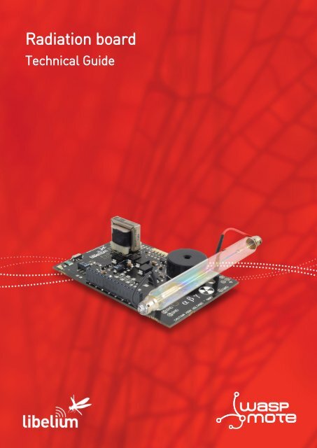
<strong>Radiation</strong> <strong>board</strong>Technical Guidewaspmote
IndexDocument version: v4.1 - 04/2013© <strong>Libelium</strong> Comunicaciones Distribuidas S.L.INDEX1. General.................................................................................................................................................. 41.1. General and safety information...............................................................................................................................................41.2. Conditions of use..........................................................................................................................................................................42. Waspmote Plug & Sense!...................................................................................................................... 52.1. Features............................................................................................................................................................................................52.2. Sensor Probes.................................................................................................................................................................................52.3. Solar Powered................................................................................................................................................................................62.4. Programming the Nodes............................................................................................................................................................72.5. Radio Interfaces.............................................................................................................................................................................82.6. Program in minutes......................................................................................................................................................................92.7. Data to the Cloud..........................................................................................................................................................................92.8. Meshlium Storage Options.....................................................................................................................................................102.9. Meshlium Connection Options............................................................................................................................................102.10. Models.........................................................................................................................................................................................112.10.1. <strong>Radiation</strong> Control......................................................................................................................................................123. Hardware............................................................................................................................................. 133.1. General description...................................................................................................................................................................133.2. Specifications..............................................................................................................................................................................143.3. Electrical characteristics..........................................................................................................................................................154. Sensors................................................................................................................................................ 174.1. <strong>Radiation</strong> sensor. Geiger-Müller tube J305ß....................................................................................................................174.1.1. Specifications................................................................................................................................................................174.1.2. Measurement process...............................................................................................................................................174.1.3. Socket..............................................................................................................................................................................185. Board configuration and programming .......................................................................................... 205.1. Hardware configuration..........................................................................................................................................................205.2. Waspmote Libraries...................................................................................................................................................................215.3. Code examples and extended information......................................................................................................................226. Consumption...................................................................................................................................... 246.1. Power control..............................................................................................................................................................................246.2. Tables of consumption.............................................................................................................................................................247. Documentation changelog................................................................................................................ 25-2- v4.1
General1. General1.1. General and safety information••In this section, the term “Waspmote” encompasses both the Waspmote device itself and its modules and sensor <strong>board</strong>s.••Read through the document “General Conditions of <strong>Libelium</strong> Sale and Use”.••Do not allow contact of metallic objects with the electronic part to avoid injuries and burns.••NEVER submerge the device in any liquid.••Keep the device in a dry place and away from any liquid which may spill.••Waspmote consists of highly sensitive electronics which is accessible to the exterior, handle with great care and avoid bangsor hard brushing against surfaces.••Check the product specifications section for the maximum allowed power voltage and amperage range and consequentlyalways use a current transformer and a battery which works within that range. <strong>Libelium</strong> is only responsible for the correctoperation of the device with the batteries, power supplies and chargers which it supplies.••Keep the device within the specified range of temperatures in the specifications section.••Do not connect or power the device with damaged cables or batteries.••Place the device in a place only accessible to maintenance personnel (a restricted area).••Keep children away from the device in all circumstances.••If there is an electrical failure, disconnect the main switch immediately and disconnect that battery or any other power supplythat is being used.••If using a car lighter as a power supply, be sure to respect the voltage and current data specified in the “Power Supplies” section.••If using a battery in combination or not with a solar panel as a power supply, be sure to use the voltage and current dataspecified in the “Power supplies” section of Waspmote technical guide.••If a software or hardware failure occurs, consult the <strong>Libelium</strong> Web Development section.••Check that the frequency and power of the communication radio modules together with the integrated antennas are allowedin the area where you want to use the device.••Waspmote is a device to be integrated in a casing so that it is protected from environmental conditions such as light, dust,humidity or sudden changes in temperature. The <strong>board</strong> supplied “as is” is not recommended for a final installation as theelectronic components are open to the air and may be damaged.••<strong>Radiation</strong> <strong>board</strong> contains high voltage parts (500V and above). Do not touch them directly with hand or with any object underany circumstances. There is a high voltage risk.••Geiger-Müller tube is the most sensitive part of radiation <strong>board</strong>. Never touch metallic tube contacts and do not hold the <strong>board</strong>by the Geiger tube because it can be permanently damaged.1.2. Conditions of use••Read the “General and Safety Information” section carefully and keep the manual for future consultation.••Use Waspmote in accordance with the electrical specifications and the environment described in the “Electrical Data”section of this manual.••Waspmote and its components and modules are supplied as electronic <strong>board</strong>s to be integrated within a final product. Thisproduct must contain an enclosure to protect it from dust, humidity and other environmental interactions. In the event ofoutside use, this enclosure must be rated at least IP-65.••Do not place Waspmote in contact with metallic surfaces; they could cause short-circuits which will permanently damage it.••Never touch Geiger-Müller tube poles directly with hands or using any metallic object under any circumstance. Tube polesworks with high voltages (up to 500V) which can produce spikes if they are touched. Internal circuits of radiation <strong>board</strong> andeven the user could be seriously affected.Further information you may need can be found at:http://www.libelium.com/development/waspmoteThe “General Conditions of <strong>Libelium</strong> Sale and Use” document can be found at:http://www.libelium.com/development/waspmote/technical_service-4- v4.1
Waspmote Plug & Sense!2.3. Solar PoweredBattery can be recharged using the internal or external solar panel options.The external solar panel is mounted on a 45º holder which ensures the maximum performance of each outdoor installation.Figure 2: Waspmote Plug & Sense! powered by an external solar panelFor the internal option, the solar panel is embedded on the front of the enclosure, perfect for use where space is a majorchallenge.Figure 3: Internal solar panel-6- v4.1
Waspmote Plug & Sense!Figure 4: Waspmote Plug & Sense! powered by an internal solar panel2.4. Programming the NodesWaspmote Plug & Sense! can be reprogrammed in two ways:The basic programming is done from the USB port. Just connect the USB to the specific external socket and then to the computerto upload the new firmware.Figure 5: Programming a node-7- v4.1
Waspmote Plug & Sense!Over the Air Programming is also possible once the node has been installed. With this technique you can reprogram wirelesslyone or more Waspmote sensor nodes at the same time by using a laptop and the Waspmote Gateway.Figure 6: Typical OTAP process2.5. Radio InterfacesModel Protocol Frequency txPower Sensitivity Range *XBee-802.15.4-Pro 802.15.4 2.4GHz 100mW -100dBm 7000mXBee-ZB-Pro ZigBee-Pro 2.4GHz 50mW -102dBm 7000mXBee-868 RF 868MHz 315mW -112dBm 12kmXBee-900 RF 900MHz 50mW -100dBm 10KmWifi 802.11b/g 2.4GHz 0dBm - 12dBm -83dBm 50m-500mGPRS - 850MHz/900MHz/ 2W(Class4) 850MHz/900MHz, -109dBm1800MHz/1900MHz 1W(Class1) 1800MHz/1900MHz3G/GPRS - Tri-Band UMTS2100/1900/900MHzQuad-Band GSM/EDGE,850/900/1800/1900 MHzUMTS 900/1900/2100 0,25WGSM 850MHz/900MHz 2WDCS1800MHz/PCS1900MHz 1W-106dBm* Line of sight and Fresnel zone clearance with 5dBi dipole antenna-8- v4.1
Waspmote Plug & Sense!2.6. Program in minutesIn order to program the nodes an intuitive graphic interface has been developed. Developers just need to fill a web form inorder to obtain the complete source code for the sensor nodes. This means the complete program for an specific applicationcan be generated just in minutes. Check the Code Generator to see how easy it is at:http://www.libelium.com/development/plug_&_sense/sdk_and_applications/code_generatorFigure 7: Code Generator2.7. Data to the CloudThe Sensor data gathered by the Waspmote Plug & Sense! nodes is sent to the Cloud by Meshlium, the Gateway router speciallydesigned to connect Waspmote sensor networks to the Internet via Ethernet, Wifi and 3G interfaces.Thanks to Meshlium’s new feature, the Sensor Parser, now it is easier to receive any frame, parse it and store the data into a localor external Data Base.Figure 8: Meshlium-9- v4.1
Waspmote Plug & Sense!2.8. Meshlium Storage Options• Local Data Base• External Data Base2.9. Meshlium Connection Options• ZigBee → Ethernet• ZigBee → Wifi• ZigBee → 3G/GPRS-10- v4.1
Waspmote Plug & Sense!2.10. ModelsThere are some defined configurations of Waspmote Plug & Sense! depending on which sensors are going to be used. WaspmotePlug & Sense! configurations allows connecting up to six sensor probes at the same time.Each model takes a different conditioning circuit to enable the sensor integration. For this reason each model allows to connectjust its specific sensors.This section describes each model configuration in detail, showing the sensors which can be used in each case and how toconnect them to Waspmote. In many cases, the sensor sockets accept the connection of more than one sensor probe. See thecompatibility table for each model configuration to choose the best probe combination for the application.It is very important to remark that each socket is designed only for one specific sensor, so they are not interchangeable.Always be sure you connected probes in the right socket, otherwise they can be damaged.ABCDEFFigure 9: Identification of sensor sockets-11- v4.1
Waspmote Plug & Sense!2.10.1. <strong>Radiation</strong> ControlThe main application for this Waspmote Plug & Sense! configuration is to measure radiation levels using a Geiger sensor. Forthis model, the Geiger tube is already included inside Waspmote, so the user does not have to connect any sensor probe to theenclosure. The rest of the other sensor sockets are not used.Figure 10: <strong>Radiation</strong> Control Waspmote Plug & Sense! modelSensor sockets are not used for this model.Note: For more technical information about each sensor probe go to the Development section in <strong>Libelium</strong> website.-12- v4.1
Hardware3. Hardware3.1. General description<strong>Radiation</strong> sensor <strong>board</strong> is based on a Geiger-Müller tube. Most detectors include an audio amplifier that produce an audible click ondischarge. The number of pulses per second measures the intensity of the radiation field. Some Geiger counters display an exposure rate(e.g. mR·h), but this does not relate easily to a dose rate as the instrument does not discriminate between radiation of different energies.The usual form of Geiger-Müller tube is an end-window tube. This type is so-named because the tube has a window at one endthrough which ionizing radiation can easily penetrate. The other end normally has the electrical connectors. There are two types ofend-window tubes: the glass-mantle type and the mica window type. The glass window type will not detect alpha radiation since itis unable to penetrate the glass, but is usually cheaper and will usually detect beta radiation and X-rays. The mica window type willdetect alpha radiation but is more fragile.Most tubes will detect gamma radiation, and usually beta radiation above about 2.5 MeV. Geiger–Müller tubes will not normallydetect neutrons since these do not ionize the gas. However, neutron-sensitive tubes can be produced which either have the insideof the tube coated with boron or contain Boron trifluoride or Helium-3 gas. The neutrons interact with the boron nuclei, producingalpha particles or with the Helium-3 nuclei producing Hydrogen and Tritium ions and electrons. These charged particles then triggerthe normal avalanche process.Although most tubes will detect gamma radiation, standard tubes are relatively inefficient, as most gamma photons will pass throughthe low density gas without interacting. Using the heavier noble gases Krypton or Xenon for the fill effects a small improvement, butdedicated gamma detectors use dense cathodes of lead or stainless steel in windowless tubes. The dense cathode then interacts withthe gamma flux, producing high-energy electrons, which are then detected.A Geiger counter, also called a Geiger-Müller counter, is a type of particle detector that measures ionizing radiation. They detect theemission of nuclear radiation: alpha particles, beta particles or gamma rays. A Geiger counter detects radiation by ionization producedin a low-pressure gas. Each particle detected produces a pulse of current, but the Geiger counter cannot distinguish the energy of thesource particles. Geiger counters are popular instruments used for measurements in health physics, industry, geology and other fields,because they can be made with simple electronic circuits.Modern instruments can report radioactivity over several orders of magnitude. Some Geiger counters can be used to detect gammaradiation, though sensitivity can be lower for high energy gamma radiation than with certain other types of detectors. The density ofgas in the device is usually low, allowing most high energy gamma photons to pass through undetected. Lower energy photons areeasier to detect, and are better absorbed by the detector. Examples of this are the X-ray Pancake Geiger Tube.Waspmote radiation <strong>board</strong> has two main parts, power circuit and signal circuit. The power part is used to provide necessary voltage forGeiger-Müller tube (~370V) and the signal circuit is used to adapt the pulses produced by the tube and connect them to microcontrollerinput.Once the tube is powered, pulses can be received by Waspmote and can be counted. Then, radiation value is obtained with an easycalculation.Code used for radiation <strong>board</strong> is counting pulses during 10 seconds and then, number of pulses is multiplied by 6, so number of pulsesper minute (cpm) is obtained. Besides that, according to tube documentation cpm is multiplied by a conversion factor of 0.00812037to obtain radiation value in µSV/h.-13- v4.1
Hardware3.2. SpecificationsWeight: 50grDimensions: 92 x 60 x 1.3 mmTemperature Range: [-20ºC, 65ºC]Electronic components used in the radiation <strong>board</strong> can be divided in next parts:1. High voltage power supplyHigh voltage power supply uses a circuit based on an oscillator connected to a voltage multiplier made with diodes,transistors, resistors and capacitors (see schematic for detail).2. Adaptation circuit for the Geiger outputThe adaptation circuit for the output is based on a NPN transistor, this transistor will trigger the interrupt pin in theWaspmote microcontroller which make the interrupt routine associated to be executed, adding one to the current counter.Even this transistor is also activating/deactivating the piezo speaker and LED indicator generating the audio/visual signal.3. Piezo speaker and LED indicatorThe piezo speaker and LED indicator are connected to the adaptation circuit, so LED will blink with each pulse and speakerwill sound with each pulse.4. LED barLED bar is made with five standard LEDs, 3 green and 2 red. These leds are connected to digital pins of the microconrollerwith a series resistor. LED bar can be configured in order to give a visual information of the measured radioactivity level.Default configuration (loaded in the Waspmote API example) is predefined for next threshold values in cpm units.<strong>Radiation</strong> value (cpm)LED barValue < 75OFF75 < Value < 150 1 Green LED150 < Value < 400 2 Green LED400 < Value < 600 3 Green LED600 < Value < 900 3 Green LED, 1 Red LEDValue > 9003 Green LED, 2 Red LEDIn addition, LED bar can be handled by changing state of corresponding Waspmote pin, using functions likedigitalWrite(pin,state), defined into Waspmote API. Digital pin numbers are described during this guide.All described parts and their <strong>board</strong> location are shown in next figure.Figure 11: Parts of the radiation <strong>board</strong>-14- v4.1
Hardware3.3. Electrical characteristicsBoard power voltages: 5V / 3V3Geiger-Müller tube power voltage: 370VMaximum admitted current (continuous): 200mAMaximum admitted current (peak): 300mASpeaker: 95dB, 3.4KHzExternal ON/OFF switch.LED bar with 5 leds (3 green and 2 red).Next figure shows schematic of radiation <strong>board</strong>.-15- v4.1
HardwareFigure 12: <strong>Radiation</strong> <strong>board</strong> schematic-16- v4.1
Sensors4. Sensors4.1. <strong>Radiation</strong> sensor. Geiger-Müller tube J305ß4.1.1. SpecificationsManufacturer: North Optic<strong>Radiation</strong> Detection: Beta, Gamma [β, γ]Length: 111mmDiameter: 11mmRecommended Voltage: 350VPlateau Voltage: 360-440VSensitivity γ (60Co): 65cps/(µR/s)Sensitivity γ (equivalent Sievert): 108cpm / (µSv/h)Max cpm: 30000cps/mR/h: 18cpm/m/h: 1080cpm/µSv/h: 123.147092360319Factor: 0.00812037037037Figure 13: North Optic Geiger-Müller TubeWarning: Never touch Geiger-Müller tube ends directly with hands or using any metallic object under any circumstance. Tubeends works with high voltages (up to 500V) which can produce spikes if they are touched. Internal circuits of radiation <strong>board</strong> andeven the user could be seriously affected.Note: the Geiger tube should not be exposed to sunlight because the CPM may not be as accurate as indoors. We advise to use anopaque enclosure when working outdoors to cover this sensor.4.1.2. Measurement process<strong>Radiation</strong> sensor <strong>board</strong> is based on a Geiger-Müller tube, which consists of a tube filled with a low-pressure (~0.1 Atm) inert gassuch as Helium, Neon or argon (usually neon), in some cases in a penning mixture, and an organic vapor or a halogen gas. Thetube contains electrodes, between which there is a potential difference of several hundred volts, but no current flowing. Thewalls of the tube are either entirely metal or have their inside surface coated with a conductor to form the cathode while theanode is a wire passing up the center of the tube.When ionizing radiation passes through the tube, some of the gas molecules are ionized, creating positively charged ions, andelectrons. The strong electric field created by the tube’s electrodes accelerates the ions towards the cathode and the electronstowards the anode. The ion pairs gain sufficient energy to ionize further gas molecules through collisions on the way, creatingan avalanche of charged particles.This results in a short, intense pulse of current which passes (or cascades) from the negative electrode to the positive electrodeand is measured or counted.There are three types or radioactive particles, Alpha, Beta and Gamma which are generated in the nuclear power plants, Butthe Geiger-Müller tube of the Waspmote radiation <strong>board</strong> only measures Beta and Gamma particles.-17- v4.1
SensorsMore information about radioactive particles and how to measure them can be obtained following link:http://www.cooking-hacks.com/index.php/documentation/tutorials/geiger-counter-arduino-radiation-sensor-<strong>board</strong>From counts per minute (cpm) to SievertsMeasured units by Geiger Tubes are basically the number of pulses generated. This means that in one second there will be “n”counts (counts per second - cps) and in 1 minute the counts per minute (cpm). This value is common for all the Geiger Tubes,however, it is not an energy value but just the number of pulses. In order to get the real energy irradiated and the amount thatis absorbed by a body this value should be converted to Sieverts per hour.The formula which passes from cpm to Sieverts depends mostly on the Geiger Tube: size, shape, material, sensibility, dead time,type of particle measured, etc. Normally a conversion factor can be extracted from the charts provided by the manufacturer inthe calibration process:cpm * conversion factor = μSv/hFor example, the conversion factor for the J305ß tube is 0.00812037. This means that detecting 120cpm will have the next value.J305ß: 120 * 0.008120370 = 0,9744μSv/hNote: This conversion factor is extracted by the manufacturer in the calibration process. However, this value is only accurate when theelement which is radiating is the same as the one used in the calibration process eg: 137 Cs, 60 Co.4.1.3. Socket<strong>Radiation</strong> <strong>board</strong> is connected to waspmote using connector 1 and connector 2, as is shown in figure below. They are connectedto Sensor I/O and I2C/UART connectors of Waspmote respectively. See Waspmote technical guide for a detailed description ofWaspmote connectors.Figure 14: Connectors used with Waspmote <strong>board</strong>-18- v4.1
SensorsMoreover, the Geiger-Müller tube is connected to the radiation <strong>board</strong> using socket 1, by two pins (positive and GND). Nextfigure shows it in detail.Figure 15: Connexion of Geiger tube to radiation <strong>board</strong>-19- v4.1
5. Board configuration and programming5.1. Hardware configurationBoard configuration and programmingThe radiation <strong>board</strong> has a dedicated ON/OFF switch. In order to power on the <strong>Radiation</strong> Sensor Board, place its switch in therequired position as shown in next image:Figure 16: External ON / OFF switchTake into account that radiation <strong>board</strong> can be switched ON/OFF also by software. Therefore if radiation <strong>board</strong> is powered bysoftware, dedicated external switch must be in the ON position. The state of the <strong>board</strong> can be known looking for the ledplaced close to the external switch. If led is ON, <strong>board</strong> will be therefore ON.<strong>Radiation</strong> <strong>board</strong> is powered by 5V power pin of the I/O sensor connector. However, the output is adapted to 3V3 to be able toread values with Waspmote.Moreover, there are several indicators on the radiation <strong>board</strong> used to show radiation levels to the user. A LED and a piezospeaker are connected to the Geiger tube output. The piezo speaker will play one audible sound, one “click” for each particlecounted and the LED will blink also one time for each particle.In addition, there is a LED bar (3 green LEDs and 2 red LEDs) which can be controlled directly by Waspmote. LED bar is connectedto these digital pins:LEDLED green 0LED green 1LED green 2LED red 0LED red 1PINDIGITAL8DIGITAL6DIGITAL4DIGITAL2DIGITAL3This bar can be configured in order to give a visual information of the measured radioactivity level. Default configuration(loaded in the Waspmote API example) is predefined for threshold values in cpm units described in 2.1, but can be easilymodified by changing the code.-20- v4.1
Board configuration and programming5.2. Waspmote LibrariesWaspmote radiation <strong>board</strong> has its own library where necessary functions are included to handle interruptions and other eventsof the <strong>board</strong>. The corresponding files are Wasp<strong>Radiation</strong>.h and Wasp<strong>Radiation</strong>.cpp.To start using Waspmote <strong>Radiation</strong> library, an object from class Wasp<strong>Radiation</strong> must be created. This object, called <strong>Radiation</strong>, iscreated inside Waspmote <strong>Radiation</strong> library and it is public to all libraries. It is used through this guide to show how Waspmote<strong>Radiation</strong> library works.When creating this constructor, all the variables are defined with an initial value by default.All radiation <strong>board</strong> API functions are listed below.In the Waspmote Development section you can find complete examples about using this <strong>board</strong>.Go to: http://www.libelium.com/development/waspmote/examplesON()This function powers radiation <strong>board</strong> by the internal solid state switch. External switch must be ON.OFF()This function removes power supply from radiation <strong>board</strong>.init()This function enables radiation <strong>board</strong> interrupts and test the led bar indicator by turning on all leds.get<strong>Radiation</strong>()<strong>Radiation</strong> value is measured during 10 seconds. After that, some calculations are done to obtain the cpm and μSv/h values. Italso manages interruptions caused by measured pulses of the radiation <strong>board</strong>.<strong>Radiation</strong> value can be also read by checking public variable “radiationValue”.get<strong>Radiation</strong>Int()It is equal to the previous one but managing interruptions directly inside this function.get<strong>Radiation</strong>Int(time)<strong>Radiation</strong> value is measured during specified time. This time must be in milliseconds and also less than 60 seconds. After that,some calculations are done to obtain the cpm and the μSv/h values. It also manages interruptions caused by measured pulsesof the radiation <strong>board</strong>. <strong>Radiation</strong> value is returned but also it can be read by checking public variable “radiationValue”.getCPM(time)This function does the same as “get<strong>Radiation</strong>()” but the returned value is in cmp units. In addition, value can be read by checkingpublic variable “radiationvalueCPM”countPulse()Adds one pulse to the pulse counter.ledBar(int value)Refreshes led bar value according measured value. User can modify LED bar value whenever, but always according to definedthreshold levels.The Geiger tube output is connected to RXD1 pin to make an interrupt every generated pulse. Besides that, the output isconnected to DIGITAL 7 pin on order to monitor when an interrupt takes place.In addition, the conversion factor is defined as a constant named CONV_FACTOR, with a default value of 0.008120. This constantis used to convert cpm units into μSv/h. The user is free to adjust this value by changing the value of this constant, defined atthe beginning of the radiation <strong>board</strong> header source file.-21- v4.1
5.3. Code examples and extended informationAn example code using the radiation <strong>board</strong> and the Waspmote response through USB is listed below.Board configuration and programmingIn the Waspmote Development section you can find complete examples about using this <strong>board</strong>.Go to: http://www.libelium.com/development/waspmote/examplesWaspmote example code:/** -------------------- RB.1 – Reading radiation in cpm -------------------** Explanation: This example shows how to read radiation in CPM** Copyright (C) 2012 <strong>Libelium</strong> Comunicaciones Distribuidas S.L.* http://www.libelium.com** This program is free software: you can redistribute it and/or modify* it under the terms of the GNU General Public License as published by* the Free Software Foundation, either version 3 of the License, or* (at your option) any later version.** This program is distributed in the hope that it will be useful,* but WITHOUT ANY WARRANTY; without even the implied warranty of* MERCHANTABILITY or FITNESS FOR A PARTICULAR PURPOSE. See the* GNU General Public License for more details.** You should have received a copy of the GNU General Public License* along with this program. If not, see .** Version: 0.1* Design: David Gascón* Implementation: Javier Siscart*/#include “WaspSensor<strong>Radiation</strong>.h”void setup(){}// Starting USBUSB.ON();USB.println(F(“Starting Waspmote...”));// Starting <strong>Radiation</strong> Board<strong>Radiation</strong>Board.ON();void loop(){}// Variable to store measured radiationfloat radiation;// Measure radiation in cpm, during 5sUSB.println(F(“Measuring during 5s cpm”));radiation = <strong>Radiation</strong>Board.getCPM(5000);USB.print(F(“radiation[cpm]: “));USB.println(radiation);USB.println();delay(2000);-22- v4.1
Board configuration and programmingWaspmote response:Starting Waspmote...Measuring during 5s cpmradiation[cpm]: 60.0000000000Measuring during 5s cpmradiation[cpm]: 72.0000000000-23- v4.1
Consumption6. Consumption6.1. Power controlThe power of the radiation <strong>board</strong> is drawn from the Waspmote and it is controlled by two ways. One way is using externalswitch and the other one is Waspmote internal solid state switches which are accessed through the 2x11 connector, defined asSENS_5V and SENS_3V3 in the application. From solid state switch it is therefore possible to completely activate or deactivatethe <strong>board</strong> power always taking into account the external switch position (see Waspmote manual for more details about theswitches to manage the mote’s power and the appropriate section in Waspmote API manual’s library for more informationon its handling).6.2. Tables of consumptionNext table shows the power consumption of Waspmote radiation <strong>board</strong>.Minimum (constant)Consumption11.9 mAIn addition, each pulse of Geiger tube can produce pulses of current up to 0.05 mA.-24- v4.1
Documentation changelog7. Documentation changelog••Added references to 3G/GPRS Board in section: Radio Interfaces.-25- v4.1
Maintenance8. MaintenanceIn this section, the term “Waspmote” encompasses both the Waspmote device itself as well as its modules and sensor <strong>board</strong>s.••Take care with the handling of Waspmote, do not drop it, bang it or move it sharply.••Avoid putting the devices in areas of high temperatures since the electronic components may be damaged.••The antennas are lightly threaded to the connector; do not force them as this could damage the connectors.••Do not use any type of paint for the device, it may harm the functioning of the connections and closing mechanisms.7.-26- v4.1
Disposal and recycling9. Disposal and recyclingIn this section, the term “Waspmote” encompasses both the Waspmote device itself as well as its modules and sensor <strong>board</strong>s.••When Waspmote reaches the end of its useful life, it must be taken to a recycling point for electronic equipment.••The equipment has to be disposed on a selective waste collection system, different to that of urban solid waste. Please,dispose it properly.••Your distributor will inform you about the most appropriate and environmentally friendly waste process for the usedproduct and its packaging.-27- v4.1