Radiation board - Libelium
Radiation board - Libelium
Radiation board - Libelium

You also want an ePaper? Increase the reach of your titles
YUMPU automatically turns print PDFs into web optimized ePapers that Google loves.
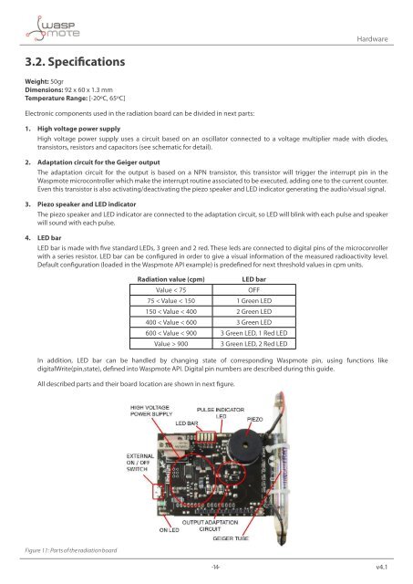
Hardware3.2. SpecificationsWeight: 50grDimensions: 92 x 60 x 1.3 mmTemperature Range: [-20ºC, 65ºC]Electronic components used in the radiation <strong>board</strong> can be divided in next parts:1. High voltage power supplyHigh voltage power supply uses a circuit based on an oscillator connected to a voltage multiplier made with diodes,transistors, resistors and capacitors (see schematic for detail).2. Adaptation circuit for the Geiger outputThe adaptation circuit for the output is based on a NPN transistor, this transistor will trigger the interrupt pin in theWaspmote microcontroller which make the interrupt routine associated to be executed, adding one to the current counter.Even this transistor is also activating/deactivating the piezo speaker and LED indicator generating the audio/visual signal.3. Piezo speaker and LED indicatorThe piezo speaker and LED indicator are connected to the adaptation circuit, so LED will blink with each pulse and speakerwill sound with each pulse.4. LED barLED bar is made with five standard LEDs, 3 green and 2 red. These leds are connected to digital pins of the microconrollerwith a series resistor. LED bar can be configured in order to give a visual information of the measured radioactivity level.Default configuration (loaded in the Waspmote API example) is predefined for next threshold values in cpm units.<strong>Radiation</strong> value (cpm)LED barValue < 75OFF75 < Value < 150 1 Green LED150 < Value < 400 2 Green LED400 < Value < 600 3 Green LED600 < Value < 900 3 Green LED, 1 Red LEDValue > 9003 Green LED, 2 Red LEDIn addition, LED bar can be handled by changing state of corresponding Waspmote pin, using functions likedigitalWrite(pin,state), defined into Waspmote API. Digital pin numbers are described during this guide.All described parts and their <strong>board</strong> location are shown in next figure.Figure 11: Parts of the radiation <strong>board</strong>-14- v4.1