

Cyclone Electric Start Kit - Vintage Snow
Cyclone Electric Start Kit - Vintage Snow
Cyclone Electric Start Kit - Vintage Snow

You also want an ePaper? Increase the reach of your titles
YUMPU automatically turns print PDFs into web optimized ePapers that Google loves.
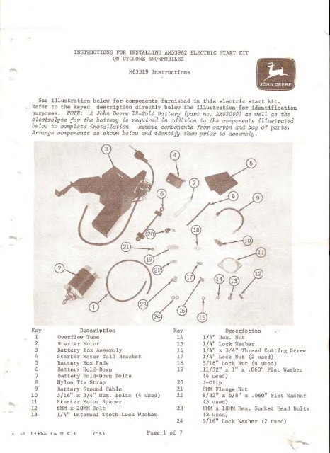
INSTRUC TIONS FOR INSTALLING AM53962 ELECTRIC START KITON CYCLONE SNOWMOBILESM63319 InstructionsSee illustration bel ow for components f urnished in this electric start kit.Refer to t he ke yed description directly bel ow the i llustration for identificationpurposes . NOTE: A John Deere l2 -VoU Battery (papt no. AM52050J as well as theelectrolyte for the battery is r equi red in addition to the components illustratedbelow to compl-et-e installation. Remove oomponente from carton and bag of parte,APrange components as sho-wn below and identify them pr-ior to assembly.Key1234567B910111213DescriptionOverflow Tube<strong>Start</strong>er MotorBattery Box Assembly<strong>Start</strong>er Motor Tail BracketBattery Box PadsBattery Ho ld-DownBattery Hold-Down BoltsNylon Tie StrapBattery Gro und Cable5/16" x 3/ 4" Hex. Bolts (4 used)<strong>Start</strong>er Motor Spacer6MM x 20MM Bolt1/4" Internal Tooth Lock WasherKey1415161718192021222324Description1/4 11 Hex. Nut1/4" Lock Washer1/4" x 3/4" Thread Cutting Screw1/4" Lock Nut (2 used)5/16 11 Lock Nut (4 used)11/32" x 1" x .060" Flat Washer(4 used)J-Clip811M Flange Nut9/32 11 x 5/8" X(5 us ed). 060 11 Flat WasherBMM x lBMM Hex. Socket Head Bol t s(2 used)5/16 11 Lock Washer (2 used)Pa2e 1 of 7
fREPARE SNOWMOBILE1. Unlatch hood. Raise hood completelyforward as shown ahove.2 . Disconnect four springs securingt he muffler in place. Remove muffler.3 . Remove drive be l t shield lat chpin. Place dr i ve belt shield fo rward.4 . Remove drive belt from secondarydr ive sheave.5. Remove primary drive cl utch sheavewith special tools JDM 12-2, JDM 41-2,and JDM 41-4 as shown in the snowmobileservice manual .6. Remove and discard the hex. nutsand washers securing end cap t o enginehousing . Remove and discard end cap . .You now have the snowmobile completelyprepared. Now, refer to page 3 andbegin to install t he components of theelectric start kit .-2-
INSTALL TAIL BRACKET ON STARTER MOTORAND PREPARE BA'I"I'ERY FOR INSTALLATIONAf ter bat tery i s properly charged.add el ect rolyte unt i l level wi t h circular split l edge in fil ler t ube. Thereafter.add only distil l ed water to batteryas us e and t ime require .A'ITACH STARTER MOTOR TOENGINE1 . Attach tail bracket to starter motorwith a 1/4" x 3/4" thread cuttings crew.NOTE: Turn thread cutt ing screwal-l- the way into starter motor hole andthen back it out two or three turns.Leave the tail bracket loose until afterstarter motor is installed.2. Obtain a J ohn Deere battery (partno. AH52050) from stock. Sl i p over f l owtube over nipple on battery as shownabove.Remove ba t tery cell caps and addelectrolyte t o battery as explainedbe low.CAUTION: Battery eleot aolv te ispoi sonous and can be injurious toeyes, skin and olothing. Be carefULwhen adding eleotrolqte t o bat t ery .Use only battery grade sulfuricacid electrolyte with 1.265 s peci ficgravi ty pl us or minus 0.005 cor r e ctedto 80 degrees f ahrenheit.Use sp ecial pr ecaut i on when fillingthis small battery. Never place batteryin sno~bile before the electrolyte isadded. Pour in electrolyte slowlyuntil vi si bl e i n the bottom of eachf1lling tube . Then charge battery 15amps for 10 minutes or 7 amps for 30minutes. DO NOT EXCEED RECOMMENDEDCHARGING RATE.1 . Pl ace starter motor spacer overt he two stud bo l ts on engine hous ing.2. Insert drive gear end of startermotor into housing . Secur e s t art e rmotor to top stud bol t on housi ng withone 8 mm flange nut . Tighten nutsecurely.3. Bolt starter motor tail bracketto engine with two 5/16" lock washersand two 8 rom x 18 mm hex. socket headbolts. Tighten bolts securely.4. Tighten thread cut t i ng screw ontail bracket securely.- 3-
J-CLIP TOENGINE BOLT1 . Remove and save t he 6mm x 15 mm boltfrom r i ght-hand side of engine. BoltJ-~l ip to side of engi ne and fan shieldhousing with two 9/ 32" x 5/ 8" x .060" f latwashers and a 6 mm x 20 rom hex. headbolt.INSTALL BATTERY BOX ASSEMBLY,I3. Bolt r ear par t of battery boxmounting bracket to tunnel with two11/32" x 1" x . 060" flat washers. two5/16" x 3/4" hex. he ad bolts,and two5/16" lock nuts.Cut out paper template provided onpage 7. Cut out dashed line area ontemplate for locating and drillingholes in tunnel.1. Pla ce templ ate on tunnel as shownabove. Be sure template is flush withfront and right-hand edges of tunnel.2 . Us i ng a center punch and hammer,mark through the two . 344 holes ontemplate into tunnel . Remove templateand drill two 11/32" holes throughtl.alDel.NOTE: Aeeesdr l e fiat uaehere on boltsand i nsert bolts up from bottom oftunnel. Fla t washers must be beneathboZt heads to prevent the boZt headsf rom being pu Lled through the tunneL,4. Position front part of batterybox mounting bracket on tunnel as shownabove. Using holes in bracket as atemplate, drill two 11/32" holes throughtunnel. Bolt front battery box bracketto tunnel with two 11/32" x I" x .060"flat washers. two 5/16" x 3/4" he x. h eadbolts , and two 5/16" l ock nuts.,5. Place the two oattery box padsi n battery box as shown above.-4-
ATTACH RECTIFIER WIRE TO TERMINALBOARDCONNECT BATTERY BOX ASSEMBLY ELECTRICALWIRES TO MAIN WIRING HARNESS PLUG...1. Pull wiring harness connectoroff ignition switch t erminals.2. Pus h red wi re s pade terminal intotop left-hand access opening on r ear ofconnector plug.1. Place brown rectifier wire frombat tery box assembly i nt o J-clip wit hmain wi r ing harness .2 . Push female co nnector on rectifierwire onto open male s pade connectOr onalternator terminal.NOTE: The al-ternator terminal iethe second one open f rom t he left onthe t erminal: board,3 . Push orange wire spade terminalinto bottom right-hand access openi ngon rear of connector pl ug .4. Push purple wire spade terminalinto top right-hand access openin~ onrear of connector plug.Push main wiring harness connectorplug ont o ignition switch terminals .INSTALL BATTERY3. Secure r ectifier wire to mainwiring harness with nylon tie strap .-5-1. Install the two battery hold-downbolts through battery hold-down. Placetwo 9/32 11x 518" x . 060" flat washerand two 1/4" lock nuts on hold-downbolts. Leave lock nuts loose.
2. Place battery in battery box withpositive (+) t erminal on battery facingforward .3. Place battery hold-down with boltson top of battery. Hook ends of holddownbolts in s l ot s on front and rearof battery box as shown above.4. Tighten l ock nuts on battery holddownbol ts snug. Do not over-tighten.5. Place s tarter solenoid cable i nJ-clip a t tached to right-hand s i de ofengine . At tach solenoid cable tostar ter mo t or with a 1/4 11 internal toothlock washer and 1/4 11hex. nut.6. Pla ce end of overflow t ube frombattery thr ough hole in bottom of tunnel.7 . At t ach positive (+) battery cableto posi t ive t erminal on batt ery.8. Using 6 mm x l : -mm bolt previouslyremoved i n step l ~ on page 4~ place a9/32" x 5/ 8" x .060" flat washer on boltand attach negative (-) gr ound cable toCAUTION : To avoid aaaident-al- shortairauiting, be sure to atrtaah the positivecable to positive (+) batteryterminal before the ground cable isattached to the negative (-) battery s i de of engine as shown.terminal. Slide rubber boot over positi ve battery terminal- unbi: l t erminal andat taching bolt are conpktely covered.- 6-At t ach otherend of cabl e to negative (-) batteryterminal.
.REINSTALL PARTS REMOVEDYou now have the electric start kitins talled.Now, r ei ns t a l l the primary drivecl utch sheave , drive belt, mufflerand latch the drive belt shield inplace.IMPORTANT: Be sure to tight en theprirrary drive cl-utch: sheave bolt to50 ft-lbs torque ,Lower and latch the hood in place.Refer to the Operator's Manual forcomplete starting instructions andbattery maintenance.TEMPLATEUse the template shown below forlocating the two holes t hat must bedrilled in the tunnel t o install thebattery box assembly.T,-----I IL_----R.H. EDGE OF TUNNELI--FRONT EDGE OF TUNNEL-- .....I + ,...-}-121.344 HOLES;oJ\ t ' _I- 7-
fI"--. 7 7!,. ~'g",


