Catalog IC 10 English 2011 - Industry
Catalog IC 10 English 2011 - Industry
Catalog IC 10 English 2011 - Industry

Create successful ePaper yourself
Turn your PDF publications into a flip-book with our unique Google optimized e-Paper software.
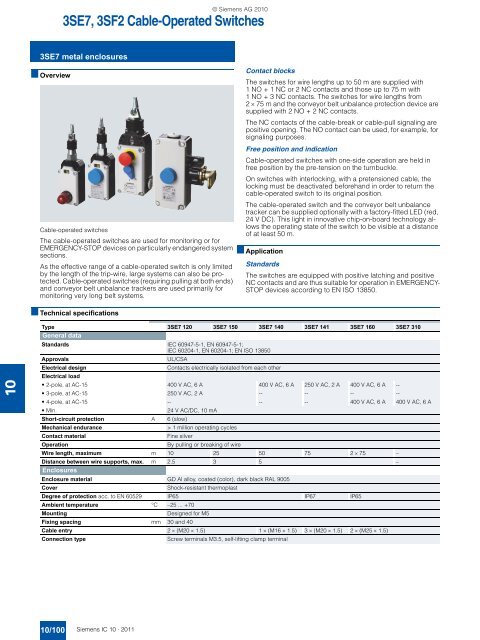
© Siemens AG 20<strong>10</strong>3SE7, 3SF2 Cable-Operated Switches3SE7 metal enclosures■ OverviewCable-operated switchesThe cable-operated switches are used for monitoring or forEMERGENCY-STOP devices on particularly endangered systemsections.As the effective range of a cable-operated switch is only limitedby the length of the trip-wire, large systems can also be protected.Cable-operated switches (requiring pulling at both ends)and conveyor belt unbalance trackers are used primarily formonitoring very long belt systems.■ Technical specificationsContact blocksThe switches for wire lengths up to 50 m are supplied with1 NO + 1 NC or 2 NC contacts and those up to 75 m with1 NO + 3 NC contacts. The switches for wire lengths from2 × 75 m and the conveyor belt unbalance protection device aresupplied with 2 NO + 2 NC contacts.The NC contacts of the cable-break or cable-pull signaling arepositive opening. The NO contact can be used, for example, forsignaling purposes.Free position and indicationCable-operated switches with one-side operation are held infree position by the pre-tension on the turnbuckle.On switches with interlocking, with a pretensioned cable, thelocking must be deactivated beforehand in order to return thecable-operated switch to its original position.The cable-operated switch and the conveyor belt unbalancetracker can be supplied optionally with a factory-fitted LED (red,24 V DC). This light in innovative chip-on-board technology allowsthe operating state of the switch to be visible at a distanceof at least 50 m.■ ApplicationStandardsThe switches are equipped with positive latching and positiveNC contacts and are thus suitable for operation in EMERGENCY-STOP devices according to EN ISO 13850.<strong>10</strong>Type 3SE7 120 3SE7 150 3SE7 140 3SE7 141 3SE7 160 3SE7 3<strong>10</strong>General dataStandards IEC 60947-5-1, EN 60947-5-1;IEC 60204-1, EN 60204-1; EN ISO 13850ApprovalsUL/CSAElectrical designContacts electrically isolated from each otherElectrical load• 2-pole, at AC-15 400 V AC, 6 A 400 V AC, 6 A 250 V AC, 2 A 400 V AC, 6 A --• 3-pole, at AC-15 250 V AC, 2 A -- -- -- --• 4-pole, at AC-15 -- -- -- 400 V AC, 6 A 400 V AC, 6 A•Min.24 V AC/DC, <strong>10</strong> mAShort-circuit protection A 6 (slow)Mechanical endurance> 1 million operating cyclesContact materialFine silverOperationBy pulling or breaking of wireWire length, maximum m <strong>10</strong> 25 50 75 2 × 75 –Distance between wire supports, max. m 2.5 3 5 –EnclosuresEnclosure material GD Al alloy, coated (color), dark black RAL 9005CoverShock-resistant thermoplastDegree of protection acc. to EN 60529 IP65 IP67 IP65Ambient temperature °C –25 ... +70MountingDesigned for M5Fixing spacing mm 30 and 40Cable entry 2 × (M20 × 1.5) 1 × (M16 × 1.5) 3 × (M20 × 1.5) 2 × (M25 × 1.5)Connection typeScrew terminals M3.5, self-lifting clamp terminal<strong>10</strong>/<strong>10</strong>0 Siemens <strong>IC</strong> <strong>10</strong> · <strong>2011</strong>