Tensinews 21 - sept2011 - vers 31-8 - TensiNet
Tensinews 21 - sept2011 - vers 31-8 - TensiNet
Tensinews 21 - sept2011 - vers 31-8 - TensiNet

You also want an ePaper? Increase the reach of your titles
YUMPU automatically turns print PDFs into web optimized ePapers that Google loves.
RESEARCH<br />
2 Minimal surfaces between<br />
boundaries consisting of<br />
segments of a circle<br />
In this case the boundaries of wall like Minimal<br />
Surfaces can have the same direction or they<br />
can be arranged in<strong>vers</strong>ely. Horizontally shifted<br />
boundaries represent special cases and show<br />
interesting architectural effects. The horizontal<br />
offset can be in longitudinal, cross or diagonal<br />
direction.<br />
Minimal Surfaces between boundaries<br />
consisting of segments of a circle<br />
in the same direction<br />
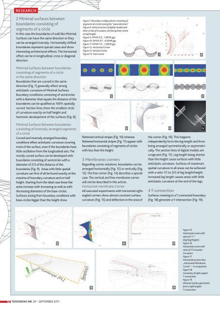
Boundaries that are curved in the same<br />
direction (Fig. 7) generally effect strong<br />
anticlastic curvature of Minimal Surfaces.<br />
Boundary conditions consisting of semicircles<br />
with a diameter that equals the distance of the<br />
boundaries can be qualified as 100% spatially<br />
curved. Section lines show the smallest circle<br />
of curvature exactly on half height and<br />
harmonic development of the surfaces (Fig. 8).<br />
Minimal Surfaces between boundaries<br />
consisting of in<strong>vers</strong>ely arranged segments<br />
of a circle<br />
Curved and in<strong>vers</strong>ely arranged boundary<br />
conditions effect anticlastic curvature covering<br />
most of the surface, even if the boundaries have<br />
little oscillation from the longitudinal axis. The<br />
mostly curved surface can be developed with<br />
boundaries consis ting of semicircles with a<br />
diameter of 2/3 of the distance of the<br />
boundaries (Fig. 9). Areas with little spatial<br />
curvature can first of all be found exactly at the<br />
maxima of boundary curvature and on half<br />
height. Starting from the ideal case these flat<br />
areas increase with increasing as well as with<br />
decreasing diameters of the base-circles.<br />
Surfaces arising from boundary conditions with<br />
base-circles bigger than the height show<br />
12 TENSINEWS NR. <strong>21</strong> – SEPTEMBER 2011<br />
Figure 7. Boundary configurations consisting of<br />
segments of circles having the “same direction”<br />
Figure 8. Vertical section of digital models and<br />
their circles of curvature, all having their center<br />
at half height.<br />
Figure 9. EM KK 2/3 _ 1,00HK ggs<br />
Figure 10. EM KK 2/1 _ 0,50HK ggs<br />
Figure 11. EM KK 1/2 _ 1,00HK ggs<br />
Figure 12. Horizontal Corner<br />
Figure 13. Vertical Corner<br />
Figure 14. Free Corner 7 8<br />
9 10<br />
11<br />
flattened vertical stripes (Fig. 10) whereas<br />
flattened horizontal stripes (Fig. 11) appear with<br />
boundaries consisting of segments of circles<br />
with less than the height.<br />
3 Membranes corners<br />
Regarding corner solutions, boundaries can be<br />
arranged horizontally (Fig. 12) or vertically (Fig.<br />
13). The free corner (Fig. 14) describes a special<br />
case. The vertical and free membrane corner<br />
will not be described in this article..<br />
Horizontal membrane Corner<br />
All executed experiments with horizontal rightangled<br />
corners show almost constant surface<br />
curvature (Fig. 15) and deflection in the area of<br />
12 13 14<br />
15 16 17<br />
18 19<br />
the corner (Fig. 16). This happens<br />
independently form the leg length and from<br />
being arranged symmetrically or asym metri -<br />
cally. The section lines of digital models are<br />
congruent (Fig. 17). Leg length being shorter<br />
than the height cause surfaces with little<br />
anticlastic curvature. Surfaces of maximum<br />
spatial curvature in all areas can be achieved<br />
with a ratio 1/1 to 3/2 of leg length/height.<br />
Increased leg length causes areas with little<br />
anticlastic curvature at the end of the legs.<br />
4 T-connection<br />
Surfaces meeting in a T-connected boundary<br />
(Fig. 18) generate a Y-intersection (Fig. 19).<br />
Figure 15.<br />
Horizontal corner with<br />
ratio of 1 1 1<br />
(leg/leg/height)<br />
Figure 16.<br />
Horizontal corner with<br />
ratio of 111 Gaussian<br />
Curvature<br />
Figure 17.<br />
Horizontal section lines<br />
„Horizontal Membrane<br />
Corner“ – in comparison<br />
Figure 18.<br />
Geometry of right angled<br />
T-connection<br />
Figure 19.<br />
Minimal Surface generated<br />
from a right angled<br />
T-connection