Tensinews 21 - sept2011 - vers 31-8 - TensiNet
Tensinews 21 - sept2011 - vers 31-8 - TensiNet
Tensinews 21 - sept2011 - vers 31-8 - TensiNet

You also want an ePaper? Increase the reach of your titles
YUMPU automatically turns print PDFs into web optimized ePapers that Google loves.
N EWSLETTER OF THE E UROPEAN BASED N ETWORK FOR THE D ESIGN AND R EALISATION OF T ENSILE S TRUCTURES<br />
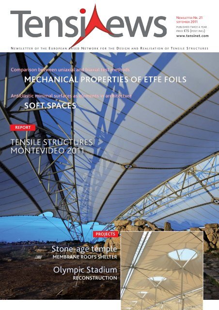
Comparison between uniaxial and biaxial test methods<br />
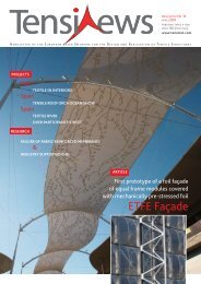
MECHANICAL PROPERTIES OF ETFE FOILS<br />
Anticlastic minimal surfaces as elements in architecture<br />
SOFT.SPACES<br />
REPORT<br />
TENSILE STRUCTURES<br />
MONTEVIDEO 2011<br />
PROJECTS<br />
Stone-age temple<br />
MEMBRANE ROOFS SHELTER<br />
Olympic Stadium<br />
RECONSTRUCTION<br />
NEWSLETTER NR. <strong>21</strong><br />
SEPTEMBER 2011<br />
PUBLISHED TWICE A YEAR<br />
PRICE €15 (POST INCL)<br />
www.tensinet.com
form TL<br />
partners<br />
2011<br />
Buro Happold<br />
www.burohappold.com<br />
Canobbio S.p.A.<br />
www.canobbio.com<br />
Ceno Tec<br />
www.ceno-tec.de<br />
Dyneon<br />
www.dyneon.com<br />
FabricArt<br />
Membrane Structures<br />
www.fabricart.com.tr/<br />
Ferrari sa<br />
www.ferrari-textiles.com<br />
Form TL<br />
www.Form-tl.de<br />
Hightex GmbH<br />
www.hightexworld.com<br />
Mehler Texnologies<br />
www.mehlertexnologies.com<br />
Messe Frankfurt<br />
Techtextil<br />
www.techtextil.de<br />
Naizil S.P.A.<br />
www.naizil.com<br />
Saint-Gobain<br />
www.sheerfill.com<br />
Sioen Industries<br />
www.sioen.com<br />
Taiyo Europe<br />
www.taiyo-europe.com<br />
technet GmbH<br />
www.technet-gmbh.com<br />
Verseidag<br />
www.vsindutex.de<br />
INFO<br />
Editorial Board<br />
John Chilton, Evi Corne,<br />
Peter Gosling, Marijke Mollaert,<br />
Javier Tejera<br />
Coordination<br />
Marijke Mollaert,<br />
phone: +32 2 629 28 45,<br />
marijke.mollaert@vub.ac.be<br />
Address<br />
Vrije Uni ver siteit Brussel (VUB),<br />
Dept. of Architectural Engineering,<br />
Pleinlaan 2, 1050 Brus sels, Belgium<br />
fax: +32 2 629 28 41<br />
ISSN 1784-5688<br />
All copyrights remain by each<br />
author<br />
Price €15<br />
postage & packing included<br />
2 TENSINEWS NR. <strong>21</strong> – SEPTEMBER 2011<br />
PROJECTS<br />
RESEARCH<br />
MISC<br />
contents<br />
PAGE<br />
4 France OPEN-AIR THEATER<br />
1800m² suspended structure<br />
4 Germany TEMPORARY ROOF<br />
STRUCTURE<br />
9 Ukraine OLYMPIC STADIUM<br />
Reconstruction<br />
16 China HOME OF THE FUTURE<br />
A showcase for future living<br />
16 Argentina LA PLATA STADIUM<br />
High-light transmission membranes<br />
17 Germany MEMBRANE ROOF Rhein-Galerie<br />
18 Malta STONE-AGE TEMPLE<br />
Membrane roofs shelter<br />
23 Spain TEXTILE WRAP A sustainable construction<br />
PAGE<br />
6 Mechanical properties of ETFE foils<br />
10 SOFT.SPACES<br />
REPORT<br />
PAGE<br />
19 LITERATURE<br />
8 S(P)EEDKITS<br />
n°<strong>21</strong><br />
PAGE<br />
20 Tensile Structures Montevideo 2011<br />
24 INTERNATIONAL "TEXTILE STRUCTURE FOR<br />
NEW BUILDING 2011” COMPETITION FOR STUDENTS AT TECHTEXTIL
E dito<br />
<strong>Tensinews</strong> observes the current trend of expanding<br />
the use of technical membranes and foils in architectural<br />
projects. The variation in available materials is increasing,<br />
with respect to the appearance as well as the (structural)<br />
behaviour. The field of application is widening; more delicate,<br />
creative and intriguing projects are being built and more<br />
architects explore the possibilities of the technology of tensile<br />
surface structures, e.g. textile sustainable wraps, a large<br />
span stadium cover or a heritage shelter to protect an<br />
archaeological temple. A holistic approach is the way to<br />
go for these designs.<br />
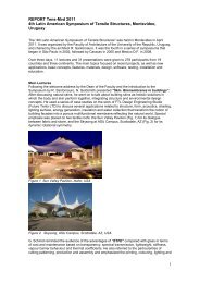
Numerous workshops, symposia - like the 4 th Latin American<br />
Symposium on Tensile Structures in Montevideo - and<br />
conferences act as forums to discuss and disseminate<br />
the state of the art. The next <strong>TensiNet</strong> Symposium is planned<br />
for 2013. The younger generation is stimulated to hand in<br />
their student-projects at the bi-annual International "Textile<br />
Structure for New Building 2011” Competition at Techtextil.<br />
There is also an increase in research projects to deepen the<br />
current knowledge, like testing and analysing the material<br />
properties of coated fabrics and foils, the study of deployable<br />
S(P)PEEDKITS for disaster relief or the exploration of<br />
anticlastic minimal surfaces as architectural and constructive<br />
components.<br />
A new <strong>TensiNet</strong> Working Group on Pneumatic Structures is<br />
launched: Matthew Birchall (matthew.birchall@ burohappold.<br />
com) will be the leader of this Working Group.<br />
The <strong>TensiNet</strong> association is part of the expanding topic of<br />
technical membranes and foils and hopes to further contribute<br />
to this evolution.<br />
Forthcoming Meetings<br />
<strong>TensiNet</strong> meetings in Barcelona, Spain<br />
Thursday 4/10/2011<br />
16:30 - 17:00 Welcome<br />
17:00 - 18:00 Partner Meeting (2/2011)<br />
18:00 - 19:00 Annual General Meeting<br />
19:00 - <strong>21</strong>:00 Working Group Meetings "Specifications" (Marijke Mollaert),<br />
"Analysis & Materials" (Ben Bridgens) and "ETFE" (Rogier Houtman)<br />
Location: Technical Uni<strong>vers</strong>ity of Catalonia (UPC),<br />
Master Room, Building A3, Campus Nord, Jordi Girona 1-3, Barcelona, Spain<br />
Forthcoming Events International symposium IABSE-IASS 2011 London,<br />
UK 20-23/09/2011 ● International conference on Structural Membranes 2011<br />
Barcelona, Spain 05-07/10/2011 http://congress.cimne.com/membranes2011/frontal/<br />
Dates.asp ● 1st international Textile Archi tecture Seminar Uni<strong>vers</strong>idad de Castilla-<br />
La Mancha,Toledo, Spain 26-28/10/2011 ● second international conference on flexible<br />
formwork icff 2012 Bath, UK 27 - 29/06/2012 www.icff2012.co.uk<br />
CALL<br />
for Participants for<br />
<strong>TensiNet</strong> Working Group on<br />
Pneumatic Structures<br />
Pneumatic Structures are increasingly being considered for a variety of<br />
applications in the built environment, from stadium roofs to bridges, and<br />
from permanent structures to deployable enclosures. The design, analysis<br />
and specification of these structures is often treated differently by<br />
different consultants in different countries, with occasional reliance upon<br />
qualitative and empirical experience, or applications from other industries.<br />
<strong>TensiNet</strong> is launching a working group on Pneumatic Structures to<br />
consolidate the current best practise in this specialist field. It is envisaged<br />
that this working group will focus on analysis techniques, design<br />
processes, applicable standards and technical references, materiality<br />
options, and construction practicalities. Reference will be made to the<br />
existing working groups on ETFE and Analysis & Materials without<br />
duplicating their findings, of course.<br />
The aims, scope and membership of the working group will be discussed<br />
at the start-up meeting to follow after the Annual General Meeting of<br />
<strong>TensiNet</strong> in Barcelona on 4 th October 2011. Any interested parties who<br />
would like to participate should contact the leader of the working group,<br />
Matthew Birchall, at matthew.birchall@burohappold.com<br />
CEN/TC250 WG5 _<br />
core group meeting<br />
in Paris, France<br />
Wednesday 02/11/2011<br />
10:00 - 16:00<br />
Core Group Meeting<br />
Location:<br />
SFEC, 3rd floor, 65 Rue Prony,<br />
Paris, France<br />
TENSINEWS NR. <strong>21</strong> – SEPTEMBER 2011 3
Context<br />
The City of Colmar wanted to<br />
cover the open-air theater of its<br />
Exhibition Park in a lasting and<br />
esthetic way. The challenge was<br />
to cover the existing Eastern and<br />
Western tiers by installing a<br />
textile cover fixed on a metal<br />
framework with particularly short<br />
delays and taking into account the<br />
existing equipment<br />
Context<br />
Built in early 19th century the<br />
“Festung Ehrenbreitstein” is a<br />
landmark in Koblenz, located<br />
opposite of the famous “Deutschen<br />
Eck” between Rhein and Mosel. In<br />
one of the moats of the historical<br />
“Festung Ehrenbreitstein” a main<br />
stage and stands for the<br />
Bundesgartenschau 2011 (BUGA<br />
2011) have been located (Fig. 1).<br />
All kind of concerts will take place<br />
from April until October 2011. The<br />
moat called “Retiriergraben” is<br />
about 24m to 27m wide and 100m<br />
long. The slope of the “Graben”<br />
ends in east direction at the<br />
“Landbastion”, is bordered to the<br />
North by “Kurtine” (both 25m high<br />
ancient walls) and to the South by a<br />
ramp in front of “Contregarde<br />
Rechts”, which is opposite inclined<br />
to the “Retiriergraben”, from 4 to<br />
12m height (Fig. 2). The moat opens<br />
up upwards.<br />
Client and investor was BUGA 2011,<br />
the owner is "Bundesland<br />
Rheinland-Pfalz“.<br />
4 TENSINEWS NR. <strong>21</strong> – SEPTEMBER 2011<br />
and the constraints inherent to<br />
the site. For example, the theater<br />
is located very close to the Colmar<br />
airport and part of the<br />
construction stands inside the<br />
area concerned by the planes’<br />
taking-off and landing operations.<br />
The solution chosen by ESMERY<br />
CARON was to install very big<br />
textile cones suspended at 20m<br />
above the theater stands.<br />
KIEFER TEXTILE ARCHITEKTUR<br />
Project<br />
Kiefer. Textile Architektur provided a<br />
range of architectural solutions,<br />
until the client´s and owner´s<br />
requirements, which changed<br />
Structure and installation<br />
The plan dimensions of the two<br />
covering modules are about 55m by<br />
2 X 65m, i.e. 2 textile co<strong>vers</strong> of<br />
900m² and 2.2 tons each. The metal<br />
structure supporting the tension fabric<br />
cover is mainly made of two triple<br />
masts of 3.5 tons each, holding<br />
a 135m long cable placed at an alti-<br />
ESMERY CARON<br />
Open-air<br />
theater<br />
1 Colmar, France<br />
1800M² SUSPENDED STRUCTURE<br />
during the design process, had been<br />
achieved. The final brief was to<br />
create a temporary covering for a<br />
stage of 8 to12m and<br />
approximately 800 spectators in a<br />
tude of about 20m. The textile co<strong>vers</strong><br />
are completely independent<br />
from the existing open-air theatre<br />
structures by being tensioned on<br />
main cables (56mm in diameter).<br />
The metal frames were treated by<br />
bath galvanization and bolted onsite.<br />
Erection of the elements was<br />
performed using a telescopic crane<br />
Temporary roof structure<br />
Festung Ehrenbreitstein, Germany<br />
Figure 1. Aerial view on the main stage © PP Koblenz<br />
way that no attention is taken away<br />
from the ancient masonry of the<br />
surrounding buildings and the new<br />
construction is not attached to the<br />
old (Fig. 3).<br />
1
installed close to the building site.<br />
The fabric was made in the workshop<br />
and folded in a specific order<br />
allowing a very precise on-site installation<br />
taking into account the<br />
need for working at heights and the<br />
dimensions of the construction. The<br />
fittings and various cables are made<br />
of galvanized steel with a metal<br />
core. Endings are of the rigid fork or<br />
threaded end types.<br />
The obvious solution was to build a<br />
roof<br />
• remarkable higher than the ramp,<br />
to invite looking from the ramp<br />
into the stage;<br />
• horizontally, in order to accentuate<br />
the falling and ascending lines<br />
along the ramp wall;<br />
• with respectful space between<br />
masonry and roof edge;<br />
• light and stringent seemingly,<br />
symmetrical main structure;<br />
• translucent and smooth shaped<br />
elements.<br />
Six portal frames in a grid of 7m,<br />
designed by three girder trusses,<br />
achieve minimum truss diameters.<br />
The horizontal upper girder<br />
cantile<strong>vers</strong> at both ends, in order to<br />
base aside of existing foundations.<br />
Excavations for the new precast<br />
concrete units had to be limited to<br />
max. 50cm. The vertical trusses vary<br />
from 11 to 15m height. Their lowest<br />
part is the adjusting element. The<br />
stiffing of the structure in<br />
longitudinal direction is induced by<br />
vertical cross bracing of each bay, in<br />
cross direction by portal frames. The<br />
fabric co<strong>vers</strong> six bays of 7x 22m.<br />
Each bay gets an accentuated shape<br />
through two valley belts, which<br />
divide the bay into three elongated<br />
areas. The middle one shows a<br />
classical slightly barrel-shaped form.<br />
It effects a reduction of the visual<br />
2 2 3 3 3<br />
Figure 1. Overview<br />
Figure 2. External and internal view of the<br />
two covering modules<br />
Figure 3. Installation<br />
! Olivier Dufour<br />
: olivier.dufour@esmerycaron.com<br />
: www.esmery-caron.com<br />
presence of the upper girder. To<br />
reduce any imperfections in the<br />
fabric there is no assembling along<br />
the top girder but two welded keder<br />
strips to hinder horizontal<br />
movement. At both end frames the<br />
fabric is clamped by standardized<br />
keder-clamping profile from Tennect<br />
to allow for unpunched linear<br />
fixation. Membrane edges are<br />
framed with belts to underline the<br />
temporary character.<br />
The valley belts are slightly curved<br />
to increase the dynamic appearance<br />
of the single bays. The belts are fixed<br />
to a rotatable supported bail<br />
consisting out of steel tubes. These<br />
bails are used to tension the<br />
membrane. Due to the various angle<br />
at the fixation points of tie down<br />
tension struts a standardized readymade<br />
product from Tennect was<br />
used. The roofing structure was<br />
finally completed one day before<br />
opening ceremony at 15th of April.<br />
The complete design, engineering<br />
and cutting pattern was carried out<br />
from Michael Kiefer, Tobias Lüdeke<br />
and Manfred Schieber at Kiefer.<br />
Textile Architektur.<br />
! Michael Kiefer<br />
Kiefer. Textile Architektur.<br />
Architekten und Ingenieure<br />
: info@k-ta.de<br />
: www.k-ta.de<br />
Project Name: Covering of the open-air theater, Exhibition Park<br />
Location address: Colmar, France<br />
Function of the building: Outdoor facilities<br />
Client: Colmar City<br />
Year of construction: July 2009<br />
Project Manager: Colmar City Architecture Department<br />
Metal framework: ACML<br />
Supplier of the membrane material: FERRARI 1502 T2 1500g/m² - EN ISO 2286-2 standard<br />
Membrane and framework Consultant: ARCORA<br />
Supplier of the membrane: ESMERY CARON<br />
Installation of the membrane: ESMERY CARON and EVEREST (3 weeks for a fitting team of 7)<br />
Covered surface: 1800m²<br />
Figure 2. View from the ramp to the main stage<br />
Figure 3. View main stage © Kiefer.Textile Architektur.<br />
2 3<br />
3<br />
Name of the project: Temporary roof structure<br />
Location address: Festung Ehrenbreitstein, Germany<br />
Client (investor): BUGA 2011 and Rheinland-Pfalz<br />
Function of building: Temporary roof of main stage and stand<br />
Type of application of the membrane: Valleycable Saddleshaped<br />
Year of construction: 2011<br />
Architects: Michael Kiefer, Sebastian Fey Kiefer.Textile Architektur.<br />
Structural engineers: Tobias Lüdeke, Manfred Schieber Kiefer.Textile Architektur.<br />
Consulting engineer for the membrane: Tobias Lüdeke Kiefer.Textile Architektur.<br />
Main contractor & contractor for the membrane: Ceno-Tec<br />
Supplier of the membrane material: Verseidag<br />
Manufacture and installation: Ceno-Tec<br />
Material: Verseidag B1951, PVC/ PES Typ 1<br />
Covered surface (roofed area): ca. 800m²<br />
Membrane assembling system: Tennect (Carl Stahl)<br />
TENSINEWS NR. <strong>21</strong> – SEPTEMBER 2011 5<br />
3
RESEARCH<br />
6 TENSINEWS NR. <strong>21</strong> – SEPTEMBER 2011
Preliminary definitions<br />
The mechanical behaviour of materials is<br />
described by relationships between stresses<br />
and strains. There exist however different<br />
definitions, the most commonly used being<br />
the engineering stress s and the engineering<br />
strain e. They are actually simplified<br />
formulations and are only valid under<br />
infinitesimal strains as they always refer to the<br />
material initial configuration. If the strains<br />
exceed a few percents then the true stress σ<br />
and true strain ε must be used. They represent<br />
the true material behaviour which is used in<br />
finite element analyses. The true stress<br />
accounts for change in cross-sectional area by<br />
using the instantaneous sample area. The true<br />
strain accounts for an incremental sample<br />
deformation where the new strain depends on<br />
the updated shape. The comparison between<br />
both definitions is illustrated in the part (B1) of<br />
the summary picture for the uniaxial tension<br />
of an ETFE foil. The engineering stress and<br />
strain are accurate enough in the initial linear<br />
part. Above 2% of strain the difference with<br />
the true stress and strain becomes significant.<br />
Test procedures<br />
Mechanical properties of ETFE foils<br />
Comparison between uniaxial and biaxial test methods<br />
ETFE foils have increasingly been used since the 1980's for roofs and claddings [1-4]. Their excellent<br />
light transmission capability combined with their lightness and flexibility has broadened the scope of<br />
large transparent structures. The low weight properties of ETFE foils allow the design of structures<br />
which would have been impossible to build with conventional materials such as glass.<br />
ETFE is a polymer and therefore it exhibits non-linear stress-strain behaviour as well as rate- and<br />
temperature-dependency [5]. Usually its behaviour is derived from uniaxial tensile tests [3-5].<br />
In that case the behaviour is often measured in both machine (extrusion direction) and trans<strong>vers</strong>e<br />
direction. There is also an increasing interest for biaxial tests because they allow the observation of<br />
the material response under biaxial stresses as occurring in a tensile structure. In particular bursting<br />
tests have become popular during the last years [6] as they enable very large biaxial deformations.<br />
However, the benefits of biaxial testing over uniaxial testing have not been clearly demonstrated so<br />
far for ETFE foils. Three tests methods are here compared [7]: uniaxial tension, biaxial extension of<br />
cruciform specimen and bursting test. The study is focused on the deter mination of the material<br />
mechanical properties from the experimental data. After an adequate post-processing these data<br />
are compared and the advantages of each test method are discussed.<br />
• Uniaxial tension<br />
Specimen shape: standard dumbbell<br />
Control: tra<strong>vers</strong>e displacement<br />
(A1) The tensile load is measured with a load<br />
cell while an optical extensometer measures<br />
the distance between two targets, allowing<br />
the calculation of the engineering stress and<br />
strain. The obtained stress-strain curve shows<br />
the non-linear behaviour of ETFE foils. After an<br />
initial linear part, it exhibit two points where<br />
the stiffness significantly decreases denoted as<br />
two yield points. The material undergoes very<br />
large deformations up to more than 400% at<br />
failure. One can also mention that the<br />
behaviour in the machine and trans<strong>vers</strong>e<br />
direction is very similar.<br />
(B1) The tensile true stress and strain can be<br />
calculated from the engineering stress and<br />
strain. The Poisson's ratio ν is required. It is<br />
however not obtained from the uniaxial test,<br />
unless a strain measurement is operated in the<br />
direction orthogonal to the loading. One can<br />
either assume an incompressible material<br />
behaviour (ν=0.5) or use a typical value for<br />
ETFE (ν=0.43 [7]). With this definition of stress<br />
and strain the increase of stiffness in the<br />
second half of the curve is even more<br />
pronounced. It is due to the reorganization in<br />
the polymer structure, where the molecular<br />
chains are reoriented in the loading direction.<br />
As a result the material is no longer isotropic.<br />
• Biaxial extension of cruciform specimens<br />
Specimen shape: cruciform<br />
Control: load on each grip<br />
(A2) The load is measured for each grip with a<br />
load cell and two needle extensometers<br />
measure the strain in the central area of the<br />
sample. It can be seen from the results that<br />
the failure occurs at small strains, which is due<br />
to the particular geometry of the sample. This<br />
early failure of the specimen at about 7% of<br />
strain is the main disadvantage of this method<br />
as it is not representative of the strains that<br />
the foil undergoes under large biaxial stresses.<br />
Biaxial machines however allow the<br />
application of different load ratios on the<br />
sample contrary to the bursting test.<br />
(B2) The biaxial true stress and true strain can<br />
be calculated from the engineering stress and<br />
strain. In that case the Poisson's ratio can be<br />
obtained from the biaxial tests if at least two<br />
load ratios are explored.<br />
• Bursting test<br />
Specimen shape: circular<br />
Control: air pressure during the inflation<br />
(A3) The material behaviour is observed at the<br />
pole where a 1:1 load ratio is obtained. The<br />
biaxial true strains at the pole are directly<br />
measured by a 3D optical system using digital<br />
image correlation. The air pressure is measured<br />
by a pressure sensor. Without post-processing<br />
no data is obtained as there is no mean of<br />
measuring the stress in the material.<br />
(B3) The true stresses at the pole are<br />
calculated based on pressure vessel theory.<br />
The bubble radius is estimated from the<br />
bubble shape measured with the 3D optical<br />
system using a surface fitting. The foil<br />
thickness at the pole is estimated using the<br />
initial thickness and the measured in-plane<br />
strains assuming that the material is<br />
incompressible (constant material volume).<br />
With the bursting test much higher biaxial<br />
strains are reached. In that case failure occurs<br />
at about 75% of engineering strain (true strain<br />
of 0.56). Therefore the bursting test must be<br />
used in order to observe the behaviour of the<br />
material and its failure under large biaxial<br />
stresses.<br />
Comparison<br />
It is not possible to directly compare the<br />
stress-strain curves that have been previously<br />
presented. Each of these curves represents the<br />
relationship between only one stress component<br />
and one strain component. In reality, the<br />
material behaviour is defined by a relationship<br />
between the stress tensor and the strain tensor.<br />
If one assumes a plane stress state without<br />
shear then for an isotropic material it is<br />
described by 3 equations:<br />
ε x = 1 σ x − ν σ y<br />
E E<br />
ε y = − ν σ x + 1 σ y<br />
E E<br />
ε z = − ν (σ x + σ y )<br />
E<br />
RESEARCH<br />
Under biaxial loading the strain in one direction<br />
is not only related to the stress applied in that<br />
direction but also to the stress applied in the<br />
TENSINEWS NR. <strong>21</strong> – SEPTEMBER 2011 7
orthogo nal direction due to the Poisson's effect.<br />
As far as multidirectional stresses are concerned,<br />
the Von Mises formulas can be used to combine<br />
the stresses and strains into an equivalent stress<br />
and an equivalent strain. The corresponding<br />
curves are presented in the summary figure (C)<br />
for two uniaxial tests, two biaxial tests and one<br />
bursting test performed at room temperature at<br />
almost identical strain-rates. Results are very<br />
similar up to the second yield stress. Above the<br />
second yield stress the large deformations<br />
occurring in the material change its<br />
microstructure and therefore its mechanical<br />
properties. The material becomes anisotropic and<br />
its behaviour depends on the applied loading.<br />
Conclusion<br />
It has been shown that if an adequate post-processing<br />
is used then similar stress-strain curves<br />
are obtained up to the second yield stress with<br />
uniaxial and biaxial test procedures. Therefore<br />
uniaxial test can be used for measuring the material<br />
initial behaviour as they are very easy to perform<br />
and do not require much material and time.<br />
If the plastic behaviour or the failure of the material<br />
must be investigated then biaxial stresses<br />
must be applied. In that case the bursting test is<br />
the most suitable method as it allows very large<br />
biaxial deformations. This method is however limited<br />
to a single load ratio (1:1 for a circular sample).<br />
In order to apply different load ratios a<br />
biaxial test machine can be used.<br />
! Cédric Galliot<br />
: cedric.galliot@empa.ch<br />
! Rolf Luchsinger<br />
: rolf.luchsinger@empa.ch<br />
Center for Synergetic Structures<br />
: www.empa.ch/css<br />
REFERENCES<br />
[1] K. Moritz. Bauweisen der ETFE-Foliensysteme.<br />
Stahlbau 2007;76(5):336-342.<br />
[2] S. Robinson-Gayle, M. Kolokotroni, A. Cripps, S.<br />
Tanno. ETFE foil cushions in roofs and atria.<br />
Construction and Building Materials 2001;15:323-327.<br />
[3] Y. Xiang, J. Li. Calculation and design of ETFE<br />
membrane structures. In: Proceedings of the IASS<br />
Symposium, Beijing, 2006.<br />
[4] M. Wu, J. Lu. Experimental studies on ETFE cushion<br />
model. In: Proceedings of the IASS Symposium,<br />
Mexico, 2008.<br />
[5] K. Moritz. Time-Temperature-Shift (TTS) of ETFE-foils.<br />
In: Kröplin B, Oñate E, editors. International<br />
Conference on Textile Composites and Inflatable<br />
Structures, Structural Membranes 2009. CIMNE:<br />
Barcelona, 2009.<br />
[6] L. Schiemann, S. Hinz, M. Stephani. Tests of ETFE-foils<br />
under biaxial stresses. In: Kröplin B, Oñate E, editors.<br />
International Conference on Textile Com posites and<br />
Inflatable Structures, Structural Membranes 2009.<br />
CIMNE: Barcelona, 2009.<br />
[7] C. Galliot, R.H. Luchsinger. Uniaxial and biaxial<br />
mechanical properties of ETFE foils. Polymer Testing<br />
2011;30(4):356-365.<br />
8 TENSINEWS NR. <strong>21</strong> – SEPTEMBER 2011<br />
RESEARCH<br />
S(P)EEDKITS<br />
Rapid deployable kits as<br />
seeds for self-recovery<br />
The project ‘S(P)EEDKITS’ , which will start in 2012, will research rapid<br />
deployable kits as seeds for self-recovery in disaster affected sites. A multidisciplinary<br />
team, consisting of different organizations throughout Europe, will develop a new<br />
emergency system of modular rapid deployable shelters, facilities and medical care.<br />
The kits must be transportable, modular and adaptable, must have a low cost and<br />
must be high-tech in their conception but low-tech in use (Fig. 1 gives an example of a<br />
feasible kit. However the implementation of the kit, in the context of disaster relief<br />
shelters, still needs to be investigated). Current kits will be scanned with regard to<br />
large transportation volumes and/or heavy weight. Out of this knowledge, new<br />
concepts will be developed to drastically reduce the transportation volume and weight.<br />
The goal of these kits will be to provide temporary infrastructure, to establish the<br />
necessary temporary services and to limit the damage to economic and social fabrics.<br />
The kits should provide infrastructure for different purposes, e.g. a hospital,<br />
a communication centre, water facilities or sanitation units. Also four different basic<br />
shelter kits will be designed and analyzed:<br />
- A lightweight safe house unit: this shelter gives coverage for the very first<br />
hours and need to be deployed by the communities<br />
- A collective unit: a shelter which is usable for di<strong>vers</strong>e purposes<br />
- A family house unit: this shelter will be used in the transitional period and<br />
later, it can be referred to as the first <strong>vers</strong>ion of a real house<br />
- A robust warehouse unit: a somewhat larger shelter for the humani-ta rian<br />
organizations, it can be used for storage, offices, medical centers, etc.<br />
The need for these kits becomes evident when thinking about the many disasters,<br />
both nature- and man-made, that occur worldwide. As a result, countless people are<br />
rendered homeless without any medical care, sufficient and clean water, decent<br />
sanitation or energy supply. In case of such an emergency situation, humanitarian<br />
organizations (like the Red Cross, Red Crescent Movement and Médecins Sans<br />
Frontières) emergency response units to rebuild these affected sites. These units are<br />
sent out immediately after a disaster strikes. Each unit has his own field of expertise<br />
and consists of trained people and the necessary equipment (the ‘kit’) needed on site.<br />
The S(P)EEDKITS project wants to develop novel ‘kits’ that can be pre-positioned and<br />
mobilized more quickly and easily than existing ones.<br />
The S(P)EEDKITS project will be a collaboration between : Centexbel (BE),<br />
Shelter Research Unit (LU), Netherlands Red Cross (NL), Sioen Industries (BE),<br />
Vrije Uni<strong>vers</strong>iteit Brussel (BE), Technische Uni<strong>vers</strong>iteit Eindhoven (NL),<br />
Politecnico di Milano (IT), De Mobiele Fabriek (NL), Waste (NL), Practica (NL),<br />
D’Appolonia (IT), Internationales Biogas und Bioenergie Kompetenzzentrum (DE),<br />
Millson BV (NL), MSF Nederland (NL) and Norwegian Refugee Council (NO).<br />
! Jan Roekens - Vrije Uni<strong>vers</strong>iteit Brussel<br />
: jan.roekens@vub.ac.be<br />
! Guy Buyle - Centexbel<br />
: guy.buyle@centexbel.be<br />
Figure 1: First<br />
steps in the<br />
design of a<br />
possible disaster<br />
relief shelter kit
Introduction<br />
Over the last decades Hightex has<br />
been dedicated to the construction<br />
of innovative fabric roofs for<br />
sporting venues. One of the stadium<br />
projects for the EURO 2012 in the<br />
Ukraine and Poland is the Olympic<br />
Stadium in Kiev, which is currently<br />
undergoing a comprehensive<br />
revitalization. The design for the<br />
reconstruction of the stadium<br />
respects the historical building with<br />
its significant filigree prestress<br />
concrete upper tier tribunes from<br />
1968, by arranging the<br />
superstructure of the new roof<br />
system detached and with a<br />
distance to the existing seating<br />
bowl. The most prominent part of<br />
the “Kiev Central Stadium” will be<br />
enclosed with a new delicate glazing<br />
façade and, like an exhibit in a glass<br />
cabinet, will be put in perspective<br />
with lighting. This is how the<br />
architect von Gerkan, Mark and<br />
Partner (gmp) describe their design.<br />
With its fabric roofing system<br />
shaped by filigree flying struts into<br />
an ocean of conicals covered with<br />
light domes the Olympic Stadium<br />
should receive a unique and<br />
distinctive identity as an urban<br />
landmark within the texture of the<br />
city centre of Kiev. The main<br />
structural system of the roof derives<br />
from the spoke wheel principal. It<br />
consists of two outer compression<br />
rings, steel plate box girders, which<br />
rest on the 80 kinked columns, also<br />
made of tapered steel box girders.<br />
80 cable trusses of upper and lower<br />
radial cables, coupled with hanger<br />
cables build up a light cable net,<br />
which are anchored into these<br />
compression rings and meet at the<br />
centre in a tension ring. The tension<br />
ring encases approximately the<br />
playing pitch. The horizontal forces<br />
are balanced out between the outer<br />
compression rings and the inner<br />
tension ring. The vertical forces are<br />
HIGHTEX GMBH<br />
RECONSTRUCTION<br />
Olympic Stadium<br />
Kiev, Ukraine<br />
transferred from the cable net into<br />
the 80 columns and into the<br />
foundations. 80 axes are very<br />
uncommon for stadium roof<br />
constructions. Similar projects<br />
usually make do with about half the<br />
number of axes.<br />
One of the reasons for this design<br />
was the original material choice of<br />
the main membrane. First concepts<br />
envisioned the use of a single layer<br />
of ETFE foil. It has much lower<br />
structural capacity than typical<br />
coated fabrics, which are usually<br />
used for stadium roofs. While the<br />
fabrication and installation of the<br />
steel columns was already under<br />
way, the material choice of the<br />
highly transparent foil was<br />
dismissed over the course of the<br />
planning. The 80 columns still<br />
dominate the overall impression of<br />
the architecture of the stadium and<br />
will impress a unique character<br />
onto the stadium. The roof cover,<br />
the translucent membrane field<br />
elements, will now be made of<br />
PTFE coated Glass fabric. Eight<br />
flying struts in each bay impress a<br />
series of conical shapes into the<br />
main membrane. These flying struts<br />
flare up like a funnel and the main<br />
membrane is connected to the top<br />
rings of the flying struts. The round<br />
openings between 2.5m to 3.2m<br />
diameter are covered with light<br />
domes spanned with ETFE foil. This<br />
generates a unique translucent<br />
roofing landscape with in total 640<br />
light spots. For this project Hightex<br />
is responsible for the cable<br />
structure and membrane roof.<br />
Cable structure (Fig. 1 to Fig. 5)<br />
The ten ring cables are 115mm<br />
diameter also fully locked galvan<br />
cables and have a total length of<br />
about 469m each. They are bundle<br />
into two layers of 5 cables each and<br />
Installation of the cable structure<br />
Figure 1. Connection of upper radial cable and<br />
ring cable<br />
Figure 2. Layout of ring cable<br />
connected to the so called ring<br />
cable connectors. These are 2.5t<br />
castings, which have two vertically<br />
arranged cleats, connect the upper<br />
and lower radial cables to the ring<br />
cables. The upper and lower radial<br />
cable, also fully locked galvan<br />
cables are interconnected with<br />
8 hanger cables each build up the<br />
80 cable trusses. The cables are<br />
fabricated with fork terminals at<br />
each end. One end connects to the<br />
ring cable connector and the other<br />
end connects to cleats at the upper<br />
and lower compression rings.<br />
1 3 5<br />
2<br />
Figure 3. Lifting of spreader bar<br />
Figure 4. Cable net roof construction<br />
Figure 5. Pinning of fork terminal<br />
TENSINEWS NR. <strong>21</strong> – SEPTEMBER 2011 9<br />
4
For the installation the radial<br />
cables and ring cables are laid out<br />
in the stadium bowl. The open ends<br />
of the radial cables are fitted with<br />
temporary spreader bars to take on<br />
the lifting equipment. The upper<br />
radial cables are pulled towards the<br />
upper compression ring with strand<br />
jacks and pinned. This process will<br />
lift the cable net completely off<br />
the ground. Then the last 1.5m of<br />
the lower radial cables are pulled<br />
with the threaded bars and hollow<br />
hydraulic cylinders towards the<br />
lower compression ring until all<br />
cables can be pinned. This process<br />
is called the “big lift” and takes<br />
about 30 days.<br />
Membrane structure<br />
(Fig. 6 to Fig. 11)<br />
For the next installation step the<br />
membrane roof panels are fitted<br />
onto the completely stressed cable<br />
net. Each of the 80 bays consists of<br />
about 600m² PTFE/Glass mem -<br />
brane panels with an approximate<br />
weight of one tone. The membrane<br />
Installation of the membrane<br />
Figure 6. Beginning of membrane installation<br />
Figure 7. Roof view from below<br />
Figure 8. High point installation<br />
10 TENSINEWS NR. <strong>21</strong> – SEPTEMBER 2011<br />
fields will be cut from the virgin roll<br />
material, welded and assembled<br />
ready-to-install off site in the<br />
factory. They get packed, shipped to<br />
site and directly lifted onto the roof.<br />
The membranes are unfurled from<br />
the rolling rack on the lower<br />
compression ring. The membrane is<br />
then connected at the circular cut<br />
outs to the already positioned but<br />
lowered flying struts. The final<br />
shape and prestress is brought into<br />
the membrane by lifting the flying<br />
struts into their final position.<br />
This process is assisted by hydraulic<br />
jacks at the footing of the flying<br />
struts. The roof structure is<br />
completed after all the 640 light<br />
domes are mounted.<br />
! Gregor Grunwald<br />
: gregor.grunwald@<br />
hightexworld.com<br />
! Markus Seethaler<br />
markus.seethaler@<br />
hightexworld.com<br />
: www.hightexworld.com<br />
© Pictures: Hightex GmbH<br />
Name of the project: Olympic Stadium Kiev<br />
Location address: City of Kiev, Ukraine<br />
Client (investor): Olympic National Sports Complex, Ukraine<br />
Function of building: sport stadium<br />
Year of construction: 2010-11<br />
Architects: gmp • Architekten von Gerkan, Marg und Partner,<br />
Personal Creative Architectural Bureau Y. Serjogin<br />
Structural engineers: SBP – Schlaich Bergermann und Partner<br />
Manufacture and installation of cable net and membrane: Hightex GmbH<br />
Supplier of the membrane material: Verseidag-Indutex GmbH<br />
Material: PTFE-Glass<br />
Covered surface (roofed area): approx. 45.000m²<br />
6 7<br />
8<br />
10<br />
Figure 9. Roof top view<br />
Figure 10. Different stages of high point<br />
installation<br />
Figure 11. Installation of the high point<br />
clamping profile<br />
9<br />
11<br />
Anticlastic minimal<br />
surfaces as elements<br />
in architecture<br />
Introduction<br />
On the basis of the research of Frei Otto<br />
and his team at IL (Uni<strong>vers</strong>ity of Stuttgart)<br />
and the resulting exceptional pioneer<br />
constructions, building with textiles as an<br />
alternative to traditional materials like wood,<br />
stone, steel, glass, and concrete was<br />
rediscovered during the last decades.<br />
Deriving from self organizing forms of Minimal<br />
Surfaces, prestressed, spatially curved<br />
Membrane Structures were up to today<br />
mainly used for wide span, lightweightstructures.<br />
For this reason membrane<br />
structures tend to be seen from a<br />
structural or material point of view only.<br />
In contrast to our right-angled, conventionally<br />
built environment the desire for fluent<br />
“soft” spaces in architecture cannot be<br />
o<strong>vers</strong>een any more. The possibility to create<br />
light and fluent spaces as a symbiosis of<br />
form and structure offers new qualities<br />
and chances in the architectural design<br />
of residential or office buildings for example.<br />
Subject<br />
This article presents the overview of the<br />
research on spatially curved Minimal Surfaces<br />
that considers the infinite possibilities of<br />
membrane forms as elements in architecture<br />
in combination with common buildingtechnologies<br />
and shows new capabilities in<br />
designing and creating spaces. Seen as an<br />
element in the design of architecture these<br />
anticlastic, fluent forms caused by structural<br />
conditions, follow the rules of formfinding in<br />
its initially (by Frei Otto) defined sense.<br />
Very often we misuse the term „formfinding“.<br />
What Architects mostly mean and do is a man<br />
controlled process of shaping - a process that<br />
happens on a consciously controllable and<br />
formal level. In contrast to the mancontrolled<br />
process of shaping, forms that are<br />
arising from self organizing processes can only<br />
be influenced by the design of their<br />
boundaries. The form itself can only be found<br />
and represents the result which cannot be<br />
manipulated. The architect finds himself in the<br />
unusual position of a creative “formfinder”<br />
instead of the “shaper”.<br />
The fluent forms of Minimal-Surfaces are<br />
fascinating by their variety, structural<br />
performance, reduction to the minimal in<br />
terms of material use and resources and their<br />
special fashion-resistant aesthetics.
RESEARCH<br />
SOFT.SPACES<br />
Together these parameters represent the<br />
common basis of a potential design or design<br />
concept and characterize its grade of<br />
sustainability.<br />
Objectives<br />
Since self organizing processes follow precise<br />
rules and contain optimization by their<br />
nature descriptions and especially in<br />
architecture illustrations of these rules can be<br />
used as design tools [1] . To find out about the<br />
chances for an architecture between „hard“<br />
and „soft“ morphology, basic research on the<br />
systematic determination of very different<br />
boundaries - the interface between<br />
membranes and common construction<br />
technologies - enables the opportunity to<br />
analyze anticlastic Minimal Surfaces<br />
regarding form and curvature. Vice <strong>vers</strong>a we<br />
get an idea of the correlation between 3dcurvature,<br />
deflection and determined<br />
boundary and further on an idea of formal<br />
and structural behavior. In this context the<br />
assessment and visualization of the Gaussian<br />
curvature, which were adapted especially to<br />
this research, played an important role.<br />
Special Specifications<br />
1 Minimal surface<br />
All experiments are restricted to forms that<br />
can be derived from the results of soapfilm<br />
models – the Minimal Surface. As long as<br />
boundary conditions are not changed,<br />
Minimal Surfaces can be arranged as a unity<br />
arbitrarily in space without changing its<br />
form/geometry.<br />
2 Interface<br />
Linear, maximal 2dimmensionally curved,<br />
bending resistant, line supported boundaries<br />
Figure 1. Physical study model -<br />
showing catenoids between<br />
shifted circular rings<br />
Figure 2. Sequence of Soapfilm<br />
Models<br />
turned out to be the ideal interface between<br />
membranes and common construction<br />
technologies. All further experiments were<br />
restricted to boundaries of that kind.<br />
3 Membranes as an integrative<br />
element<br />
Membranes are seen as an integrative<br />
component of architecture and are directly<br />
connected to other elements of common<br />
construction methods. In terms of structural<br />
effectiveness the surfaces themselves are<br />
considered to be highly efficient by their<br />
spatial curvature but not to be load bearing<br />
elements for other structural members<br />
although newest approaches in the author`s<br />
research are dealing with this possibility.<br />
Investigations<br />
The range of exploration co<strong>vers</strong> wall-like<br />
elements, T-shaped connections, solutions<br />
for vertical, horizontal and free corners and<br />
the tubular entities of the Catenoid.<br />
Methods<br />
Besides physical (Fig. 1) and soapfilm models<br />
(Fig. 2) mainly digital experiments (Fig. 3)<br />
were used for the interpretation and the<br />
verification of results. Soapfilm models were<br />
mainly considered to fulfill a control<br />
function. Digital models were essential for<br />
the analysis and evaluation of forms (section<br />
curves, their diagrammatic overview, analysis<br />
of angles in space,…) of Minimal Surfaces. In<br />
this context the assessment and visualization<br />
of the Gaussian curvature (Fig. 4), which were<br />
adapted especially to this research, made it<br />
possible to compare and to draw one`s<br />
conclusions on different forms and their<br />
structural behavior.<br />
Figure 3. Digital model of a<br />
catenoid between circular rings<br />
and Visualization of Gaussian<br />
Curvature<br />
Figure 4. Special unification of<br />
assessment and visualization of<br />
the Gaussian curvature for this<br />
research<br />
Results of<br />
investigation<br />
The results of physical, soapfilm and mainly<br />
digital experiments show surprising and<br />
partly new correlations between form and<br />
boundary proportions and so far unknown<br />
rules of the self organizing processes of<br />
Minimal Surfaces – especially in the field of<br />
the Catenoid. The overview and the<br />
comparison of the results as well as the<br />
possibility of a targeted selection can<br />
therefore be the basis for creative<br />
applications.<br />
1 Minimal surfaces between<br />
straight lines and boundaries<br />
consisting of segments of a circle<br />
All experiments related to this series (Fig. 5)<br />
show, that for this boundary condition it is<br />
not possible to find a fully anticlastic curved<br />
Minimal Surface. Those surfaces which show<br />
few flat areas are generated within a<br />
relatively small spectrum of boundary<br />
conditions. They concentrate on boundary<br />
conditions consisting of semicircles with a<br />
diameter that corresponds to the distance of<br />
the boundaries. Independent of the<br />
amplitude of the curved boundary Minimal<br />
Surfaces tend to be flat in the near of the<br />
straight line boundary.<br />
Experiments show that in average up to 96%<br />
of the horizontal deflection that was given by<br />
the curved boundary is disappearing halfway<br />
between the upper and lower boundary.<br />
Horizontally shifted boundaries (Fig. 6) can<br />
be interesting from the architectural point of<br />
view. But in terms of anticlastic Gaussian<br />
Curvature this always means a further<br />
increase of flat areas.<br />
1 2 3 4 5<br />
6<br />
Figure 5. Minimal Surfaces<br />
between straight lines and<br />
boundaries consisting of<br />
segments of a circle<br />
Figure 6. Horizontally shifted<br />
boundaries<br />
TENSINEWS NR. <strong>21</strong> – SEPTEMBER 2011 11
RESEARCH<br />
2 Minimal surfaces between<br />
boundaries consisting of<br />
segments of a circle<br />
In this case the boundaries of wall like Minimal<br />
Surfaces can have the same direction or they<br />
can be arranged in<strong>vers</strong>ely. Horizontally shifted<br />
boundaries represent special cases and show<br />
interesting architectural effects. The horizontal<br />
offset can be in longitudinal, cross or diagonal<br />
direction.<br />
Minimal Surfaces between boundaries<br />
consisting of segments of a circle<br />
in the same direction<br />
Boundaries that are curved in the same<br />
direction (Fig. 7) generally effect strong<br />
anticlastic curvature of Minimal Surfaces.<br />
Boundary conditions consisting of semicircles<br />
with a diameter that equals the distance of the<br />
boundaries can be qualified as 100% spatially<br />
curved. Section lines show the smallest circle<br />
of curvature exactly on half height and<br />
harmonic development of the surfaces (Fig. 8).<br />
Minimal Surfaces between boundaries<br />
consisting of in<strong>vers</strong>ely arranged segments<br />
of a circle<br />
Curved and in<strong>vers</strong>ely arranged boundary<br />
conditions effect anticlastic curvature covering<br />
most of the surface, even if the boundaries have<br />
little oscillation from the longitudinal axis. The<br />
mostly curved surface can be developed with<br />
boundaries consis ting of semicircles with a<br />
diameter of 2/3 of the distance of the<br />
boundaries (Fig. 9). Areas with little spatial<br />
curvature can first of all be found exactly at the<br />
maxima of boundary curvature and on half<br />
height. Starting from the ideal case these flat<br />
areas increase with increasing as well as with<br />
decreasing diameters of the base-circles.<br />
Surfaces arising from boundary conditions with<br />
base-circles bigger than the height show<br />
12 TENSINEWS NR. <strong>21</strong> – SEPTEMBER 2011<br />
Figure 7. Boundary configurations consisting of<br />
segments of circles having the “same direction”<br />
Figure 8. Vertical section of digital models and<br />
their circles of curvature, all having their center<br />
at half height.<br />
Figure 9. EM KK 2/3 _ 1,00HK ggs<br />
Figure 10. EM KK 2/1 _ 0,50HK ggs<br />
Figure 11. EM KK 1/2 _ 1,00HK ggs<br />
Figure 12. Horizontal Corner<br />
Figure 13. Vertical Corner<br />
Figure 14. Free Corner 7 8<br />
9 10<br />
11<br />
flattened vertical stripes (Fig. 10) whereas<br />
flattened horizontal stripes (Fig. 11) appear with<br />
boundaries consisting of segments of circles<br />
with less than the height.<br />
3 Membranes corners<br />
Regarding corner solutions, boundaries can be<br />
arranged horizontally (Fig. 12) or vertically (Fig.<br />
13). The free corner (Fig. 14) describes a special<br />
case. The vertical and free membrane corner<br />
will not be described in this article..<br />
Horizontal membrane Corner<br />
All executed experiments with horizontal rightangled<br />
corners show almost constant surface<br />
curvature (Fig. 15) and deflection in the area of<br />
12 13 14<br />
15 16 17<br />
18 19<br />
the corner (Fig. 16). This happens<br />
independently form the leg length and from<br />
being arranged symmetrically or asym metri -<br />
cally. The section lines of digital models are<br />
congruent (Fig. 17). Leg length being shorter<br />
than the height cause surfaces with little<br />
anticlastic curvature. Surfaces of maximum<br />
spatial curvature in all areas can be achieved<br />
with a ratio 1/1 to 3/2 of leg length/height.<br />
Increased leg length causes areas with little<br />
anticlastic curvature at the end of the legs.<br />
4 T-connection<br />
Surfaces meeting in a T-connected boundary<br />
(Fig. 18) generate a Y-intersection (Fig. 19).<br />
Figure 15.<br />
Horizontal corner with<br />
ratio of 1 1 1<br />
(leg/leg/height)<br />
Figure 16.<br />
Horizontal corner with<br />
ratio of 111 Gaussian<br />
Curvature<br />
Figure 17.<br />
Horizontal section lines<br />
„Horizontal Membrane<br />
Corner“ – in comparison<br />
Figure 18.<br />
Geometry of right angled<br />
T-connection<br />
Figure 19.<br />
Minimal Surface generated<br />
from a right angled<br />
T-connection
Figure 20. Displacement of vertical section lines from right<br />
angled T-connection with symmetric wing length and<br />
different element length [EL]<br />
Figure <strong>21</strong>. T-connection with square boundary geometry<br />
FL = EL/2<br />
Figure 22. Linear increase of displacement at increasing<br />
element length up to EL/2=FL, then nonlinear<br />
Figure 23. T-connections different from 90°<br />
Figure 24. T-connection with an angle of 60°<br />
Figure 25. Vertical section lines T30°, T45°, T60°, T75°<br />
Figure 26. Spatially curved intersection line for T60°<br />
This happens independently from the angle<br />
of the boundary connection. The 3 different<br />
parts of the Minimal Surface meet with 120°<br />
and form an arch-like intersection. This arch<br />
is less curved at its angular point and more<br />
curved the closer it is to the T-connection of<br />
the boundary. „In very special cases only, a<br />
circular intersection can be formed .” [2]<br />
These special cases were used to form<br />
pressure resistant arches for real structures.<br />
Right-angled T-connection<br />
In terms of right-angled configurations the<br />
leg length of H (0) has no influence on the<br />
form of the generated Minimal Surface as<br />
long as it is longer than the deflection of the<br />
Y-intersection. This happens to be the same,<br />
independently from the wings being<br />
arranged symmetrically or asymmetrically.<br />
> Symmetric wing lenght [FL]: For symmetric<br />
wing length [FL] one can determine that the<br />
magnitude of the Y-intersection is directly<br />
connected to the ratio of wing length and<br />
element length. For all boundary conditions<br />
with FL ≥ EL/2 the magnitude of the<br />
Y-intersection equals 20,6% of the element<br />
length. For wing length shorter than the<br />
element length, a nonlinear behavior of the<br />
Y-intersection can be determined. So the<br />
boundary condition FL=EL/2 represents the<br />
borderline between linear and nonlinear<br />
development of displacement in the<br />
direction of H (Fig. 20). A square geometry in<br />
plan causes evenly distributed curvature in<br />
the surface (Fig. <strong>21</strong>).<br />
The curved Y-intersection is similar to a<br />
basket arch (Fig. 22). Starting from a square<br />
geometry in plan increased wing length<br />
results in the generation of insufficiently<br />
curved areas at the ends of the wings. On the<br />
other hand there are no effects on the form,<br />
radii of curvature of the Minimal Surface and<br />
the transitional zone with anticlastic<br />
curvature to insufficiently curved areas does<br />
not move. The enlargement of the element<br />
length which corresponds propor tionally to a<br />
reduction of the wing length causes<br />
insufficiently curved areas which are merged<br />
together in the element middle. Strong<br />
anticlastic curvature is limited to the areas of<br />
the T-connection of the boundary.<br />
> Asymmetric wing lenght [FL]: Spatially<br />
curved Y-intersections and spatially<br />
curvature of all partial areas are generated by<br />
asymmetric wing length. The horizontal<br />
component of the deflection always occurs<br />
in direction of the larger wing.<br />
Non-right-angled T-connections<br />
When using T-connected boundaries with<br />
angles different from 90° the surface of H<br />
(Fig. 23), which is totally flat for the 90° case,<br />
will be spatially curved too. Increasing<br />
deviation of 90° goes along with increasing<br />
anticlastic curvature of surface H (Fig. 24).<br />
The formally interesting Minimal Surfaces<br />
which develop as a result of a T-connection<br />
with a not at right angles deviating surface H<br />
show spatially curved intersection lines. The<br />
more the angle differs from 90° the more the<br />
anticlastic curvature of H increases. At the<br />
same time the vertical deflection of the<br />
former horizontal parts decreases.<br />
RESEARCH<br />
<strong>21</strong> 22<br />
23<br />
25 26<br />
5 Catenoid<br />
The shape of the catenoid is basically<br />
generated by a catenary that rotates around<br />
a longitudinal axis. It is the only rotational<br />
body that can be minimal surface at the<br />
same time. As we know from SFB230 the<br />
maximum attainable height of a catenoid<br />
spanning two circular rings is approximately<br />
1,3 times the radius of a ring. [3]<br />
For conceptual designs in architecture,<br />
boundaries different from two identical<br />
circles but with different diameters, not<br />
being arranged in one axis and/or not being<br />
symmetrically arranged are needed. So the<br />
maximum attainable heights of catenoids<br />
with different boundary geometries and<br />
arrangements were examined. New rules<br />
could be found for major boundary<br />
configurations [4] . The resulting diagrams can<br />
be scaled at will.<br />
Catanoids between circular rings<br />
of different diameters<br />
Starting from the extreme of 1,3 times the<br />
radius of a ring the maximum height of a<br />
20<br />
24<br />
TENSINEWS NR. <strong>21</strong> – SEPTEMBER 2011 13
RESEARCH<br />
catenoid is decreasing if one of the rings<br />
diameter is decreasing (Fig. 27).<br />
Fig. 27 also illustrates that upper rings<br />
smaller than 1/5 (upper ring /lower ring)<br />
effect very little maximum attainable<br />
height and surfaces with little Gaussian<br />
Curvature at the same time. Several<br />
experiments showed that all the<br />
attainable maxima in dependence from<br />
the given diameters are located on a<br />
common circle - the extreme value circle.<br />
This circle again is in direct proportion to<br />
the circular base ring (Fig. 28).<br />
The developed diagram allows a<br />
determination of the maximal attainable<br />
height when the diameters of the two<br />
rings are given. The other way round<br />
the maximal diameter of the upper ring<br />
can be found by predefining the desired<br />
height and the diameter of the base ring<br />
(Fig. 29).<br />
Case-Study A (Fig. 30)<br />
A catenoid is perforating several floors<br />
and creates a courtyard situation.<br />
Its position is chosen the way that the<br />
ground floor gets a spatial incision whilst the<br />
other floors are still connected by a catwalk<br />
between catenoid and facade.<br />
14 TENSINEWS NR. <strong>21</strong> – SEPTEMBER 2011<br />
28<br />
32<br />
35<br />
Case-Study G (Fig. <strong>31</strong>)<br />
The form of the catenoid is intersected with<br />
a rectangular building. In this case the<br />
catenoid was tilted in the direction from<br />
(left) and towards (right) the building. For<br />
this reason the opening in the façade opens<br />
on top and narrows to the sky inside the<br />
courtyard (left) and vice <strong>vers</strong>a (right).<br />
Catenoids between shifted circular<br />
rings<br />
A displacement of the boundary rings<br />
effects lower maximum heights of<br />
catenoids<br />
(Fig. 32).<br />
This correlation also follows precise rules.<br />
The interrelation of displacement of<br />
boundary rings and maximal attainable<br />
height of the catenoid can be found on<br />
circular movements defined by the center<br />
of the base ring and the diameter of the<br />
rings (Fig. 33).<br />
At the same time we can observe that a<br />
displacement of more than ¾ of the<br />
diameter of the rings effects areas with<br />
little Gaussian Curvature. Strongly curved<br />
areas can always be found at half height of<br />
the catenoid. A displacement of 1 diameter<br />
27<br />
29<br />
33<br />
36<br />
of the boundary rings cannot be attained<br />
with a catenoid but forms two separated<br />
surfaces within the rings.<br />
Case-Study K (Fig. 34)<br />
A horizontal displacement of one of the<br />
boundaries of the catenoid enables a spatial<br />
movement. For the fact that the base rings of<br />
displaced catenoids have equal diameter<br />
they can act like swivel plates. This way<br />
vertical connections or orientation to natural<br />
light can be solved.<br />
Catenoids between square rings<br />
of the same side lenght<br />
Compared to catenoids generated by two<br />
circular rings, catenoids between two equal<br />
square rings (Fig. 35) are having their<br />
maximum height at 1,44times of the side<br />
length of the square (Fig. 36). In analogy to<br />
catenoids between circular rings the maximal<br />
attainable height or the smallest possible<br />
upper square can be found on a common<br />
extreme value circle too.<br />
Catenoids between a square and<br />
a circular ring<br />
Catenoids between a square and a circular<br />
ring don`t follow an extreme value circle but<br />
30<br />
<strong>31</strong><br />
34<br />
37<br />
38
a catenarylike line starting from the center of<br />
the square and going through the quadrant<br />
of the upper circular boundary.<br />
The maximal attainable height equals<br />
1,39times the radius of the inscribed<br />
circle of the square respectively half of<br />
its side length. This is valid for configurations<br />
where the circle is the incircle at the<br />
most.<br />
Congruent cut-outs from<br />
Minimal Surfaces of Catenoids<br />
All executed investigations have shown<br />
that each randomly selected cut-out<br />
from a Minimal Surface of a catenoid<br />
will be a Minimal Surface with equal<br />
position in space and equal curvature of<br />
the surface itself. This can be explained<br />
by the absolute identical stresses in all<br />
directions of Minimal Surfaces.<br />
The example in Fig. 37 is showing a<br />
randomly selected closed curve that<br />
is projected on the surface of a catenoid.<br />
For this reason this curve is exactly<br />
matching the surface of the initial<br />
catenoid. By defining this curve as a<br />
new boundary line the new surface<br />
within this boundary is also matching<br />
the surface of the initial catenoid.<br />
40<br />
39<br />
Figure 27. Change of form and change of Gaussian<br />
Curvature of a Catenoid with decreasing<br />
diameter of upper ring and therefore decreasing<br />
height<br />
Figure 28. 3dimensional diagram for catenoids<br />
between circular rings of different diameters<br />
Figure 29. Soapfilm model and diagram for<br />
catenoids between circular rings of different<br />
diameters<br />
Figure 30. Case-Study A<br />
Figure <strong>31</strong>. Case-Study G<br />
Figure 32. 3d view of overlayed catenoids between<br />
shifted circular rings showing the circular<br />
movement of the upper ring and the<br />
dependence of horizontal displacement of the<br />
rings and the loss of height.<br />
Case-Study M2 (Fig. 38)<br />
The intersection of several catenoids is<br />
possible without changing of form of the<br />
different parts. This way 3dimensionally<br />
curved ridges are developed by the inter sec -<br />
tion line.The definition of the new boundary<br />
can be found as described before, but it can<br />
also be found by intersecting different<br />
independent catenoids or by intersection<br />
with other forms. As shown in case-study M2<br />
(Fig. 38) catenoids even don`t need to have<br />
the same position in space or the same size.<br />
This way a lot of possibilities are open for a<br />
potential design in architecture.<br />
Conclusion on research,<br />
case-studies and<br />
experimental structures<br />
The characteristics that Minimal Surfaces<br />
can be proportional scaled and that a<br />
predefined cut-out of minimal surface<br />
keeps unchanged multiplies the<br />
possibilities for the design. Using the found<br />
rules case studies give an idea of the<br />
infinite possibilities that are open to create<br />
very special „soft spaces”, with new<br />
architectural qualities like shown in above<br />
case studies and experimental structures<br />
(Fig. 39 to Fig.41) and furthermore.<br />
Figure 33. Side view of overlayed catenoids between<br />
shif ted circular rings showing the circular move -<br />
ment of the upper ring and the dependence of<br />
ho ri zontal displacement of the rings and the loss<br />
of heigh<br />
Figure 34. Case-study K<br />
Figure 35. 3dimensional diagram for catenoids<br />
between square rings of the same side length<br />
Figure 36. Diagram for catenoids between square<br />
rings of the same side length<br />
Figure 37. Congruent cut-outs from Minimal<br />
Surfaces of Catenoids<br />
Figure 38. Case Study M2<br />
Figure 39. “Cube of Clouds” experimental<br />
structure in model and in scale 1/1 by<br />
koge, Institute of Structure and Design,<br />
Perspective<br />
Latest approaches are dealing with alter na -<br />
tive boundary-conditions and with software<br />
implementation in terms of scripting found<br />
rules [5] (Fig. 42). The aspect of geometrical<br />
regularity a visual irregu larity of anticlastic<br />
Minimal Surfaces is subject of an actual re -<br />
sear ch project. An investigation on the<br />
cor re lation of self organizing forms, their<br />
close relation to nature and their aesthetic<br />
values also seems to be interesting questions<br />
for the future.<br />
! Günther H. FILZ<br />
: guenther.filz@uibk.ac.at<br />
© www.koge.at<br />
RESEARCH<br />
REFERENCES<br />
[1] Filz, Günther, “DAS WEICHE HAUS soft.spaces”,<br />
Dissertation, Leopold-Franzens-Uni<strong>vers</strong>ität Innsbruck,<br />
Fakultät für Architektur, Juli 2010<br />
[2] Otto, Frei, IL 18, Seifenblasen, Karl Krämer Verlag,<br />
Stuttgart 1988<br />
[3] Mitteilungen des SFB230, Heft7, Sonderforschungsbereich<br />
230, “Natürliche Konstruktionen – Leichtbau in Architektur<br />
und Natur“, Uni<strong>vers</strong>ität Stuttgart, Uni<strong>vers</strong>ität Tübingen,<br />
Sprint Druck GmbH, Stuttgart 199<br />
[4] Filz, Günther, “minimal is maximal _ soft.spaces”, accep ted<br />
for Paper Proceedings, IABSE-IASS Symposium London 2011<br />
“Taller, Longer, Lighter”, London, 20-23 September 2011<br />
[5] Filz, Günther ; Maleczek, Rupert; “From Basic Research to<br />
Scripting in Architecture”, Workshop at “2nd International<br />
Conference on Architecture and Structure” and “3rd<br />
National Conference on Spatial Structures“, Centre of<br />
Excellence in Architectural Technology of the Uni<strong>vers</strong>ity of<br />
Tehran, Iran, 15-18 June 2011.<br />
41 42<br />
head E. Schaur, Uni<strong>vers</strong>ity of Innsbruck,<br />
exhibited and published at Premierentage 2005,<br />
Best of 2005 and Ziviltechnikertagung 2005<br />
Figure 40. “Cut.enoid.tower” - experimental<br />
structure with a height of about 13m in scale 1/1.<br />
The distorted appearance is generated by the<br />
interaction of pin-joint columns, which work on<br />
compression only and different <strong>vers</strong>ions of<br />
prestressed catenoids.<br />
Figure 41. “minimal T”– structure shows the<br />
possibility to deflect surfaces that were flat<br />
before being assembled by using special<br />
geometries in arrangement<br />
Figure 42. Grasshopper script “Catenoids between<br />
horizontally shifted circular rings”<br />
TENSINEWS NR. <strong>21</strong> – SEPTEMBER 2011 15
Context<br />
LAVA’s Home of the Future is a<br />
showcase for future living, with<br />
nature, technology and man in a<br />
new harmony. The Home of the<br />
Future will start construction in late<br />
2011 on the rooftop of a new<br />
furniture mall in Beijing, China (Fig.1).<br />
Project<br />
An ETFE geodesic skydome provides<br />
a year-round microclimate that<br />
opens up the home to a garden filled<br />
with sun, light and fresh air, away<br />
from the pollution and noise of the<br />
city (Fig. 2). Visitors will experience<br />
fifteen different living spaces, from<br />
internal/external bathroom zones to<br />
kitchens flowing to veggie patches<br />
and barbeques to sunken bedrooms<br />
with dream inducing lighting. At<br />
night the home and the tropical<br />
garden turn into an otherworldly<br />
experience, with the underlying<br />
technology, the electronic veins of<br />
the system, coming to life.The<br />
design is inspired by nature’s<br />
efficiencies – corals, cells and<br />
bubbles - and creates an environ -<br />
ment where technologies are<br />
invisibly integrated to satisfy every -<br />
day needs and senses. Its fluid design<br />
16 TENSINEWS NR. <strong>21</strong> – SEPTEMBER 2011<br />
Figure 1. Visualization Future Living day and night.<br />
® Doug and Wolf<br />
and organisational strategy based on<br />
cells is easily modified to suit specific<br />
requirements. The Home of the<br />
Future integrates the latest improve -<br />
ments in comfort and instantaneous<br />
information technology with a space<br />
that embraces nature.<br />
Figure 2. Section trough the ETFE geodesic skydome. ® Doug and Wolf<br />
La Plata Stadium<br />
Argentina<br />
Chris Bosse, Director of LAVA says:<br />
'The Home of the Future acts as a<br />
metaphor for the questions of our<br />
times, our relationship with nature,<br />
with technology and with ourselves'.<br />
LAVA’s Home of the Future is a<br />
showcase for future living - it<br />
balances man’s needs with nature<br />
and technology in perfect harmony.<br />
Team LAVA: Chris Bosse, Tobias<br />
Wallisser, Alexander Rieck<br />
Landscape: Aecom<br />
Engineering support: Arup<br />
ETFE: Vector Foiltec<br />
! Jane Sil<strong>vers</strong>mith<br />
: jane_sil<strong>vers</strong>mith@mac.com<br />
: www.l-a-v-a.net<br />
A COMPLETED ROOF MADE OF 30.000M² HIGH-LIGHT TRANSMISSION MEMBRANES<br />
SAINT-GOBAIN BIRDAIR<br />
Context<br />
More than 10 years ago, over 30.000m² of ULTRALUX® I Architectural<br />
Membrane was manufactured to top a new stadium in La Plata, Argentina.<br />
For various reasons, the stadium was built but the roof was never installed<br />
until last year . The roof features a unique style, a double cable dome which<br />
provides a figure eight shape, was added to complete this beautiful stadium.<br />
Today, the stadium is completed and looks amazing (Fig. 1).<br />
Membrane<br />
For the membrane the high translucency architectural membrane ULTRALUX<br />
was chosen. ULTRALUX is made of fiberglass and polytetrafluoroethylene<br />
(PTFE) and provides about 25% light transmission as opposed to standard<br />
products which provide 10 to 16% light transmission. ULTRALUX is<br />
manufactured by Saint-Gobain in the Merrimack, NH plant.<br />
Cable structure<br />
Birdair engineered, fabricated and o<strong>vers</strong>aw the installation of the cable<br />
structure and fabric roof. Birdair’s steel cable systems was used. To<br />
accommodate the unconventional geometry of the stadium, the main roof<br />
structure was formed using tensioned steel cable hoops at three different<br />
levels, along with vertical columns, diagonal cables, and ridge cables. This<br />
prestressed tensegrity design features a figure-eight-shaped central opening<br />
that resists global distortion using tension. Consequently, the roof deck is<br />
extremely stiff, similar to the way a drum skin is stiffened by tensioning.<br />
LABORATORY FOR VISIONARY ARCHITECTURE LAVA<br />
Home of the Future<br />
A SHOWCASE FOR FUTURE LIVING<br />
Beijing, China<br />
Figure 1. Aerial view of the completed roof<br />
Figure 2. Installation of the cable structure © Birdair<br />
Figure 3. Inside view of the completed roof © Birdair<br />
! Roland Keil<br />
: roland.keil@saint-gobain.com<br />
Saint-Gobain performance Plastics<br />
: www.chemfab.com - www.sheerfill.com - www.birdair.com<br />
Name of the project: La Plata Stadium<br />
Function of building: sport and cultural events<br />
Year of construction: 2011<br />
Architects: Roberto Ferreira<br />
Engineer: Weidlinger and Associates, New York, New York<br />
General contractor: Astillero Rio Santiago, Rio Santiago, Ensenada, Argentina<br />
Supplier of the membrane material: Saint-Gobain<br />
Material: ULTRALUX® I Architectural Membrane<br />
Covered surface (roofed area): 30.000m²
Introduction<br />
The Rhein-Galerie, located directly<br />
on the bank of the river Rhine in<br />
Ludwigshafen, provides an<br />
attractive place to shop and have<br />
fun. Around 130 specialist retailers<br />
provide a modern variety of<br />
products and services over<br />
30.000m² of sales space spread out<br />
over two floors. The adjacent<br />
Rheinpromenade directly connects<br />
the Rhein-Galerie with the Rhine.<br />
Imposing roof architecture<br />
Particularly memorable is the<br />
membrane roof designed to create<br />
an architectural link between the<br />
river and the rhythmic oscillations<br />
of the building’s lateral arches. The<br />
translucent roof co<strong>vers</strong> the entire<br />
shopping centre and lends the<br />
architecture a distinctive character.<br />
High-quality materials<br />
for optimum interior conditions<br />
The decision was taken to use PTFE<br />
(Teflon®) coated glass fabric. This<br />
material’s long life is not its only<br />
impressive trait. The Teflon®<br />
surface coating also makes it easy<br />
to clean, because ordinary dirt and<br />
dust is simply washed away by rain.<br />
The high level of sunlight reflected<br />
off the surface as a result of the<br />
white colour ensures that the area<br />
under the membrane roof is heated<br />
less, but also ensures that a high<br />
level of light from outside can<br />
penetrate the roof, as was desired.<br />
CENO-TEC<br />
Membrane roof<br />
Rhein-Galerie in Ludwigshafen, Germany<br />
Elegant structure<br />
with unique details<br />
The supporting structure of this<br />
extraordinary building is an elegant,<br />
three-dimensional, curved<br />
structure supported by a welded<br />
steel tube girder framework<br />
consisting of column supports upon<br />
which arches and frames were built.<br />
There are a total of 68 discrete<br />
surfaces, which are cladded with<br />
mechanically pre-stressed<br />
membrane sheets. The roof surface<br />
is left open above the interlocking<br />
elliptical courtyards of the interior<br />
in order to ensure optimum lighting<br />
from outside.<br />
The membrane sheets were fixed<br />
into place using steel fixture strips<br />
for each sheet, following the curved<br />
form of the steel structure. The<br />
membranes were joined using<br />
aluminium sections that were<br />
produced specially for this project,<br />
and these were also pre-cast.<br />
The joints between the sections<br />
were sealed by mounting them on<br />
modified extruded neoprene strip<br />
seals. The aluminium sections allow<br />
each of the membrane sheets to be<br />
subjected to linear pre-stressing<br />
and fixed in place in a straight line<br />
without having screws penetrate<br />
the surface of the membranes.<br />
Produced precisely to order<br />
One of the core tasks was to<br />
produce the 68 membrane sheets<br />
with sizes of between 70 and<br />
380m² in the Greven factory in a<br />
way that enabled them to be fitted<br />
directly at the shopping centre<br />
without any further modifications.<br />
This advance production process<br />
used the 3D model provided by the<br />
steelworker as the basis, together<br />
with jointly agreed production<br />
tolerances. In order to ensure that<br />
the membranes were sufficiently<br />
pre-stressed, thereby providing<br />
them with sufficient long-term<br />
stability against snow and wind, the<br />
tensile properties of the coated<br />
fabric were determined using biaxial<br />
testing. This process enabled each of<br />
the sheets to be produced precisely<br />
in advance while the construction of<br />
the steel structure was ongoing.<br />
Name of the project Membrane roof for the Rhein-Galerie in Ludwigshafen<br />
Location address Ludwigshafen, Germany<br />
Client Rhein-Galerie GmbH & Co.KG, Hamburg<br />
Year of construction 2010<br />
Architect ECE Projektmanagement GmbH & Co.KG<br />
General contractor Ed. Züblin AG<br />
Manufacturer<br />
membrane roof Ceno Tec GmbH Textile Constructions<br />
Material Glass PTFE<br />
Covered area 24.400m² – 60 facade fields and 68 roof fields<br />
Planning the fitting process –<br />
down to the last detail<br />
The panels were fitted by a team<br />
of experienced industrial climbers.<br />
Because the coated glass sheets<br />
were so susceptible to kinking,<br />
a refined and precise plan for fitting<br />
them had to be developed.<br />
Firstly, the sheets were spread<br />
out on a pre-mounted support<br />
net and protected from exposure<br />
to the wind. They then had the<br />
special aluminium sections<br />
attached to all sides.<br />
The linear pre-stressing of around<br />
4KN/m had to be applied in steps<br />
to ensure that the material was<br />
not damaged. It was only at the<br />
end that the aluminium section<br />
could be attached to the<br />
supporting steelwork with the<br />
sealant strips and corresponding<br />
screw joints.<br />
The three-dimensional nature of<br />
the structure and the necessity of<br />
doubling over and reinforcing the<br />
edges meant that around<br />
33.000m² of material were<br />
processed in order to cover around<br />
24.000m² of surface area. The<br />
fitting took a total of eight months.<br />
! Bosse Anne<br />
: Anne.Bosse@ceno-tec.de<br />
: www.ceno-tec.de<br />
© Illustrations/photos<br />
ECE Projektmanagement<br />
GmbH & Co.KG<br />
TENSINEWS NR. <strong>21</strong> – SEPTEMBER 2011 17
FORM TL MEMBRANE ROOFS SHELTER<br />
Stone-age temple<br />
Malta<br />
18 TENSINEWS NR. <strong>21</strong> – SEPTEMBER 2011<br />
Context<br />
To protect the approx. 5.000 years<br />
old temple complexes Hagar Qim<br />
and Mnajdra on the island of Malta<br />
against erosion, two membrane<br />
structures have been developed,<br />
which now cover and protect the<br />
archeological excavation.<br />
For thousands of years the stony<br />
cult sites have been overwhelmed<br />
before in 1839 their unearthing was<br />
started. Hagar Qim and Mnajdra are<br />
situated at the South coast of Malta<br />
at only 500m distance. Built<br />
between 3.600 and 2.500 B.C.,<br />
the sites made of lime stone blocks<br />
became UNESCO-world heritage<br />
sites in 1992. Since their excavation<br />
the rough environmental conditions<br />
have affected the temples Hagar<br />
Qim and Mnajdra strongly. The soft<br />
lime stone impended an<br />
accelerated dilapidation by salty<br />
rain and high variations in<br />
temperature. In the year 2000 a<br />
group of scientists suggested to<br />
build a conservation and<br />
interpretation protection according<br />
to UNESCO regulations over the<br />
cult sites. This is weather protection<br />
on the one side and the<br />
encouragement of attentive visitor's<br />
behaviour on the other side to<br />
protect the fragile temple sites from<br />
further dilapidation.<br />
International UNESCO<br />
competition<br />
The design of these roofs has been<br />
part of an international UNESCO<br />
competition which was won by the<br />
Swiss architect Walter Hunziker in<br />
2003. Supported by the engineering<br />
office KTA the original steep<br />
membrane roofs with one arch<br />
became flat roofs with two inclined<br />
arches. formTL was contracted with<br />
the final design and the structural<br />
design as well as the pattern design<br />
by the North-Italian general<br />
contractor and membrane<br />
manufacturer Canobbio SpA.<br />
Project<br />
Three important preconditions had<br />
to be taken into account: the roofs<br />
needed to be deconstructable<br />
without visible effects after the<br />
restoration of the sites in 25 or 30<br />
years and their design had to follow<br />
the astronomical alignment of the<br />
temples. At certain times of the<br />
year the roofs should not impede<br />
the insolation at certain dates like<br />
the summer and winter solstice.<br />
And they should offer the<br />
maximum weather protection.<br />
The geometry was only partly given<br />
due to the individual topography,<br />
but could be solved similar in<br />
design: The developed structures<br />
consist of two center positioned,<br />
slightly inclined steel arches.<br />
Between the arches and to the side<br />
frames a cable net with membrane
panels is spanned. The biaxial cable<br />
nets allow to realize the arches<br />
without any additional stabilization<br />
cables.<br />
During the design process the roof<br />
shapes have been adapted to the<br />
situation on site. Step by step the<br />
structures have been adjusted with<br />
the gradually generated<br />
dimensional geometrical survey of<br />
the temples and their surroundings<br />
until the roofs fulfill all demands<br />
perfectly.<br />
Even the bearing points had to be<br />
changed several times because<br />
before approval they had to be<br />
checked archeologically first.<br />
Now the visitor experiences a<br />
cathedral like effect. If he steps<br />
under one of the big roofs he tones<br />
down his voice automatically and<br />
he is behaving more respectful than<br />
before. Where it was common to sit<br />
on the temple ruins or to scratch at<br />
them, the visitor becomes a<br />
wondering observer.<br />
The effect of the roof is very<br />
protective because the climate<br />
close to the temples had changed.<br />
The very absorbent and soft lime<br />
stone stays permanently dry now,<br />
because the salty rain brings nearly<br />
no humidity to the stones.<br />
The PTFE coated glass fabric filters<br />
the sun light and reduces its intensity<br />
to 10 to 15%. So the lime stone<br />
walls are protected from the ultraviolet<br />
radiation, but can be looked<br />
at with natural light conditions.<br />
It is also important that the textile<br />
covering reduces the amplitudes<br />
of the stone temperature of<br />
20°-70°-20°C considerably. Now<br />
the temperature value oscillates<br />
only in the range of the air temperature.<br />
Fibrous and composite materials<br />
for civil engineering applications<br />
Author: R. Fangueiro, Uni<strong>vers</strong>ity of Minho, Portugal<br />
Language: English<br />
Size: 400 pages 234 x 156mm (hardback)<br />
Editor: Woodhead Publishing Limited (2011)<br />
ISBN 1 84569 558 5<br />
ISBN-13: 978 1 84569 558 3<br />
Content:<br />
PART 1 Types of fibrous textiles and structures;<br />
PART 2 Fibrous materials as a concrete reinforcement material;<br />
PART 3 Fibrous materials based composites for civil engineering<br />
applications.<br />
Erection<br />
Another big challenge was the<br />
protection of the excavation site<br />
during the construction period and<br />
the restrictions involved.<br />
To protect the temples during the<br />
construction period they are neither<br />
allowed to be trespassed nor<br />
touched.<br />
The use of big machines and a<br />
scaffolding was therefore not<br />
possible. The complete cable and<br />
membrane structure had to be<br />
assembled piece by piece by<br />
professional climbers - and the roof<br />
panels were closed one after the<br />
other.<br />
! Gerd Schmid<br />
: gerd.schmid@form-tl.de<br />
: www.form-TL.de<br />
© Marco Ansaloni<br />
Name of the project: Membrane roofs shelter stone-age temple, Malta<br />
Client: Heritage Malta, Malta<br />
Architect: Walter Hunziker Architekten AG, Bern<br />
Preliminary structural design, tender documents: Kiefer.Textile Architektur.<br />
Final structural design, membrane design, workshop drawings: formTL GmbH<br />
General contractor: Canobbio Spa.<br />
Steel: Mecoop<br />
Cables: Teci<br />
Assembly: Montageservice SL<br />
Covered surface 1.495m² Hagar Qim/ 2.460m² Mnajdra<br />
Span central arch 54m Hagar Qim/ 68m Mnajdra<br />
Material Membrane: Hagar Qim: PTFE-coated glass fabric SHEERFILL®II-HT<br />
Mnajdra: PTFE-coated glass fabric SHEERFILL®I-HT<br />
LITERATURE<br />
Textiles, polymers and composites for buildings<br />
Author: G. Pohl, Leichtbau Institut, Germany<br />
Language: English<br />
Size: 524 pages 234 x 156mm (hardback)<br />
Editor: Woodhead Publishing Limited (2010)<br />
ISBN 1 84569 397 3<br />
ISBN-13: 978 1 84569 397 8<br />
Content:<br />
PART 1 Main types of textiles and polymers used in building and<br />
construction;<br />
PART 2 Applications of textiles and polymers in construction.<br />
TENSINEWS NR. <strong>21</strong> – SEPTEMBER 2011 19
REPORT<br />
20 TENSINEWS NR. <strong>21</strong> – SEPTEMBER 2011<br />
4 th Latin American Symposium Uruguay<br />
Tensile Structures Montevideo 2011<br />
The “4 th Latin American Symposium of Tensile Structures” was held in<br />
Montevideo in April 2011. It was organized by the Faculty of Architecture<br />
of the Uni<strong>vers</strong>ity of the Republic, Uruguay, and chaired by the architect R.<br />
Santomauro. It was the fourth in a series of symposiums that began in São<br />
Paulo in 2002, followed by Caracas in 2005 and Mexico D.F. in 2008.<br />
Main Lectures<br />
Following the welcome address by the Dean of<br />
the Faculty and the introduction to the Symposium<br />
by R. Santomauro, N. Goldsmith presented<br />
“Skin. Biomembranes in buildings”.<br />
After discussing natural skins, he went on to<br />
talk about building skins as holistic solutions in<br />
which the body and skin perform together, integrating<br />
structure and environmental design<br />
concepts. He used a series of case studies on<br />
the work of FTL Design Engineering Studio (Future<br />
Tents LTD) to discuss several applications<br />
related to structure, form, acoustics, shading,<br />
lighting surface, energy generation, insulation<br />
and water collection that transform the notion<br />
of building facades into a porous multifunctional<br />
membrane reflecting the natural world.<br />
Special emphasis was placed on two textile<br />
roofs: the Sun Valley Pavilion (Fig. 1) for its<br />
dialogue between fabric and stone, and the<br />
Skysong at ASU Campus, Scottsdale, AZ (Fig. 2)<br />
for its dynamic rotational symmetry.<br />
G. Schmid reminded the audience of the advantages<br />
of “ETFE” compared with glass in terms of<br />
1<br />
cost and maintenance based on transparency,<br />
spectral transmission, lightweight, stiffness,<br />
vapour barrier behaviour and thermal coefficients.<br />
He also referred to the particularities of<br />
cutting patterning, production and assembly<br />
and emphasized the printing, colouring, lighting<br />
and self-cleaning capabilities together with<br />
recent applications in many fields that allow<br />
forward-looking architects to design their<br />
self-marketing envelopes (Fig. 3).<br />
The most frequently mentioned realization,<br />
with two main lectures and two presentations,<br />
was "La Plata Stadium" in Argentina (G. Castro,<br />
R. Ferreira, F. García Zúñiga, H. Larrotonda,<br />
M. Levy and T. Birdair), a derivative of the<br />
tensegrity Georgia Dome. Several speakers<br />
outlined the construction engineering, planning<br />
and procedures for the roof assembly, detailing<br />
the cable net lifting, jacking system and<br />
membrane installation (Fig. 4).<br />
In “Ejemplos en y desde Uruguay. Metodología<br />
de trabajo”, P. Pinto and R. Santomauro presented<br />
the Uruguayan state of the art with a<br />
wealth of examples and a detailed description<br />
of the entire process, from a simple primary<br />
Over three days, 11 lectures and <strong>31</strong> presentations were given to<br />
278 participants from 19 countries and three continents.<br />
The main topics focused on recent projects, as well as new applications,<br />
basic concepts, features, materials, design, software, testing,<br />
installation and education.<br />
2<br />
5 6 7<br />
idea to the exact definition of the project, including<br />
all of the structural elements and their<br />
details, the membrane, its patterns and its installation<br />
on site (Fig. 5).<br />
In “Lightweight structures and membranes for<br />
stadiums”, K. Stockhunsen from SBP insisted on<br />
the design and installation of roofs for largespan<br />
applications. Worldwide developments in<br />
recent decades culminate in the designs of the<br />
sports venues for the World Cup 2010 in South<br />
Africa and the future icons of the Brazilian<br />
World Cup in 2014. Other impressive realizations<br />
were presented from the Berlin Olympic<br />
Stadium 2010 to the Warsaw National Stadium<br />
2012 and Rio de Janeiro Maracana Stadium<br />
2014 (Fig. 6).<br />
C. Bauer from Mehler Tex•nologies began his<br />
presentation “Tensile architecture. Principles of<br />
feasibility, sustainability and reliability in the<br />
practice” with the Vitruvius principles (durability,<br />
utility and beauty) and summarized a<br />
chronological development and possible future<br />
evolutions. He described several aspects of<br />
tensile architecture as advantageous and<br />
3
Figure 1. Sun Valley Pavilion, Idaho, USA<br />
Figure 2. Skysong, ASU Campus, Scottsdale, AZ, USA<br />
Figure 3. Unilever façade , Germany<br />
Figure 4. La Plata Stadium, Argentina<br />
Figure 5. Plaza Synergia, Zonamérica, Montevideo, Uruguay<br />
Figure 6. National Stadium, Warsaw, Poland<br />
Figure 7. Harbin Sports Stadium, China<br />
Figure 8. London Olympic Stadium lighting tower, UK<br />
Figure 9. Archetto. Espositore di vendita all’aperto, Napoli, Italy<br />
Figure 10. Landfilling, incinerating or recycling?<br />
Figure 11. Estadio Municipal Lucio Fernandez Fariña, Quillota, Chile<br />
mentioned large spans, light conditions,<br />
economy (of time, energy and materials), efficiency,<br />
eye-catching forms, <strong>vers</strong>atility, fire performance,<br />
uniqueness and cost (Fig. 7). A<br />
special reference was made to sustainability,<br />
recycling systems and the need to rely on the<br />
right consultancy, specialist industry and practical<br />
support. The Mehler TensileDraw available<br />
at www.mehler-texnologies.com was recommended.<br />
F. McCormick (Buro Happold) displayed in<br />
some detail the installation of the environmentally<br />
friendly 22.000m 2 roof for the 80.000<br />
seat "2012 London Olympic Stadium". To provide<br />
more potential for world records, complex<br />
CFD was used to analyse the wind regime on<br />
the track and field, which revealed that a roof<br />
covering will attenuate wind speeds. In addition,<br />
the 28m high lighting towers were lifted<br />
on top of the inner ring in order to avoid disturbing<br />
photographers. These are new requirements<br />
for contemporary stadiums that have to<br />
be added to the FIFA demands for visibility of<br />
the advertising strip around the field and may<br />
invalidate most contemporary designs (Fig. 8).<br />
4<br />
8 9<br />
A. Capasso presented “Membrane architecture:<br />
from research to teaching and realizations<br />
40 years between the sails”, based on the research,<br />
teaching activities and realizations of<br />
light structures that the author has carried out<br />
at the Uni<strong>vers</strong>ity of Naples’ Faculty of Architecture.<br />
Highlights of his career include the sails of<br />
the Triennale di Milano in 1973; Le tensostrutture<br />
a membrana per l’architettura, the first<br />
handbook on membrane structures in Europe in<br />
1993; the international conference "Architettura<br />
e leggerezza"; and the Laboratorio di Tecnologie<br />
leggere per l’ambiente costruito at the Uni<strong>vers</strong>ity<br />
of Naples, established in 2000. His current work<br />
involves uni<strong>vers</strong>ity theses and research into developing<br />
various functional and environmental<br />
possibilities for textile technology (Fig. 9).<br />
J. Llorens lectured on “Detailing tensile structures”,<br />
which form a substantial part of the design<br />
process and influence the final result, but<br />
do not yet form a well-known and well-documented<br />
discipline. He presented a design<br />
methodology for detailing tensile structures<br />
based on the principles governing their behaviour<br />
and a prior recognition of the requirements<br />
to be met, taking into account the characteristics<br />
of the project to which they belong. A<br />
typology was also illustrated by specific examples<br />
placed in context that are available at<br />
http://sites.upc.es/~www-ca1/cat/recerca/tensilestruc/portada.html.<br />
S. Delano and T. Dreyfus (Ferrari) in “Sustainable<br />
development strategy in textile composites”<br />
went into the material properties that are<br />
specially suited for permanent installations,<br />
such as lightness, translucency and longevity.<br />
They furnished data on weight/m 2 , residual<br />
tensile strength (80% to 100%), exposition to<br />
severe climatic conditions, energy savings by<br />
protecting façades (more than 60% under the<br />
Latin American climate!), cost of recycling<br />
(~450 €/T) and life cycle analysis (Fig. 10).<br />
In “Tensoestructuras. Diseños peruanos para el<br />
mundo”, A. Pérez and G.Carella presented a<br />
wide variety of textile roofs designed or built by<br />
Cidelsa, a Peruvian company that specializes<br />
10<br />
REPORT<br />
in architectural design and engineering, membrane<br />
transformation, high-frequency welding,<br />
manufacturing of steel structures and accessories,<br />
and assembly. The collection of projects<br />
included shopping centres, stadiums, museums,<br />
convention centres, beer gardens, squares,<br />
sports halls and stations (Fig. 11).<br />
Current research<br />
G. Filz from the Institute for Structure and Design<br />
(Uni<strong>vers</strong>ity of Innsbruck) presented in<br />
“Soft Spaces” his current research on anticlastic<br />
minimal surfaces that considers the infinite<br />
possibilities of membrane forms as new elements<br />
in architecture in combination with<br />
common building technologies that deliver new<br />
capabilities in designing and creating space.<br />
“Climatic Criteria for the Design of Tensile-<br />
Structures in Regions of the Humid Tropics” by<br />
J.F. Flor dealt with the passive adaptation to the<br />
climatic conditions of the humid tropic to obtain<br />
architectonic spaces that reach the maximum<br />
hydrothermal comfort of users with the<br />
minimum resources.<br />
In “Adaptable Structures”, R. Franco explored<br />
more than 20 mobile systems, aiming to apply<br />
the features of these systems to build and develop<br />
an adaptable architecture that satisfies<br />
the needs of the contemporary world.<br />
P. von Krüger (Uni<strong>vers</strong>idade Federal de Minas<br />
Gerais) returned to the application of the<br />
tensegrity principles to latticed domes with associated<br />
membranes as an active cover that<br />
stretches the structure.<br />
C. Morales (Uni<strong>vers</strong>idad Veracruzana) based his<br />
“Design of Structural Flexible Systems in the<br />
Architectural Space” on the understanding of<br />
organic forms to construct a design methodology<br />
aimed at flexibility.<br />
L. Moreira (Uni<strong>vers</strong>idade Federal de Minas<br />
Gerais), explored in “Form Finding of Tensile<br />
Structures Made of Bamboo” the integration of<br />
physical and mathematical models.<br />
Numerical methods were also present in “New<br />
Strategies in Form Finding for Tensile Structures”<br />
by F. Pantano (Uni Systems) and “The<br />
Natural Force Density Method for the Shape<br />
Finding of Membrane Structures” by R.M.<br />
Pauletti (Uni<strong>vers</strong>idade de São Paulo).<br />
TENSINEWS NR. <strong>21</strong> – SEPTEMBER 2011 <strong>21</strong><br />
11
REPORT<br />
Testing Methods<br />
In “Structural behaviour of textile roofs under<br />
different climatic conditions”, C. Hernández<br />
(Instituto de Desarrollo Experimental de la<br />
Construcción) showed the design of a testing<br />
apparatus and procedure for measuring the influence<br />
of humidity, temperature and wind on<br />
the pretension of hypars.<br />
J.Blessman (Laboratório de Aerodinâmica das<br />
Construções, Rio Grande do Sul) was in charge<br />
of the last presentation of the Symposium,<br />
which dealt with wind tunnel testing techniques.<br />
Other presentations<br />
Several Latin American countries were represented<br />
and the latest realizations in Argentina<br />
(W. Runza and P.C. Valenzuela), Brazil (P.A.<br />
Barroso), Chile (O. Sotomayor) and México<br />
(J.G. Oliva, M. Ontiveros, V.H. Roldán and E.<br />
Valdez) were shown.<br />
J. Monjo, representing H.Bögner-Balz for<br />
<strong>TensiNet</strong>, summarised the aims, objectives<br />
and activities of the Association, which was<br />
particularly relevant because the Latin American<br />
Network meeting was held afterwards.<br />
Education<br />
Several proposals and experiences for education<br />
were presented by leading professors<br />
from Latin American institutions.<br />
• J.G. Oliva Salinas: “Curso de Arquitectura<br />
Textil”, 17 to <strong>21</strong> October 2011 plus 2<br />
months online, Uni<strong>vers</strong>idad Nacional<br />
Autónoma de México. His experience was<br />
discussed by P. Villanueva in the presentation<br />
“Contemporary teaching of tension<br />
structures”, in which the online form finding<br />
of membrane structures “Membranes 24” is<br />
used (http://www.membranes24.com)<br />
• J. Monjo: “Curso de Arquitectura Textil”<br />
2011/2012 (15 + 30 + 60 ECTS), Uni<strong>vers</strong>idad<br />
Politécnica de Madrid. He discussed his experience<br />
in the presentation “Teaching Tensile<br />
Structures”.<br />
22 TENSINEWS NR. <strong>21</strong> – SEPTEMBER 2011<br />
12 13 14<br />
• Robert Wehdorn: “Membrane Lightweight<br />
Structures”, Master Engineering Program<br />
(90 ECTS), Vienna Uni<strong>vers</strong>ity of Technology<br />
(http://mls.tuwien.ac.at).<br />
• Unfortunately, Robert Off didn’t attend the<br />
Symposium to present his “Archineer and<br />
Master of Engineering in Membrane Structures”,<br />
Anhalt Uni<strong>vers</strong>ity of Applied<br />
Sciences, Dessau<br />
(http://www.membranestructures.de).<br />
Software demonstrations (Fig. 12)<br />
In sessions parallel to the lectures and presentations,<br />
demonstrations of specific software<br />
for designing tensile surface structures were<br />
led by: Gerry d’Anza “ixForten 4000”<br />
(www.forten32.com);<br />
Dieter Ströbel “technet GmbH”<br />
(www.technet-gmbh.com) and<br />
Robert Wehdorn “Formfinder”<br />
(www.formfinder.at)<br />
Exhibitors (Fig. 13)<br />
The exhibition of products in the main<br />
hall of the Faculty included Cidelsa<br />
(www.cidelsa.com),<br />
Ferrari (www.ferrari-architecture.com),<br />
ixForTen 4000 (www.forten32.com),<br />
Formfinder (www.formfinder.at),<br />
Makmax Birdair Taiyo Kogyo<br />
(www.makmax.com),<br />
Mehler (www.mehler-texnologies.com),<br />
Naizil SpA (www.naizil.com),<br />
Sobresaliente (www.sobresaliente.com),<br />
Synthesis–Gale Pacific (www.synthesisfabrics.com),<br />
Verseidag (www.<strong>vers</strong>eidag.de)<br />
and Wagg (www.wakk.com.ar).<br />
Student competition<br />
The competition for design projects that make<br />
use of textile, cable or tensegrity structures,<br />
which was open to architecture and engineering<br />
students, received 10 proposals. The jury,<br />
composed of J. Monjo, N. Goldsmith and G.<br />
D’Anza, awarded R. Vivar and J. Tataje for<br />
“Tensowrap: signals – protection – security”<br />
(Fig. 14).<br />
Other activities<br />
T. Birdair offered the Welcome Cocktail, during<br />
which music was provided by a sax quartet.<br />
The “criolla” Symposium dinner was the opportunity<br />
to enjoy a Uruguayan meal. The city<br />
of Montevideo was also worth visiting, particularly<br />
the double-curved thin-walled shell in<br />
single-thickness reinforced bricks by Eladio Dieste<br />
(Fig. 15).<br />
Figure 15. Eladio Dieste Chapel<br />
Latin American Network<br />
of Tensile Structures<br />
The 4th Symposium was also the occasion to<br />
meet the Latin American Network of Tensile<br />
Structures. It assembled 60 participants with<br />
an interest in regional activities and envisaged<br />
the collaboration or association with<br />
<strong>TensiNet</strong>. They decided to hold the next Latin<br />
American Symposiums in Santiago de Chile in<br />
2012 and in São Paulo in 2014.<br />
Conclusion<br />
The Symposium ended with a panel discussion<br />
on tensile structures in Latin American<br />
countries, during which we learnt that<br />
Latin American countries are not only fully<br />
involved in the development of tensile<br />
structures, but that they will also be very<br />
active in the coming years and constitute a<br />
key scenario for the future.<br />
! Josep I. de Llorens<br />
: ignasi.llorens@upc.edu<br />
: www.tens-mvd2011.org<br />
Figure 12. Software demonstration<br />
Figure 13. Symposium exhibition<br />
Figure 14. Tensowrap”<br />
Winner of the student competition
BAT SPAIN - ECOSISTEMA URBANO<br />
TEXTILE WRAP<br />
A SUSTAINABLE CONSTRUCTION<br />
Ecopolis Plaza,<br />
Madrid, Spain<br />
Context<br />
Transformation of a faceless site in Madrid’s urban sprawl,<br />
surrounded by industry and heavy traffic transportation<br />
infrastructures, into a public space for social interaction providing a<br />
building for childcare (Fig. 1).<br />
Project<br />
The project “Plaza Ecopolis” aims to incorporate the idea of sustainability<br />
into daily life. The main focus is therefore to create a vision of urban<br />
sustainability that facilitates the reduction of energy consumption by<br />
matters of design but that also aims at raising people’s awareness of their<br />
own consumption behaviour. The layout of the building generates a public<br />
space that can be used by the area’s residents, and it is considered as an<br />
“open environmental classroom”.<br />
Technologies implemented at Ecopolis project are helping the initial bioclimatic<br />
design approach based on minimizing the consumption of both energy<br />
and natural resources. The Ecopolis Plaza project has the highest eco-label (A<br />
grade) of Spanish law. A complete energy simulation study developed by the<br />
Thermodynamics Research Group at the Industrial Engineering School of<br />
Seville, helps to understand the behaviour of the building and also to adjust<br />
the available construction budget. An important area of the building halfburied<br />
(50% of the building takes advantage of the land’s thermal inertia)<br />
and a large glass facade facing south (700m²) are basic decisions that shape<br />
the physical relationship between the building and its environment. A bioclimatic<br />
textile layer superimposed over a light steel structure is wraping the rational<br />
concrete core of the building. This textile (partially movable, connected<br />
with sensors to sun position) is the interface between interior and exterior<br />
spaces, blurring the boundaries between private and public and extending<br />
the inner comfort to the public space (Fig. 2).<br />
Name of the project: Ecopolis Plaza<br />
Location address: Rivas Vaciamadrid, Madrid<br />
Client: Rivas Council<br />
Function of building: Educational<br />
Type of application of the membrane: Textile Roof And Facade<br />
Year of construction: 2011<br />
Architects: Ecosistemaurbano, José Luis Vallejo, Belinda Tato<br />
Textile Engineering: Javier Tejera, José Javier Bataller, Marian Marco - Bat Spain<br />
Main contractor: HM<br />
Contractor for the membrane (Tensile membrane contractor): Bat Spain<br />
Supplier of the membrane material: Ferrari<br />
Manufacture and installation: Bat Spain<br />
Covered surface (roofed area): 1500m 2<br />
Figure 2. Textile as the interface between interior and exterior spaces<br />
Figure 1. Aerial view of the Ecopolis Plaza<br />
The textile envelope is made of two kind of PES/PVC meshes: Ferrari Soltis<br />
86 and 92 in order to help view and solar control, and the final amount of<br />
energy coming inside the building (Fig. 3). The zeroclastic surfaces drain<br />
rainfall due to the mesh porosity, but needed to be designed with high<br />
prestress loads in order to prevent damages due to snow and wind loads.<br />
The building extends its limits into the plaza and part of its functional<br />
processes are placed outside to make them more transparent to the public,<br />
creating a more conscious way of wasting natural resources. The sewage<br />
system ends into a lagoon in front of the building where all the waste water<br />
from the building is naturally purified by macrophyte plants. All the purified<br />
water is stored under the ground within a gravel tank and it is used for all the<br />
irrigation needs of the plaza, this artificial landscape emulates a natural<br />
riverbank.<br />
Ecopolis Plaza is also a demonstrative experience of economy of means<br />
applied to the field of sustainable construction, where efficiency usually<br />
means higher construction cost. The Ecopolis project cost per square meter<br />
is more than 35% less than a conventional building.<br />
! Javier Tejera, José Javier Bataller, Marian Marco<br />
: tejera@batspain.com<br />
: www.batspain.com<br />
! José Luis Vallejo, Belinda Tato<br />
: www.ecosistemaurbano.com<br />
Additional information:<br />
http://inhabitat.com/<br />
madrids-sustainableecopolis-plazais-a-<strong>vers</strong>atile-publicspace/<br />
Figure 3. Connection detail<br />
2 2 2 2 2<br />
TENSINEWS NR. <strong>21</strong> – SEPTEMBER 2011 23<br />
1<br />
1
INTERNATIONAL "TEXTILE STRUCTURE FOR NEW BUILDING 2011”<br />
COMPETITION FOR STUDENTS AT TECHTEXTIL<br />
The international student competition „Textile Structures for New<br />
Building“ was held for the 11th time in 2011. As with the previous<br />
competitions, a review of this year’s competition is certainly cause for<br />
celebration. The large number of entries from many countries and the<br />
high standard of work submitted confirm that the competition is<br />
taking the correct approach. Held for the first time in 1993,<br />
the competition aims to promote construction using textiles.<br />
The objective is to awaken the interest and enthusiasm of students for<br />
a method of construction which offers great potential for innovation<br />
and a wealth of opportunities for enriching the world of architecture as<br />
a whole. It is the students of today who will work with textiles and<br />
design the textile buildings of the future. As tomorrow’s architects,<br />
they will have a great influence on the appearance of our urban<br />
landscape. It is therefore important to promote their work and to<br />
give them the opportunity to work with new materials. The entries<br />
submitted provide impressive evidence of the opportunities offered<br />
by construction using textiles. A total of 12 projects received a prize.<br />
Organizers: Techtextil, Messe Frankfurt and <strong>TensiNet</strong> Association<br />
Jury: Nasrine Seraji (France -Chairwoman of the Jury),<br />
Heidrun Bogner-Balz (Germany), Gert Eilbracht, (Austria),<br />
Alex Heslop (U.K.), HG Merz (Germany) and<br />
Werner Sobek (Germany)<br />
The <strong>TensiNet</strong> Association sponsors this International Student<br />
Competition.<br />
1 2<br />
As in previous years, the jury awarded prizes in four categories:<br />
Category 1: Macro Architecture 2 Awards<br />
1 ste PRIZE: Plusminus Pneumatic Gridshell (Sebastian Kron, Nora<br />
Haase-Aschoff, Mathias Hackmann, Philipp Kuner,<br />
Julian Lutz, Fabian Pfeiffer)<br />
2 nd PRIZE: Tensegrity Ring (Diana Maritza Peña Villamil)<br />
Category 2: Micro Architecture 3 Awards<br />
1 ste PRIZE: X-Change (Riva Fleur Vidal)<br />
1 ste PRIZE: TS-1 textile selfsupporting (Andreas Moog)<br />
1 ste PRIZE: Knitecture (Stefanie Powell)<br />
Category 3: Sustainability and Surface 3 Awards<br />
1 ste PRIZE: KnitSkin (Annelie Asam, Sally Alejos)<br />
2 nd PRIZE: FLOW (Thorsten Klaus)<br />
3 th PRIZE: Double Layered Membrane (Elena Vlasceanu)<br />
Category 4: Composites and Hybrid Structures 2 Awards<br />
2 nd PRIZE: Monotex (Viktoria Darenberg, Leonard Chmielewski)<br />
2 nd PRIZE: Sound Adaptive Acoustic System<br />
(Mohammad Mustafa Kadiri)<br />
In addition, two further prizes were awarded which were not related to<br />
any specific category.<br />
Honorable Mention<br />
Textile Wall (Lisa Spengler, Moa Hallgren)<br />
Wandering Championships (Tomasz Kujawski)<br />
Figure 1. Category 1: Macro Architecture<br />
"Plusminus Pneumatic Gridshell" 1 ste Prize<br />
Figure 2. Pavilion of Student Competition<br />
Prof. Dr.-Ing. Werner Sobek