Improvement of soft fat clay using rigid inclusions and vertical drains
Improvement of soft fat clay using rigid inclusions and vertical drains
Improvement of soft fat clay using rigid inclusions and vertical drains

You also want an ePaper? Increase the reach of your titles
YUMPU automatically turns print PDFs into web optimized ePapers that Google loves.
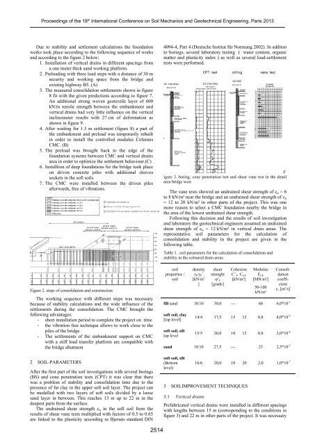
Proceedings <strong>of</strong> the 18 th International Conference on Soil Mechanics <strong>and</strong> Geotechnical Engineering, Paris 2013Due to stability <strong>and</strong> settlement calculations the foundationworks took place according to the following sequence <strong>of</strong> works<strong>and</strong> according to the figure 2 below:1. Installation <strong>of</strong> <strong>vertical</strong> <strong>drains</strong> in different spacings froma one meter thick s<strong>and</strong> working platform.2. Preloading with three load steps with a distance <strong>of</strong> 30 msecurity <strong>and</strong> working space from the bridge <strong>and</strong>existing highway B5. (A)3. The measured consolidation settlements shown in figure8 fit with the given predictions according to figure 7.An additional strong woven geotextile layer <strong>of</strong> 600kN/m tensile strength between the embankment <strong>and</strong><strong>vertical</strong> <strong>drains</strong> had very little influence on the <strong>vertical</strong>inclinometer results with 27 cm <strong>of</strong> deformation asshown in figure 9.4. After waiting for 1.3 m settlement (figure 8) a part <strong>of</strong>the embankment <strong>and</strong> preload was temporarily rebuiltin order to install the controlled modulus ColumnsCMC. (B)5. The preload was brought back to the edge <strong>of</strong> thefoundation systems between CMC <strong>and</strong> <strong>vertical</strong> <strong>drains</strong>area in order to optimize the settlement behaviour.(C)6. Installtion <strong>of</strong> deep foundations for the bridge took placeon driven concrete piles with additional sleevessockets in the s<strong>of</strong>t soils.7. The CMC were installed between the driven pilesafterwards, free <strong>of</strong> vibrations.Figure 2. steps <strong>of</strong> consolidation <strong>and</strong> constructionThe working sequence with different steps was necessarybecause <strong>of</strong> stability calculations <strong>and</strong> the wide influence <strong>of</strong> thesettlements during the consolidation. The CMC brought thefollowing advantages:- short installation period to complete the project on time- the vibration free technique allows to work close to thepiles <strong>of</strong> the bridge- The settlements <strong>of</strong> the embankment support on CMCwith a stiff load transfer platform are compatible withthe bridge abutment2 SOIL-PARAMETERSAfter the first part <strong>of</strong> the soil investigations with several borings(BS) <strong>and</strong> cone penetration tests (CPT) it was clear that therewas a problem <strong>of</strong> stability <strong>and</strong> consolidation time due to thepresence <strong>of</strong> <strong>fat</strong> <strong>clay</strong> in the upper s<strong>of</strong>t soil layer. The project canbe modelled with two layers <strong>of</strong> s<strong>of</strong>t soils divided by a looses<strong>and</strong> layer in between. This reaches 13 m up to 22 m in thedeepest parts from the surface.The undrained shear strength c u in the s<strong>of</strong>t soil from theresults <strong>of</strong> shear vane tests multiplied with factors <strong>of</strong> 0.5 to 0.65are linked to the plasticity according to Bjerum st<strong>and</strong>ard DIN4094-4, Part 4 (Deutsche Institut für Normung 2002). In additonto borings, several laboratory testing ( water content, organicmatter <strong>and</strong> plasticity index ) as well as several load-settlementtests were performed.Figure 3. boring, cone penetration test <strong>and</strong> shear vane test in the detailarea bridge westThe vane tests showed an undrained shear strength <strong>of</strong> c u = 6to 8 kN/m² near the bridge <strong>and</strong> an undrained shear strength <strong>of</strong> c u= 12 to 20 kN/m² in other parts <strong>of</strong> the project. This was onemore reason to select a CMC foundation nearby the bridge inthe area <strong>of</strong> the lowest undrained shear strength.Following this decision <strong>and</strong> the results <strong>of</strong> soil investigation<strong>and</strong> laboratory the geotechnical engineers assumed an undrainedshear strength <strong>of</strong> c u = 12 kN/m² in <strong>vertical</strong> drain areas. Therepresentative soil parameters for the calculation <strong>of</strong>consolidation <strong>and</strong> stability in the project are given in thefollowing table.Table 1 . soil parameters for the calculation <strong>of</strong> consolidation <strong>and</strong>stability in the coloured drain areassoilproperties /soildensityγ k /γ k ’[kN/m 3]shearstrenghtφ’ k[grade]CohesionC’ ,k C u,k[kN/m²]ModulusE s,k[MN/m²]50-100kN/m²Consolidationcoefficientc v [m²/s]fill s<strong>and</strong> 18/10 30,0 --- 60 6,0*10 -1s<strong>of</strong>t soil, <strong>clay</strong>[top level]s<strong>of</strong>t soil, silttop level14/4 17,5 15 12 0,8 8,0*10 -915/5 20,0 10 12 0,8 2,0*10 -8s<strong>and</strong> 18/10 27,5 --- 25 2,5*10 -3s<strong>of</strong>t soil, silt(Bottomlevel)16/6 20,0 10 20 2,0 1,0*10 -73 SOILIMPROVEMENT TECHNIQUES3.1 Vertical <strong>drains</strong>Prefabricated <strong>vertical</strong> <strong>drains</strong> were installed in different spacingswith lengths between 15 m (corresponding to the conditions infigure 3) <strong>and</strong> 22 m in other parts <strong>of</strong> the project. It was necessary2514