Double Slit Interference and Single Slit Diffraction
Double Slit Interference and Single Slit Diffraction
Double Slit Interference and Single Slit Diffraction
Create successful ePaper yourself
Turn your PDF publications into a flip-book with our unique Google optimized e-Paper software.
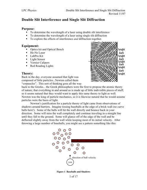
LPC Physics<strong>Double</strong> <strong>Slit</strong> <strong>Interference</strong> <strong>and</strong> <strong>Single</strong> <strong>Slit</strong> <strong>Diffraction</strong>Revised 11/07Notice also that there are lines where crests meet up with troughs:Figure 9 Destructive <strong>Interference</strong>As you already know, in the areas where there crests meet with other crests, there isconstructive interference, which doubles the amplitude of the wave, <strong>and</strong> in areas wherecrests meet with troughs there is destructive interference, which cancels out the amplitudeof the wave. If we took a snapshot of the interfering ripples, this is what they would looklike:Figure 10Interfering waves: computer simulation created by Johnny Erickson, Salt Lake Community College.Check out the animation at http://www.slcc.edu/schools/hum_sci/physics/designers/erickson/The gray fuzzy stripes are areas of total destructive interference. The surface of the wateris the same as the undisturbed (equilibrium) water level. The black <strong>and</strong> white stripes areareas of constructive interference, with total constructive interference (the highestamplitudes) occurring in the centers of the b<strong>and</strong>s.Looking at the side of the image, we could mark out the points of total constructive <strong>and</strong>destructive interference:CDCDCFigure 114 of 17
LPC Physics<strong>Double</strong> <strong>Slit</strong> <strong>Interference</strong> <strong>and</strong> <strong>Single</strong> <strong>Slit</strong> <strong>Diffraction</strong>Revised 11/07Figure 14Path-length difference is one whole wavelength: Listener hears constructive interferenceFigure 15Path-length difference is one <strong>and</strong> one-half wavelengths: Listener “hears” destructive interferenceIf the path length from one source to the listener differs by a whole number ofwavelengths from the path length of the other source to the listener, the listener willexperience total constructive interference. If the path length difference is a wholenumber plus one-half wavelengths, the listener will experience total destructiveinterference. The same will be true in two or more dimensions as well.Source ASource BPoint of Destructive<strong>Interference</strong>Figure 16Path A: L A = 2.5 wavelengths Path B: L B = 2 wavelengths∆L = L A – L B = 0.5 wavelengths6 of 17
LPC Physics<strong>Double</strong> <strong>Slit</strong> <strong>Interference</strong> <strong>and</strong> <strong>Single</strong> <strong>Slit</strong> <strong>Diffraction</strong>Revised 11/07Figure 25<strong>Diffraction</strong> pattern created by the illumination of a penny, with the penny positioned midway between thescreen <strong>and</strong> light source. Note the bright spot at the center. Serway <strong>and</strong> Jewitt, 6 th Edition, pg. 1207Why do we see a diffraction pattern when there is only one source of light? Huygens’Principle proposes that every point on a wave crest – or wave front – behaves as thoughit itself were a point source sending out another set of wave fronts. Thus, each wavefront is made up of tinier wave fronts, or wavelets.secondarySourcesourcenewwavefrontwavefrontwaveletsFigure 26 Wavefronts <strong>and</strong> WaveletsThus, each wave front (whether circular or linear) consists of hundreds of “sources”.Each of these sources sends out circular waves (whether the overall pattern is circular orlinear), <strong>and</strong> a tangent line to these “wavelets” forms the new wave front...what we wouldusually think of as the primary wavefront moving forward in space.Because each point on a wavefront can be thought of as a source, when a linearwave passes through an opening in a barrier (or a single slit), the wavelets from one“point source” can interfere with the wavelets from a second “point source”, similar towhat we discussed earlier in the case of two-slit interference. However, instead of havingonly two point sources, the wavelet theory proposes an infinite number of point sources.5a43a/2θ 2a/2 1asinθ2Figure 27 <strong>Single</strong> <strong>Slit</strong> as Many Sources11 of 17
LPC Physics<strong>Double</strong> <strong>Slit</strong> <strong>Interference</strong> <strong>and</strong> <strong>Single</strong> <strong>Slit</strong> <strong>Diffraction</strong>Revised 11/07Let us look at “sources” 1 <strong>and</strong> 3. The rays of light traveling from these sources at someangle q will meet at a point on a screen that is a sufficiently far distance L away. Ray 1must travel a distance a / 2 sinθ further than Ray 3. If this distance, a / 2 sinθ is equal to onehalfwavelength, then the waves will interfere destructively. This will be true for any tworays separated by a distance of half the slit width, a / 2 . Thus, we will find destructiveinterference when:a λsinθ=2 2or .λsinθ=aWe can see that all the light rays in the top half of the opening interfere destructively allthe light rays in the bottom half of the opening at an angle θ such that sin θ = λ . If weaimagine dividing the opening into four equal areas, then the top quarter will interfere thesecond quarter when:a λsinθ=4 2or2λsinθ=aIf we divided the opening into six equal parts, we would find that destructive interferenceoccurs when:3λsin θ = ,a<strong>and</strong> extending the supposition we may conclude that destructive interference (dark spots)occurs whenmλ = a sin θ where m = 1,2,3,...Eq. 2Now, it is historically entrenched terminology that we refer to the interference patterngenerated by a single slit as a “diffraction pattern”. This is a misnomer – diffraction isthe bending of light waves around corners. The appearance of a pattern of light <strong>and</strong> darkareas behind a single slit is, as explained above, due to the interference of a light wavewith itself. However, perhaps to differentiate between the one set-up <strong>and</strong> the other, werefer to “double-slit interference” <strong>and</strong> “single-slit diffraction”.This is where the modification to Young’s original experiment shows itscomplications. Because a set of double slits is made up of, well, two single slits, thepattern you will see is a superposition of the double-slit interference pattern on top of thesingle-slit diffraction pattern. It is the single-slit diffraction pattern that generates theintensity fall-off. If the ratio of the slit-separation to slit-width, d/a, is an integer, one ofthe interference maxima will be suppressed by a diffraction minimum. Exactly why isleft as an exercise for the student. 44 The theory for this lab was written by Jennifer LK Whalen12 of 17
LPC PhysicsExperiment And Analysis:Part A: <strong>Double</strong> <strong>Slit</strong> <strong>Interference</strong>1. Choose slide 9165-B from the optics kit.<strong>Double</strong> <strong>Slit</strong> <strong>Interference</strong> <strong>and</strong> <strong>Single</strong> <strong>Slit</strong> <strong>Diffraction</strong>Revised 11/072. Set up the laser at one end of the optics bench, with the slide in a holder directly infront of it. You can line up the laser beam <strong>and</strong> the slits by looking from the back(laser side) of the slide. Do Not look through the slits at the laser beam! Start withdouble slit (A).3. Place a screen approximately 2 meters from the double slits. Measure this distance, L.screendouble slit slidelaserFigure 284. An interference pattern of bright laser dots (maxima) <strong>and</strong> dark spaces (minima)should appear on the screen. Measure the distance between the farthest dot on the left<strong>and</strong> the farthest dot on the right. Divide this distance by [number of dots minus 1] todetermine the distance, x, between two sequential dots.Pscreen <strong>and</strong>interference patternn = 4n = 2n = 0 n = 2n = 4n = 5 n = 3 n = 1 n = 1 n = 3 n = 5xx = P/10(in this example...your denominator may be different!)Figure 295. Divide the distance between dots, x, by the distance from the slits to the screen. Thisis a measure of tanθ. If x is quite small <strong>and</strong> L is quite large, then tanθ≈ θ ≈ sinθ.Thus, we will use this measurement to be equal to sinθ.13 of 17
LPC Physics<strong>Double</strong> <strong>Slit</strong> <strong>Interference</strong> <strong>and</strong> <strong>Single</strong> <strong>Slit</strong> <strong>Diffraction</strong>Revised 11/07xscreen <strong>and</strong>interference patternLdouble slit slidelaserFigure 306. From the interference equation, nλ=d sinθ; where n is the maxima number (equal to 1for your calculation), d is the distance between the slits, <strong>and</strong> sinθ is the number fromstep (5); determine λ, the wavelength of the laser light.7. Repeat steps 2-6 with slits (B), (C) <strong>and</strong> (D).8. Present your data in a neat table. Determine, from your measurements, the averagevalue of λ, <strong>and</strong> its uncertainty.9. Does your value of λ agree with the actual value of λ for a Helium-Neon laser, λ =632.9 nm, within your experimental uncertainty (i.e. is λ meas –σ < λ actual < λ meas +σ,where σ is your uncertainty)?Part B: <strong>Single</strong> <strong>Slit</strong> <strong>Diffraction</strong>1. Replace the double slit slide with the single-slit source, 9165-A. Use slit (B) first.2. As in Part A, place a screen approximately 2m from the slits, <strong>and</strong> measure thisdistance, L.3. A diffraction pattern of horizontal “bars” should appear on the screen, morewidely spaced than the dots from Part A. The bright bars are the maxima, <strong>and</strong> thedark spaces are the minima. We use a similar equation for diffraction as forinterference, but we count minima instead of maxima. Using a measurementprocedure similar to that in Part A, determine the distance, x, between subsequentminima. Remember: this distance may be measured as the length between the centers14 of 17
LPC Physics<strong>Double</strong> <strong>Slit</strong> <strong>Interference</strong> <strong>and</strong> <strong>Single</strong> <strong>Slit</strong> <strong>Diffraction</strong>Revised 11/07of neighboring maxima, the length from the leading edge of one maximum to theleading edge of the next, or as drawn, the length between the centers of neighboringminima. Do not include the central maximum in your calculations, because it islarger than the other maxima <strong>and</strong> will throw-off your calculations.xscreen <strong>and</strong>diffraction patternm = 2 m = 1m = 1 m = 2Figure 314. From the interference equation, m λ = asinθ, where a is the slit width, <strong>and</strong> m is theminima-number, determine the wavelength of the laser light. You will have to use asimilar trigonometric approximation as in the double-slit measurement of wavelength.5. Repeat the measurement with slit (D).6. Present your data in a neat table. Determine a second experimental value of λ. Doesyour value agree with the actual value of λ for a He-Ne laser?7. Determine which experiment, Part A or Part B gives a better experimental value ofthe wavelength of a He-Ne laser, <strong>and</strong> explain why.Part C. <strong>Double</strong> <strong>Slit</strong> <strong>Interference</strong> with <strong>Single</strong> <strong>Slit</strong> <strong>Diffraction</strong>.1. Replace the single slit source with the double slit source. Re-establish theinterference patter on the screen with slits (B). This time, take note that the doubleslitinterference pattern of small, evenly spaced dots is not constant, but fades in <strong>and</strong>out. If you st<strong>and</strong> back from the screen, the dots should blend into the bars of thesingle slit diffraction pattern that is superposed on the double slit pattern.+screen <strong>and</strong>diffraction pattern=m = 3 double-slit maximum is suppressedm = 6 double-slit maximum is suppressedFigure 322. Find the first <strong>and</strong> second order minima for the (single slit) diffraction pattern.15 of 17
LPC Physics<strong>Double</strong> <strong>Slit</strong> <strong>Interference</strong> <strong>and</strong> <strong>Single</strong> <strong>Slit</strong> <strong>Diffraction</strong>Revised 11/073. Measure x. Calculate a. (mλ = a sinθ ) (As before, you will need to usetrigonometric approximations!)4. Estimate the uncertainty in a.5. Observe which interference maximum is suppressed by the 1st order diffractionminimum (i.e. which maximum from the double slit pattern is canceled out by theminimum of the single slit interference pattern).6. Compare the order of this suppressed maximum with the ratio d/a. Derive anequation that explains your findings.7. Repeat (1-6) with double slits (A) <strong>and</strong> (C).D. Measuring the Intensity PatternIn this section you will directly measure the intensity as a function of displacement, x,using the Vernier light probe <strong>and</strong> motion sensor with Logger Pro.1. Clamp the light sensor onto a st<strong>and</strong>. The sensor will need to be level with the laser<strong>and</strong> pointed directly at it. Tape a piece of cardstock to the side of the rod above thelight sensor so that the motion detector can pick it up. Tape a meter stick to the table,making sure that it is perpendicular to the axis of the optical bench. This will help tokeep the sensor at the same distance from the source.2. Plug in the LabPro <strong>and</strong> connect it to the computer with a USB cable. Connect thelight sensor <strong>and</strong> motion sensor to the Lab Pro.3. Open the Experiments folder on the desktop <strong>and</strong> open the file diffract.xmbl (or.cmbl) This will start the program Logger Pro3.5 <strong>and</strong> bring up the appropriate datafile.4. Set the intensity switch on the light sensor to 600 lux.5. Place the double slit in the path of the laser beam, <strong>and</strong> project the interference patternon a screen. Move the slide around on the carrier until you get the brightestinterference pattern.6. Remove the screen. You are ready to take data now. Two problems can arise:a. The motion detector does not read distance correctly. If this occurs, makesure that the cardstock is at least 40cm away from the motion detectorthroughout the experiment. Also make sure the detector is level with the cardstock <strong>and</strong> that the path from the detector to the cardstock is exactlyperpendicular.b. The light detector isn’t picking anything up. In this case, make sure the sensoris set to 600 lux. Place the detector in the bright central maximum region <strong>and</strong>make sure that the beam is centered on the detector. Also check to make surethat the diffraction pattern is exactly horizontal. If it isn’t, then moving the16 of 17
LPC Physics<strong>Double</strong> <strong>Slit</strong> <strong>Interference</strong> <strong>and</strong> <strong>Single</strong> <strong>Slit</strong> <strong>Diffraction</strong>Revised 11/07detector side to side can result in losing the signal as the pattern migrates upor down.7. Hit the Collect button <strong>and</strong> slowly move the detector across the diffraction pattern,using the meter stick on the table to ensure that you do not move the detector closeror farther from the source.8. Plot intensity vs. displacement for your interference pattern <strong>and</strong> turn in this plot withyour report. Be sure to identify the important features of your plot (i.e. maxima <strong>and</strong>minima).9. Replace the double slit with a single slit <strong>and</strong> repeat Steps 5-12.10. For the single slit pattern, compare the intensity of the central maximum to theintensity of the next two largest maximums from your experimental data. Is this ratioin agreement with the value predicted for the intensity of a single slit interferencepattern?11. Optional: Export your double slit data to graphical analysis. Create a calculatedcolumn converting your displacement data to angle θ. The theoretical formula for thediffraction pattern intensity iswherekbβ = sinθ2kaα = sinθ2I24 ⎛ sin β0cosβ ⎟ ⎞⎜⎝ ⎠2( θ ) = I ⎜α, a is the separation between slits, b is the slit width, <strong>and</strong>k is the wave number,2πk = .λPlot intensity vs. θ, <strong>and</strong> perform a curve fit to the data using your values for a <strong>and</strong> b whileleaving I 0<strong>and</strong> k as parameters. How does the value of k obtained by the curve fitcompare to the actual value?17 of 17


