Relief: A Modeling by Drawing Tool
Relief: A Modeling by Drawing Tool
Relief: A Modeling by Drawing Tool

You also want an ePaper? Increase the reach of your titles
YUMPU automatically turns print PDFs into web optimized ePapers that Google loves.
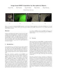
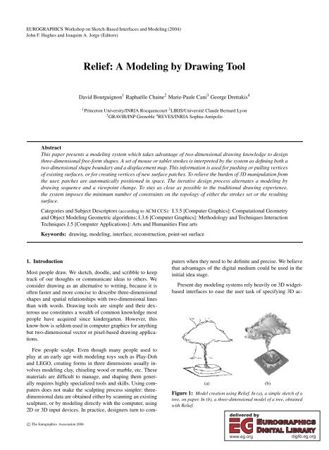
EUROGRAPHICS Workshop on Sketch-Based Interfaces and <strong>Modeling</strong> (2004)John F. Hughes and Joaquim A. Jorge (Editors)<strong>Relief</strong>: A <strong>Modeling</strong> <strong>by</strong> <strong>Drawing</strong> <strong>Tool</strong>David Bourguignon 1 Raphaëlle Chaine 2 Marie-Paule Cani 3 George Drettakis 41 Princeton University/INRIA Rocquencourt 2 LIRIS/Université Claude Bernard Lyon3 GRAVIR/INP Grenoble 4 REVES/INRIA Sophia-AntipolisAbstractThis paper presents a modeling system which takes advantage of two-dimensional drawing knowledge to designthree-dimensional free-form shapes. A set of mouse or tablet strokes is interpreted <strong>by</strong> the system as defining both atwo-dimensional shape boundary and a displacement map. This information is used for pushing or pulling verticesof existing surfaces, or for creating vertices of new surface patches. To relieve the burden of 3D manipulation fromthe user, patches are automatically positioned in space. The iterative design process alternates a modeling <strong>by</strong>drawing sequence and a viewpoint change. To stay as close as possible to the traditional drawing experience,the system imposes the minimum number of constraints on the topology of either the strokes set or the resultingsurface.Categories and Subject Descriptors (according to ACM CCS): I.3.5 [Computer Graphics]: Computational Geometryand Object <strong>Modeling</strong> Geometric algorithms; I.3.6 [Computer Graphics]: Methodology and Techniques InteractionTechniques J.5 [Computer Applications]: Arts and Humanities Fine artsKeywords: drawing, modeling, interface, reconstruction, point-set surface1. IntroductionMost people draw. We sketch, doodle, and scribble to keeptrack of our thoughts or communicate ideas to others. Weconsider drawing as an alternative to writing, because it isoften faster and more concise to describe three-dimensionalshapes and spatial relationships with two-dimensional linesthan with words. <strong>Drawing</strong> tools are simple and their dexteroususe constitutes a wealth of common knowledge mostpeople have acquired since kindergarten. However, thisknow-how is seldom used in computer graphics for anythingbut two-dimensional vector or pixel-based drawing applications.Few people sculpt. Even though many people used toplay at an early age with modeling toys such as Play-Dohand LEGO, creating forms in three dimensions usually involvesmodeling clay, chiseling wood or marble, etc. Thesematerials are difficult to manage, and shaping them generallyrequires highly specialized tools and skills. Using computersdoes not make the sculpting process simpler: threedimensionaldata are obtained either <strong>by</strong> scanning an existingsculpture, or <strong>by</strong> modeling directly with the computer, using2D or 3D input devices. In practice, designers turn to computerswhen they need to be definite and precise. We believethat advantages of the digital medium could be used in theinitial idea stage.Present day modeling systems rely heavily on 3D widgetbasedinterfaces to ease the user task of specifying 3D ac-(a)Figure 1: Model creation using <strong>Relief</strong>. In (a), a simple sketch of atree, on paper. In (b), a three-dimensional model of a tree, obtainedwith <strong>Relief</strong>.(b)c○ The Eurographics Association 2004.
152D. Bourguignon, R. Chaine, M.-P. Cani, and G. Drettakis / <strong>Relief</strong>: A <strong>Modeling</strong> <strong>by</strong> <strong>Drawing</strong> <strong>Tool</strong>tions using 2D input devices. This way, the user visualizesthe task <strong>by</strong> looking at the 3D scene from several viewpoints,such as the traditional blueprint projection planes. The underlyingrationale is that a 3D task is better performed using3D tools [CSH ∗ 92]. This is true; however, these tools aregenerally controlled using 2D input devices, and this resultsin nonintuitive, advanced-user-oriented systems.The inverse approach has received far less attention. Sincemost of the input devices we have are two-dimensional, webelieve that 2D tools are more appropriate to perform 3Doperations. This way, the user is able to visualize the taskcompletely from only one viewpoint, i.e., the current cameraimage plane. The most simple 2D tools, that take advantageof all the expressive capabilities of a human hand, aredrawing tools.To stay as close as possible to the traditional drawingexperience, our system input must consist of just plainstrokes. They are interpreted <strong>by</strong> the system as defining a twodimensionalshape boundary and a displacement map. Theformer is computed using a curve reconstruction algorithm.The latter is obtained <strong>by</strong> following a simple shading convention.Together, they are used for pushing or pulling verticesof existing surfaces, or for creating vertices of new surfacepatches. (These new patches are attached or not to existingsurfaces.)In order to relieve the burden of three-dimensional manipulationfrom the user, new surface patches are positionedin space according to a few simple rules. Our surface representationhandles arbitrary topology changes without thedrawbacks of either polygonal meshes (difficult to edit andmaintain through deformations) or voxel grids (storage overheadand signal aliasing). It is based on points and a surfacereconstruction algorithm which is the three-dimensionalequivalent of the algorithm mentionned above.The iterative design process alternates a modeling <strong>by</strong>drawing sequence and a viewpoint change. Its output is athree-dimensional triangular mesh that fits easily in the standardcomputer graphics production pipeline.Our system reuses some of the ideas proposed <strong>by</strong> previousmodeling systems, such as specification of displacementthrough shading, and depth determination through projectionon existing surface. However, it overcomes three of their keylimitations. First, it formulates the two-dimensional shapefrom strokes problem as a curve reconstruction problem andthus handles most stroke input with ease. Second, it imposesno constraint on the appearance and topology of the surfaceduring the design session, thus freeing the user from theburden of planning its entire sculpture process in advance.Third, it does not limit modeling operations to modificationsof the initial surface, thus allowing a wider range of resultingshapes.2. Related WorkSince the invention of Sketchpad <strong>by</strong> Ivan Sutherland in1963 [Sut63], many computer graphics systems have useddrawing metaphors for 3D shape modeling, most oftenrequiring the user to draw polyhedral surfaces in wireframe[LS96, SC04]. However, this CAD atavism keepsthese solutions out of reach of common drawing practice.Notably, Eggli et al. alleviate this burden of unintuitive input<strong>by</strong> using simple drawing techniques that have an unambiguousinterpretation in three dimensions [EBE95].Departing from these approaches, SKETCH and Teddydemonstrated that gesture-based interfaces are powerful andintuitive tools for 3D model design [ZHH96, IMT99]. However,they trade their simplicity against limitations on theappearance (boxy, rotund) or topology of models generated.Concerning Teddy, the latter problem has been addressed usingeither variational implicit surfaces [KHR02] or a volumetricshape representation [ONNI03].In systems mentioned previously, drawing is used for describingboundaries and shape features using strokes, but notas a way of modeling the relief of surfaces. In his pioneeringwork, Williams proposes to create a height field <strong>by</strong> directlypainting the luminance value corresponding to a given elevation[Wil90]. On the contrary, the GRADED system usesshading information to infer a gradient map and a consistentdepth map [van96]. Inspired <strong>by</strong> these attempts, a modelingtool based on a shape-from-shading algorithm has been proposedfor surface retouching [RGB ∗ 03]. However, it is tooslow for interactive use and requires photorealistic shading,which is difficult to obtain <strong>by</strong> drawing.Three interesting solutions to the modeling <strong>by</strong> drawingproblem are found in commercial systems. Artisan is a Mayasoftware toolset with a common painting metaphor [Ali04],inspired from interactive texturing interfaces [HH90]. TheSculpt Polygons <strong>Tool</strong> pushes, pulls, or smoothes the surfacewhen the user paints it with the corresponding brush.ZBrush greatly expands the mesh editing operations ofMaya’s Artisan [Pix04]. The user first sculpts a rough shapeenvelope using ZSpheres, and then refines it thanks toits subdivision surface multiresolution capabilities. Finally,SketchUp is a thorough architecture design system, inspired<strong>by</strong> SKETCH [@La04].3. <strong>Tool</strong> WorkflowThe <strong>Relief</strong> system is a modeling <strong>by</strong> drawing tool, i.e., modelingoperations are achieved <strong>by</strong> drawing. The user drawsonly on the image plane, never directly on the objects ofthe scene. However, drawing operations take into accountthree-dimensional information, such as visibility and depth,<strong>by</strong> performing image queries in buffers, such as ID and depthbuffers, using the graphics hardware.c○ The Eurographics Association 2004.
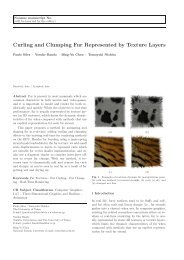
154D. Bourguignon, R. Chaine, M.-P. Cani, and G. Drettakis / <strong>Relief</strong>: A <strong>Modeling</strong> <strong>by</strong> <strong>Drawing</strong> <strong>Tool</strong>¡¡¡¡¡¡¡¡¡¡¢¡¢¡¢¡¢¡¢¡¢¡¢¡¢¡¢¡¢¡¢¡¢¡¡¡¡¡¡¡¡¡¡¡¢¡¢¡¢¡¢¡¢¡¢¡¢¡¢¡¢¡¢¡¢¡¢¡¡¡¡¡¡¡¡¡¡¡¢¡¢¡¢¡¢¡¢¡¢¡¢¡¢¡¢¡¢¡¢¡¢¡¡¡¡¡¡¡¡¡¡¡¢¡¢¡¢¡¢¡¢¡¢¡¢¡¢¡¢¡¢¡¢¡¢¡¡¡¡¡¡¡¡¡¡¡¢¡¢¡¢¡¢¡¢¡¢¡¢¡¢¡¢¡¢¡¢¡¢¡¡¡¡¡¡¡¡¡¡¡¢¡¢¡¢¡¢¡¢¡¢¡¢¡¢¡¢¡¢¡¢¡¢¡¡¡¡¡¡¡¡¡¡¡¢¡¢¡¢¡¢¡¢¡¢¡¢¡¢¡¢¡¢¡¢¡¢¡¡¡¡¡¡¡¡¡¡¡¢¡¢¡¢¡¢¡¢¡¢¡¢¡¢¡¢¡¢¡¢¡¢¡¡¡¡¡¡¡¡¡¡¡¢¡¢¡¢¡¢¡¢¡¢¡¢¡¢¡¢¡¢¡¢¡¢¡¡¡¡¡¡¡¡¡¡¡¢¡¢¡¢¡¢¡¢¡¢¡¢¡¢¡¢¡¢¡¢¡¢¡¡¡¡¡¡¡¡¡¡¡¢¡¢¡¢¡¢¡¢¡¢¡¢¡¢¡¢¡¢¡¢¡¢¡¡¡¡¡¡¡¡¡¡¡¢¡¢¡¢¡¢¡¢¡¢¡¢¡¢¡¢¡¢¡¢¡¢¡¡¡¡¡¡¡¡¡¡¡¢¡¢¡¢¡¢¡¢¡¢¡¢¡¢¡¢¡¢¡¢¡¢¡¡¡¡¡¡¡¡¡¡¡¢¡¢¡¢¡¢¡¢¡¢¡¢¡¢¡¢¡¢¡¢¡¢¡¡¡¡¡¡¡¡¡¡¡¢¡¢¡¢¡¢¡¢¡¢¡¢¡¢¡¢¡¢¡¢¡¢¡¡¡¡¡¡¡¡¡¡¡¢¡¢¡¢¡¢¡¢¡¢¡¢¡¢¡¢¡¢¡¢¡¢¡¡¡¡¡¡¡¡¡¡¡¢¡¢¡¢¡¢¡¢¡¢¡¢¡¢¡¢¡¢¡¢¡¢¡¡¡¡¡¡¡¡¡¡¡¢¡¢¡¢¡¢¡¢¡¢¡¢¡¢¡¢¡¢¡¢¡¢¡¡¡¡¡¡¡¡¡¡¡¢¡¢¡¢¡¢¡¢¡¢¡¢¡¢¡¢¡¢¡¢¡¢¡¡¡¡¡¡¡¡¡¡¡¢¡¢¡¢¡¢¡¢¡¢¡¢¡¢¡¢¡¢¡¢¡¢¡(a) (b) (c)Figure 3: The two-dimensional convection process. In (a), before the convection starts. The pseudo-curve lies on oriented edges of theDelaunay triangulation of the point set. In (b), the pseudo-curve evolves as long as the Gabriel criterion is not met for every oriented edge(half-disk, in red, associated with an oriented edge, in green). In (c), after the convection stopped. The result of the process is a topologicallyconsistent set of oriented edges; it can contain coupled oriented edges called thin parts (the “tail” at the bottom right of the shape).In both cases, our reconstruction algorithm must satisfyseveral requirements:• It must be able to handle an arbitrary number of connectedcomponents to allow modeling of an entire scene, containingmany objects.• It must be able to handle outliers, i.e., points located offshape boundaries. For example, in the two-dimensionalcase, strokes can describe either geometry or texture information,and thus do not always lie on the silhouette ofthe shape.• It must be sufficiently fast to allow interactivity foraverage-sized point sets (around 5 × 10 3 points).Our first attempt to solve this reconstruction problemwas successful in 2D, but did not generalize well to3D [Bou03]. However, a recent method meets all the requirementspreviously listed, for two- and three-dimensionalpoint sets [Cha03]. We will describe this reconstruction algorithmand illustrate its key features in the two-dimensionalcase.The reconstruction algorithm proposed <strong>by</strong> Chaine is basedon an analogy with a physical phenomenon, convection. Letus consider a curve around a two-dimensional point set. Underthe influence of convection forces, each point of thecurve will move towards its nearest neighbor in the pointset, with possible topological changes occurring during theevolution of the curve.This process can be translated in computational geometryterms <strong>by</strong> evolving a data structure called pseudo-curve inthe two-dimensional Delaunay triangulation of the point set.The pseudo-curve lies on oriented edges of the triangulation(see Fig. 3a), and it evolves as long as the half-disk associatedwith an oriented edge contains a point, i.e., an orientededge does not meet the Gabriel criterion (see Fig. 3b). Theresult of the convection process is a topologically consistentset of oriented edges. For some point sets, this result containscoupled oriented edges, i.e., oriented edges with oppositeorientations, that are geometrically dependent, but canbe topologically independent. These coupled oriented edgesare called thin parts (see Fig. 3c).The resulting set of oriented edges can be partially or entirelymade of thin parts, when the corresponding point setdescribes a non-manifold shape. (In the first step of our algorithm,described in Sec. 3.1, a set of oriented edges entirelymade of thin parts is rejected, since it does not define a shapewith one or several boundaries.)Note that the convection process cannot correctly reconstructa particular type of concavity called a pocket. To addressthis issue, pockets are detected during the evolutionof the pseudo-curve, <strong>by</strong> comparing the size of each orientededge with the local density, assuming that, unless the edgeleads to a pocket, the edge size of a well-sampled object isconsistent with the local density (see Fig. 4a).In three dimensions, this convection approach is extendedto a pseudo-surface evolving in the three-dimensional Delaunaytriangulation of a point set. The result of the con-(c)(a)Figure 4: Convection pocket and collapse. In (a), an example ofpocket. The size of the pocket edge (red half-disk) is larger than thesize of two of its incident edges (blue half-disks). In (b), before acollapse of the pseudo-curve. In (c), after a collapse of the pseudocurve.In 2D, a collapse is always caused <strong>by</strong> a pocket. In 3D, sixpossible collapse cases correspond to different topological changesof the pseudo-surface occuring during the convection process.(b)c○ The Eurographics Association 2004.
D. Bourguignon, R. Chaine, M.-P. Cani, and G. Drettakis / <strong>Relief</strong>: A <strong>Modeling</strong> <strong>by</strong> <strong>Drawing</strong> <strong>Tool</strong>155vection process is a topologically consistent set of orientedfacets.We implemented the two algorithms using the 2D and 3Dtriangulation packages of the Computational Geometry AlgorithmsLibrary [CGA04].5. Adaptive SamplingAfter the first step (Sec. 3.1) of the modeling <strong>by</strong> drawingsequence has been completed, we face in the second step(Sec. 3.2) the following problem: given displacement regionsin image space, and given an existing surface in worldspace, will the displacement values be correctly sampled <strong>by</strong>the existing surface vertices projected in image space? In thecase of a highly refined surface whose projection entirelycovers the displacement regions, this will probably be true.However, for all the other cases (poorly refined surface, projectionnot covering all the displacement regions), we haveto address this issue.Finding an optimal sampling of the displacement regionsamounts to finding an error map that will provide informationabout the areas that need to be sampled more than others.We evaluate this error map <strong>by</strong> simply projecting the existingsurface vertices onto the image plane, giving them adisplacement value <strong>by</strong> looking for the value at the correspondingposition in the displacement map (see Fig. 5a), andrendering the corresponding 2D Delaunay triangulation usingthe graphics hardware, i.e., <strong>by</strong> linear interpolation of thedisplacement values, considered as grayscale color attributesof the vertices (see Fig. 5b). The absolute value of the differencebetween this approximate displacement map and thetrue displacement map gives us an error map (see Fig. 5c).This error map is then adaptively sampled (see Fig. 5d)using a fast and accurate error-diffusion algorithm [ZF03].This sampling method is inspired from interactive geometryremeshing techniques [AMD02]. It allows a simple tuningof the sampling rate <strong>by</strong> a linear scaling of the values of theerror map.If the projection of the existing surface does not coverall the displacement regions, or if there is no existing surfaceat all, corresponding parts of the approximate displacementmap are filled with an arbitrary continuous value (seeFig. 5c), in order to prevent these areas from not being sampled.6. Depth InferenceOnce the displacement regions have been adaptively sampledas described in Sec. 5, each new sample can be consideredas a three-dimensional surface vertex projected onthe image plane, with a known displacement value, but anunknown depth value. Our problem amounts to defining thedepth of these new vertices in order to compute their threedimensionalposition <strong>by</strong> “unprojection” from image space toworld space.(a) (b) (c)(d) (e) (f)Figure 5: Adaptive sampling and depth inference. (Same exampleas the one presented on Fig. 2.) In (a), the corresponding displacementmap. In (b), the approximate displacement map, obtained <strong>by</strong>sampling the displacement map with the projections of the existingsurface vertices. In (c), the error map corresponding to the differencebetween (a) and (b): the darker the tone, the larger the error.In (d), the adaptive sampling of the error map. In (e), the ID bufferused to identify the projections of existing surface vertices. In (f),the depth buffer corresponding to the existing surface.We infer the depth of the new vertices using the depth informationof the vertices of the existing surface. To this end,we build a 2D Delaunay triangulation of all the vertices projectedon the image plane: both the vertices of the existingsurface, with known depth value (see Fig. 5e), and the newvertices, with unknown depth value. In practice, we reusethe triangulation data structure already built in Sec. 5, simplyadding the new vertices to it.Then, starting with the vertices of unknown depth value,whose incident vertices are of known depth value, possiblythanks to a depth buffer query (see Fig. 5f), we propagatedepth information through the triangulation using a standardbest first search algorithm, i.e., a breadth first search thatuses a priority queue ordered according to, for a given vertexelement, the number of incident vertices of known depthvalue. Successively examining the vertices in the queue, weevaluate their unknown depth using an interpolation schemebased on the distance between the vertex and each of its incidentvertices of known depth value [Tau95]. As a result, theposition of new vertices interpolates, and sometimes extrapolates,the position of existing surface vertices (see Fig. 8ab).In the case the user has not drawn at all on an existingsurface, an arbitrary depth is assigned to the new vertices.This depth can be either chosen as the depth of the worldspace origin, or as the depth of a plane parallel to the imageplane and defined <strong>by</strong> the user.c○ The Eurographics Association 2004.
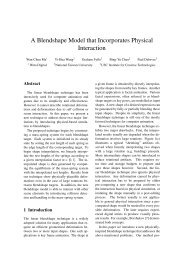
156D. Bourguignon, R. Chaine, M.-P. Cani, and G. Drettakis / <strong>Relief</strong>: A <strong>Modeling</strong> <strong>by</strong> <strong>Drawing</strong> <strong>Tool</strong>7.2. Blobbing(a) (b) (c) (d)Figure 6: Hole marks. In (a) and (b), hole marks in comic bookproduction: artwork from Stone #3, Avalon Studios. In (a), pencils<strong>by</strong> Whilce Portacio. In (b), inks <strong>by</strong> Gerry Alanguilan. Note the smallcrosses drawn <strong>by</strong> the penciler to give information about the positionsof holes to the inker. In (c), and (d), hole marks in <strong>Relief</strong>. In (c),a hole mark defined <strong>by</strong> the user. In (d), the resulting effect on the reconstructedshape boundary. (In (a) and (c), marks are colored inred for clarity.)7. <strong>Tool</strong> InterfaceWe describe in this section a few algorithms that are usedto ease the process of modeling <strong>by</strong> drawing, either to drawshapes with holes, to compute automatic shading effects, toobtain an adaptive shading-to-displacement mapping, or toperform various surface enhancement operations.7.1. Hole MarksWhen drawing a shape with holes, the definition of insideand outside parts is generally ambiguous. This problem iscommonly solved in the comic book industry: the penciler(who has actually created the drawing, see Fig. 6a), giveshints to the inker (who will overdraw in ink some of the pencillerlines, see Fig. 6b), about the parts of the drawing whichare considered foreground and the ones which are consideredbackground, that is, “holes” in the foreground.Inspired <strong>by</strong> this traditional solution to the drawing topologicalambiguity problem, we provide the user with thepossibility of marking areas considered as holes with holemarks, i.e., special strokes obtained <strong>by</strong> maintaining a modifierkey pressed while drawing (see Fig. 6c-d).These marks are taken into account after the twodimensionalshape reconstruction is over (see Sec. 3.1).First, using the 2D Delaunay triangulation, we determinethe faces intersected <strong>by</strong> each segment of a mark stroke andtag these marked faces as external to the shape. Second, inspectingeach of these faces in turn, we gather the boundaryedges, i.e., edges that belong both to a marked and a nonmarkedface. Third, these edges are used as starting edgesfor a rerun of the two-dimensional reconstruction algorithm,in the same way we used the convex hull edges in the initialreconstruction, as explained in Sec. 4.In order to speed up modeling of regular rotund shapes, inthe spirit of Teddy [IMT99], we provide a blobbing operationthat performs an automatic inflation of the drawn shape,i.e., that creates the shading corresponding to an inflation ofits silhouette.Solutions to the inflation problem can be classified as eitherobject-based [vW97] or image-based [OCDD01]. Sincethe resulting blobbing is equivalent to a shading created <strong>by</strong>the user, we chose an image-based solution. Inflation is obtainedin two steps. In the first step, we compute the Euclideandistance transform of the binary map correspondingto the drawn shape, using a fast algorithm [CM99]. Thisgives us the distance field d (x,y) (see Fig. 7a-b). In the secondstep, in order to give a rotund appearance to the shape,we map the distance field to a unit sphere height field z(x,y),i.e.,z(x,y) =√1 −(1 − d (x,y) ) 2d maxwhere d max is the maximum value of the scalar field d (seeFig. 7c). Note that the value of d max gives us a distance (inpixel units) that can be used later to estimate the mappingof the shading corresponding to the normalized height fieldin image space, to a displacement field in world space (seeSec. 7.3). Finally, the resulting shading is accumulated ontop of stroke images in the frame buffer (see Fig. 7d).7.3. Shading-to-Displacement MappingAccording to our shading convention, displacement is proportionalto the distance between a tone and the midtone (see(a)(c)(b)(d)Figure 7: Blobbing. In (a), the drawn shape. In (b), the correspondingdistance field. In (c), the corresponding unit sphere heightfield. In (d) and (e), the resulting white shading and the correspondingsurface.(e)c○ The Eurographics Association 2004.
D. Bourguignon, R. Chaine, M.-P. Cani, and G. Drettakis / <strong>Relief</strong>: A <strong>Modeling</strong> <strong>by</strong> <strong>Drawing</strong> <strong>Tool</strong>157perform fine surface edits or to prevent areas of the projectedsurface from being taken into account in subsequent depthinference computations (see Fig. 8e-f).(a) (c) (e)(b) (d) (f)Figure 8: Various depth modes. In (a) and (b), standard depthinference: the position of new vertices interpolates, and sometimesextrapolates, the position of existing surface vertices (see Sec. 6).In (c) and (d), modeling at depth: new vertices are positioned at thedepth of the closest existing surface vertice involved (see Sec. 7.4).In (e) and (f), frisket mode: where frisket has been applied (red regions),the depth of existing surface vertices is not taken into accountin standard depth inference computations (see Sec. 7.5).Sec. 3.1). However, in order to ease modeling, this mappingalso depends on two other variables.First, the mapping is proportional to the distance betweenthe point of view and a point on the existing surface, i.e.,the closer the viewpoint is to the surface, the smaller the displacements.Thus allowing the user to work with higher precisionwhen zooming on surface details. Second, the mappingis inversely proportional to the current size of the surface:a small surface will undergo only small displacements,thus avoiding the user to adjust his work to the absolute sizeof the object.7.4. <strong>Modeling</strong> At DepthInspired <strong>by</strong> Maya’s Paint Effects depth modes [Ali04], weprovide another modeling method (alternative to the one presentedabove in Sec. 3.2). This method can be useful whenthe user wants to avoid simply pushing or pulling verticeswhile drawing over an existing surface.With this method, existing surface vertices projected inimage space that fall into the displacement regions, are notinfluenced <strong>by</strong> displacement values. Moreover, the systemcomputes their smallest depth value, and this value is assignedto the new vertices (see Fig. 8c-d). This method issometimes convenient to accumulate several independentsurface patches.7.5. Frisket MaskingInspired from the liquid masking gum of the same name, afrisket mode is provided for masking the projection of theexisting surface on the image plane. This is very useful to7.6. Other Surface Editing ModesSurface editing operations, such as surface smoothing or vertexremoval, are obtained using two simple algorithms. Forsurface smoothing, we use a low-pass filtering of the surfacesignal [Tau95]. This smoothing operation is currently availableonly if the user draws with a smoothing brush. However,it could be possible to apply it after each modeling sequencein order to automatically improve the smoothness ofthe resulting surface. For vertex removal, we simply identifyvertices using an ID buffer and remove them from the threedimensionalpoint set. After each of those surface editingoperations, the surface is reconstructed to take the modificationsinto account.8. Results and DiscussionResults obtained with the <strong>Relief</strong> system are encouraging (seeFig. 9). As we mentioned in Sec. 1, our system improvesover previous systems thanks to three key features. However,our preliminary implementation has still several limitations.We will discuss them here and review the work remaining tobe done in Sec. 9.The computing time bottleneck of the system is the constructionof the three-dimensional Delaunay triangulationmentioned in Sec. 4. In fact, the complexity of the shape reconstructionalgorithms is comparable to the complexity ofthe Delaunay triangulation of the point set. For example, reconstructinga surface from 6752 points takes 1.1 s [Cha03].Three users have used our system to create models indifferent styles (compare for example the tree in Fig. 1band Fig. 9e), which is a good indication that the systempreserves the unique character of each user drawings. Wedemonstrate the actual use of the system in an accompanyingvideo (showing the creation of the tree model displayedin Fig. 1b).The informal testing of our software assessed the true benefitsof several interface choices. For example, as opposed towhat we could have expected, most users were not disturbed<strong>by</strong> the fact that the shading convention does not explicitlyprovide the exact displacement values applied. However, wefound out two intrinsic problems with our drawing metaphor.First, there is no continuous visual feedback: modelingoperations occur after the user has finished drawing, not atthe same time the user draws. An hybrid solution could combinea “synchronous” mode, for editing existing surfaces,as in commercial modeling systems [Ali04], and our “asynchronous”mode, for creating new surfaces.Second, it is difficult to obtain a continuous shading, andc○ The Eurographics Association 2004.
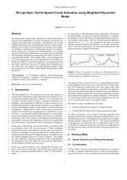
158D. Bourguignon, R. Chaine, M.-P. Cani, and G. Drettakis / <strong>Relief</strong>: A <strong>Modeling</strong> <strong>by</strong> <strong>Drawing</strong> <strong>Tool</strong>(a) (b) (c) (d)(e) (f) (g) (h)(i) (j) (k) (l)Figure 9: Various models obtained with <strong>Relief</strong>. In (a) and (b), top and other side views of a tree (2139 points), previously displayed in Fig. 1b.In (c), the corresponding point set. In (d), the same tree rendered as a polyhedral surface with facet normals (in red). In (e), another tree(1026 points), modeled in a different style than the one displayed in (a-d). In (f), an imported sphere model transformed into an elephant (3718points). In (g) and (h), a fruit basket with a lonely banana (1310 points), rendered either as a solid surface or as a polyhedral surface with facetnormals (in red). In (i), (j), and (k), three sequences of the modeling of a lion head. In (l), the final model, rendered in wireframe.thus a smooth surface, with discontinuous strokes. Providingother higher level drawing operations, in the spirit ofblobbing (see Sec. 7.2), could help the user easily achievecontinuous shadings.Finally, we would like to briefly compare our point-setsurface representation based on evolving pseudo-manifoldsurfaces [Cha03] with recently proposed point-set surfacerepresentations based on Moving Least Square (MLS) surfaces[ABCO ∗ 01, AK04]. In fact, both representations handlearbitrary topology changes without the drawbacks of eitherpolygonal meshes or voxel grids, but differences betweenthem come from the way surface points are found.Our representation amounts to finding topologically consistentsurface neighborhoods, that together define an explicitsurface. On the contrary, representations based onMLS surfaces amount to fitting a predefined surface aroundeach point, and those local surfaces define together a globalimplicit surface. In the first case, there is no local surfacemodel, and the resulting surface interpolates the point set.In the second case, there is a local surface model, and theresulting surface approximates the point set.9. Conclusion and Future WorkWe have presented <strong>Relief</strong>, a modeling <strong>by</strong> drawing tool whichstrives to stay as close as possible to the traditional drawingexperience, while enabling the user to create threedimensionalmodels. Using a shading convention relatingtone to displacement, we are able to edit existing surfacesor to create new surface patches, while imposing the minimumnumber of constraints either on the user drawing or onthe resulting model.Given our current implementation, this tool is more apc○The Eurographics Association 2004.
D. Bourguignon, R. Chaine, M.-P. Cani, and G. Drettakis / <strong>Relief</strong>: A <strong>Modeling</strong> <strong>by</strong> <strong>Drawing</strong> <strong>Tool</strong>159propriate for “quick and dirty” modeling than it is for preciseediting. In that respect, it could be the modeling equivalentof a sketchbook, which is more appropriate for rawdoodles than for polished drawings. Beyond the extensivework remaining in improving the interface and the internalalgorithms of the system, three areas are of high interest forfuture work.First, we are aware that the point-set surface representationcould be improved. In fact, we perform a full surfacereconstruction each time the point set is modified, while wecould imagine a local surface reconstruction that considersonly surface areas that have been invalidated <strong>by</strong> the last modifications.Since the reconstruction algorithm is based on the3D Delaunay triangulation of the point set, the well-knownlocality property of this data structure is a strong incentiveto investigate in this direction.Second, we have not explored an alternative way to handlethin parts (see Fig. 10a). In fact, according to the definitiongiven in Sec. 4, three-dimensional thin parts are coupledoriented facets that both meet the Gabriel criterion. Currently,when vertices are pushed or pulled, the correspondingthin parts behave as single pieces of surface (see Fig. 10b).However, an interesting modeling alternative would allowthe separation of thin parts into two pieces of surface, <strong>by</strong>doubling the corresponding set of vertices (see Fig. 10c). Insome sense, this could be considered as “blowing air” in betweenthe coupled oriented facets.This alternative approach would influence the depth inferencealgorithm (see Sec. 6). In fact, since the resulting surfacewould always be made of single-faced polygons, simplebackface culling using the graphics hardware would removebackfacing polygons from the depth buffer, thus allowingmore intuitive depth inference. As a result, this would maybereduce the need for the frisket mode (see Sec. 7.5).Third, the adaptive sampling algorithm described in Sec. 5creates surface discontinuities at the boundaries of the drawnshape. In order to prevent them, we could define displacementregions differently <strong>by</strong> replacing the current binary map,used for masking the displacement map, with a grayscalemap with progressive boundary attenuation. We could alsotake into account in the error metric higher-order propertiesof the displacement map, such as the curvature of the equivalentheight field.In fact, addressing the adaptive sampling issue could involvetwo distinct solutions, depending whether samplingis used when editing existing surfaces, or when creatingnew surface patches, connected or not to existing surfaces.In the latter case, our image-space solution would stillbe used, while, in the former case, an object-space solution[ZPKG02] could be found more appropriate, since itwould allow adaptive resampling of the existing surface accordingto displacement values.(a) (b) (c)Figure 10: Handling thin parts. In (a), the result of the convectionprocess is a set of oriented edges entirely made of thin parts. Then,vertices in the middle are pulled upward, with two possible outcomes.In (b), the corresponding thin parts behave as single piecesof curve (current modeling approach). In (c), the corresponding thinparts are split into two pieces of curve, <strong>by</strong> doubling the correspondingset of vertices (alternative modeling approach).AcknowledgmentsThis work has been performed while the first author was a visitingresearch fellow at Princeton University, supported <strong>by</strong> an INRIApost-doctoral fellowship. Many people have indirectly contributedto it. We would like to thank: Adam Finkelstein for inviting the firstauthor to Princeton, Szymon Rusinkiewicz and Jason Lawrence forfruitful discussions; Pierre Alliez for his tips concerning halftoning,Mariette Yvinec for her help with CGAL; Laurence Boissieux,Laure Heïgéas and Laks Raghupathi, for installing and testing thesystem with the drawing tablet; Olivier Cuisenaire and BingfengZhou, for putting their research code online.References[ABCO ∗ 01] ALEXA M., BEHR J., COHEN-OR D., FLEISHMANS., LEVIN D., SILVA C. T.: Point set surfaces. In Proceedingsof the 2001 IEEE International ConferenceVisualization (2001), IEEE Computer Society Press,pp. 21–28. 8[AK04] AMENTA N., KIL Y.: Defining point-set surfaces.ACM Transactions on Graphics (to appear) (2004).8[Ali04][AMD02][Bou03][CGA04]ALIAS: Maya 6.0, 3D animation and effects software,2004. 2, 7ALLIEZ P., MEYER M., DESBRUN M.: Interactivegeometry remeshing. ACM Transactions on Graphics21, 3 (2002), 347–354. 5BOURGUIGNON D.: Interactive Animation and <strong>Modeling</strong><strong>by</strong> <strong>Drawing</strong> – Pedagogical Applications inMedicine. PhD thesis, Institut National Polytechniquede Grenoble, 2003. 4CGAL CONSORTIUM: CGAL 3.0, 2004. Computationalgeometry algorithms library. 5[Cha03] CHAINE R.: A geometric convection approach of3D reconstruction. In Proceedings of the First EurographicsSymposium on Geometry Processing (2003),pp. 218–229. 4, 7, 8[CM99]CUISENAIRE O., MACQ B.: Fast and exact signedeuclidean distance transformation with linear complexity.In Proceedings of the 1999 IEEE InternationalConference on Acoustics, Speech and Signalc○ The Eurographics Association 2004.
160D. Bourguignon, R. Chaine, M.-P. Cani, and G. Drettakis / <strong>Relief</strong>: A <strong>Modeling</strong> <strong>by</strong> <strong>Drawing</strong> <strong>Tool</strong>[CSH ∗ 92][EBE95][HH90][IMT99][KHR02][@La04][LS96][OCDD01][ONNI03][Pix04]Processing (1999), vol. 6, IEEE Computer SocietyPress, pp. 3293–3296. 6CONNER D. B., SNIBBE S. S., HERNDON K. P.,ROBBINS D. C., ZELEZNIK R. C., VAN DAM A.:Three-dimensional widgets. In Proceedings of theSecond ACM Symposium on Interactive 3D Graphics(1992), pp. 183–188. 2EGGLI L., BRÜDERLIN B. D., ELBER G.: Sketchingas a solid modeling tool. In Proceedings of the ThirdACM Symposium on Solid <strong>Modeling</strong> and Applications(1995), ACM Press, New York, pp. 313–322. 2HANRAHAN P., HAEBERLI P.: Direct WYSIWYGpainting and texturing on 3D shapes. In Proceedingsof ACM SIGGRAPH 90 (1990), Addison-Wesley,Boston, Massachusetts, pp. 215–223. 2IGARASHI T., MATSUOKA S., TANAKA H.: Teddy:A sketching interface for 3D freeform design. In Proceedingsof ACM SIGGRAPH 99 (1999), Addison-Wesley, Boston, Massachusetts, pp. 409–416. 2, 6KARPENKO O., HUGHES J. F., RASKAR R.: Freeformsketching with variational implicit surfaces.Computer Graphics Forum 21, 3 (2002), 585–594. 2@LAST SOFTWARE: SketchUp 3.0, Intuitive and accessible3D design tool, 2004. 2LIPSON H., SHPITALNI M.: Optimization-based reconstructionof a 3D object from a single freehand linedrawing. Computer-aided Design 28, 8 (1996), 651–663. 2OH B. M., CHEN M., DORSEY J., DURAND F.:Image-based modeling and photo editing. In Proceedingsof ACM SIGGRAPH 2001 (2001), ACM Press,New York, pp. 433–442. 6OWADA S., NIELSEN F., NAKAZAWA K., IGARASHIT.: A sketching interface for modeling the internalstructures of 3D shapes. In Proceedings of ThirdInternational Symposium on Smart Graphics (2003),Springer-Verlag, Berlin, pp. 49–57. 2PIXOLOGIC: ZBrush 2.0, 2D and 3D painting, texturingand sculpting tool, 2004. 2fair surface design. In Proceedings of ACM SIG-GRAPH 95 (1995), Addison-Wesley, Boston, Massachusetts,pp. 351–358. 5, 7[van96] VAN OVERVELD C. W. A. M.: Painting gradients:Free-form surface design using shading patterns.In Proceedings of Graphics Interface 96 (1996),Canadian Human-Computer Communications Society,Toronto, pp. 151–158. 2[vW97][Wil90]VAN OVERVELD C. W. A. M., WYVILL B.: Polygoninflation for animated models: A method for theextrusion of arbitrary polygon meshes. The Journalof Visualization and Computer Animation 8, 1 (1997),3–16. 6WILLIAMS L.: 3D paint. In Proceedings of the FirstACM Symposium on Interactive 3D Graphics (1990),ACM Press, New York, pp. 225–234. 2[ZF03] ZHOU B., FANG X.: Improving mid-tone qualityof variable-coefficient error diffusion using thresholdmodulation. ACM Transactions on Graphics 22, 3(2003), 437–444. 5[ZHH96][ZPKG02]ZELEZNIK R. C., HERNDON K. P., HUGHES J. F.:SKETCH: An interface for sketching 3D scenes.In Proceedings of ACM SIGGRAPH 96 (1996),Addison-Wesley, Boston, Massachusetts, pp. 163–170. 2ZWICKER M., PAULY M., KNOLL O., GROSS M.:Pointshop 3D: An interactive system for point-basedsurface editing. ACM Transactions on Graphics 21, 3(2002), 322–329. 9[RGB ∗ 03] RUSHMEIER H., GOMES J., BALMELLI L.,BERNARDINI F., TAUBIN G.: Image-based objectediting. In Proceedings of the Fourth InternationalConference on 3D Digital Imaging and <strong>Modeling</strong>(2003), IEEE Computer Society Press, pp. 20–28. 2[SC04]SHESH A., CHEN B.: SMARTPAPER: An interactiveand user friendly sketching system. Computer GraphicsForum (to appear) (2004). 2[Sut63] SUTHERLAND I. E.: Sketchpad: A man-machinegraphical communication system. In ProceedingsAFIPS Spring Joint Computer Conference (1963),vol. 23, American Federation of Information ProcessingSocieties Press, pp. 329–346. 2[Tau95] TAUBIN G.: A signal processing approach toc○ The Eurographics Association 2004.