Optidrive E2 Product Data Brochure - Esco-da.be
Optidrive E2 Product Data Brochure - Esco-da.be
Optidrive E2 Product Data Brochure - Esco-da.be

Create successful ePaper yourself
Turn your PDF publications into a flip-book with our unique Google optimized e-Paper software.
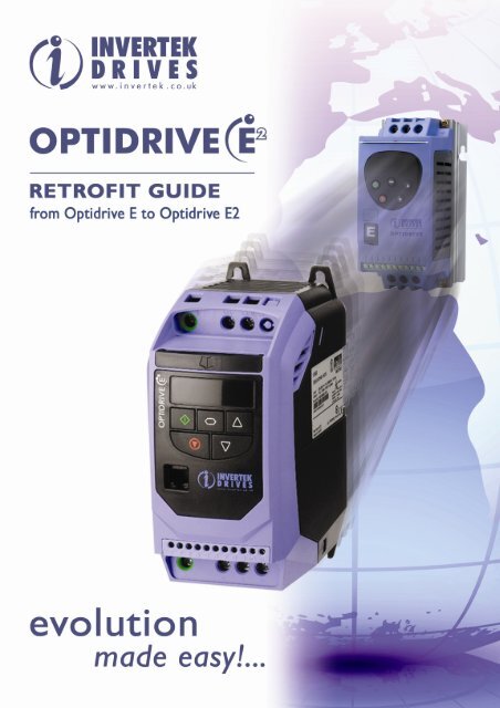
<strong>Optidrive</strong> E to <strong>Optidrive</strong> <strong>E2</strong> Retrofit GuideInvertek Drives Ltd is dedicated to the design,manufacture and marketing of variable speed drives forcontrol of electric motors.The company’s products are sold globally by a networkof specialist distributors in over 60 countries. InvertekDrives unique and innovative <strong>Optidrive</strong> range is designedfor ease of use and meets with recognised designstan<strong>da</strong>rds for CE (Europe), cUL (North America) andCTICK (Australia).Rich in features the <strong>Optidrive</strong> <strong>E2</strong> is the latest and mostcommercially competitive <strong>Optidrive</strong> in the <strong>Optidrive</strong>family.Innovative and compact the <strong>Optidrive</strong> <strong>E2</strong> rangecombines good looks with robustness, reliability andeasy to use performance.This guide has <strong>be</strong>en produced to provide you with aneasy way of retrofitting existing <strong>Optidrive</strong> E drives withthe <strong>Optidrive</strong> <strong>E2</strong>.TABLE OF CONTENTSSECTIONPAGE1. SPECIFICATION COMPARISON...................................................................... 32. RATING COMPARISONS................................................................................... 43. MECHANICAL INSTALLATION COMPARISONS ........................................ 64. POWER WIRING COMPARISONS................................................................... 95. CONTROL WIRING COMPARISONS............................................................ 126. PARAMETER COMPARISONS ........................................................................ 137. ANALOG AND DIGITAL INPUT CONFIGURATIONS .............................. 1685-RET<strong>E2</strong>-00 <strong>Optidrive</strong> <strong>E2</strong> Retrofit Guide Issue 1.00, January 2008Invertek Drives Ltd adopts a policy of continuous improvement and whilst every effort has <strong>be</strong>en made to provide accurateand up to <strong>da</strong>te information, the information contained in this brochure should <strong>be</strong> used for gui<strong>da</strong>nce purposes only and doesnot form the part of any contract.2 <strong>Optidrive</strong> <strong>E2</strong> Retrofit Guidewww.invertek.co.uk
Output ratingsInput RatingsAmbientConditionsProgramming1. Specification Comparison<strong>Optidrive</strong> E<strong>Optidrive</strong> <strong>E2</strong>Overload Capacity150% for 60 seconds 150% for 60 seconds175% for 2 seconds 175% for 2 secondsFrequency 0…500Hz 0…500HzFrequency 48 - 62Hz 48 - 62Hz110 - 115 + / - 10% 1-Phase ( 0.5 - 1.5HP) 110 - 115 + / - 10% 1-Phase ( 0.5 - 1.5HP)220 - 240 + / - 10% 1-Phase200 - 240 + / - 10% 1-Phase(0.37 - 2.2kW / 0.5 - 3HP)(0.37 - 2.2kW / 0.5 - 3HP)Voltage200 - 240 + / - 10% 3-PhaseN/A(0.37 - 3.7kW / 0.5 - 5HP)380 - 480 + / - 10% 3-Phase380 - 480 + / - 10% 3-Phase(0.75 - 4kW / 1 – 5HP)(0.75 - 7.5kW / 1 - 10HP)TemperatureOperating : 0 to 50°C Max;Operating : 0 to 50°C Max;Storage : -40 to +60°CStorage : -40 to +60°CAltitude 0 - 2000m, derate 1% per 100m above 1000m 0 - 2000m, derate 1% per 100m above 1000mIngress Protection IP20 & Optional IP55 IP20 & Optional IP55Keypad Yes YesPDA N/A YesSmartphone N/A YesControlSpecificationProgrammableI/OKeypad DisplayProtectiveFunctionsBuscommunicationControl Method V/F Voltage VectorPWM Frequency 4…32kHz (effective) 4…32kHz (effective)V/Hz ratio Linear / Variable LinearBoost Yes YesStop Mode Coast / Ramp / DC Brake Coast / Ramp / DC BrakeInternal Brake transistor N/A Yes (Sizes 2 and 3). External Resistor requiredCapacity N/A 100% Drive Rated Power continuouslySkip Frequency One point, adjustable frequency band One point, adjustable frequency band0…10 VDC 0…10 VDC4…20mA4…20mAFrequency set point0…20mA0…20mAcontrol20…4mA20…4mADigital - KeypadDigital - KeypadN/AMODBUSPre-set speeds 4 4PI Control N/A YesSpin Start N/A YesAcceleration 0..3000 sec 0..600 secDeceleration (2 ramps) 0..3000 sec (2 ramps) 0..25 secInput 1 Programmable Digital Input Programmable Digital InputInput 2 Programmable Digital Input Programmable Digital InputInput 3 Programmable Digital Input User Selectable Analog / Digital InputInput 4 User Selectable Analog / Digital Input User Selectable Analog / Digital InputOutput 1 Programmable Analog / Digital Output Programmable Analog / Digital OutputRelay 1 Relay Output (30 VDC 5A, 250 VAC, 6A) Relay Output (30 VDC 5A, 250 VAC, 6A)Operating Display6-digit LED showing:Output Frequency, Current, Rpm6-digit LED showing:Output Frequency, Current, Rpm, and UserScalable valuesRemote mount N/A Optional Optiport <strong>E2</strong> remote mounting keypadOver voltageOver voltageOver currentOver currentUnder voltageUnder voltageExternal tripExternal tripInverter TripMotor overloadMotor overloadOver temperatureOver temperatureUnder temperatureUnder temperatureShort circuitedShort circuitedN/APhase LossMemory Last 4 Trips stored Last 4 Trips storedMODBUS RTU N/A Stan<strong>da</strong>rdProfibus DP N/A via GatewayDeviceNet N/A via GatewayRS485 (Optibus) N/A Stan<strong>da</strong>rd<strong>Optidrive</strong> <strong>E2</strong> Retrofit Guide 3www.invertek.co.uk
2. Rating Comparisons2.1. Identifying the E drive by model num<strong>be</strong>r2.2. <strong>Optidrive</strong> E model num<strong>be</strong>rs110-115V ±10% - 1 Phase Input - 3 Phase 230V Output (Voltage Doubler)kW Model Num<strong>be</strong>rHP Model Num<strong>be</strong>rkWWith Filter Without FilterWith Filter Without FilterHP Output Current (A) Frame SizeODEF-11005-USA ODE-11005-USA 0.5 2.3 1ODEF-11010-USA ODE-11010-USA 1 4.3 1ODEF-21015-USA ODE-21015-USA 1.5 5.8 2200-240V ±10% - 1 Phase InputkW Model Num<strong>be</strong>rHP Model Num<strong>be</strong>rkWWith Filter Without FilterWith Filter Without FilterHP Output Current (A) Frame SizeODEF-12037-IN ODE-12037-IN 0.37 ODEF-12005-USA ODE-12005-USA 0.5 2.3 1ODEF-12075-IN ODE-12075-IN 0.75 ODEF-12010-USA ODE-12010-USA 1 4.3 1ODEF-12150-IN ODE-12150-IN 1.5 ODEF-12020-USA ODE-12020-USA 2 7 1ODEF-22220-IN ODE-22220-IN 2.2 ODEF-22030-USA ODE-22030-USA 3 10.5 2380-480V ±10% - 3 Phase InputkW Model Num<strong>be</strong>rHP Model Num<strong>be</strong>rkWWith Filter Without FilterWith Filter Without FilterHP Output Current (A) Frame SizeODEF-14075-IN ODE-14075-IN 0.75 ODEF-14010-USA ODE-14010-USA 1 2.2 1ODEF-14150-IN ODE-14150-IN 1.5 ODEF-14020-USA ODE-14020-USA 2 4.1 1ODEF-24220-IN ODE-24220-IN 2.2 ODEF-24030-USA ODE-24030-USA 3 5.8 2ODEF-24400-IN ODE-24400-IN 4 ODEF-24050-USA ODE-24050-USA 5 9.5 24 <strong>Optidrive</strong> <strong>E2</strong> Retrofit Guidewww.invertek.co.uk
2.3. Identifying the <strong>E2</strong> drive by model num<strong>be</strong>rEach drive can <strong>be</strong> identified by its model num<strong>be</strong>r, as shown in Figure 1 Drive Model Num<strong>be</strong>r Format. The model num<strong>be</strong>r ison the shipping la<strong>be</strong>l and the drive nameplate. The model num<strong>be</strong>r includes the drive and any options.Figure 1 Drive Model Num<strong>be</strong>r Format2.4. Drive model num<strong>be</strong>rs110-115V ±10% - 1 Phase Input - 3 Phase 230V Output (Voltage Doubler)With FilterkW Model Num<strong>be</strong>rWithout Filter200-240V ±10% - 1 Phase InputWith FilterkW Model Num<strong>be</strong>rWithout FilterkWkWWith FilterWith FilterHP Model Num<strong>be</strong>rHP Model Num<strong>be</strong>rWithout FilterHPOutput Current(A)FrameSizeODE-2-11005-1H01* 0.5 2.3 1ODE-2-11010-1H01* 1 4.3 1ODE-2-21015-1H04* 1.5 5.8 2Without FilterHPOutput Current(A)ODE-2-12037-1KB1* ODE-2-12037-1K01* 0.37 ODE-2-12005-1HB1* ODE-2-12005-1H01* 0.5 2.3 1ODE-2-12075-1KB1* ODE-2-12075-1K01* 0.75 ODE-2-12010-1HB1* ODE-2-12010-1H01* 1 4.3 1ODE-2-12150-1KB1* ODE-2-12150-1K01* 1.5 ODE-2-12020-1HB1* ODE-2-12020-1H01* 2 7 1ODE-2-22150-1KB4* ODE-2-22150-1K04* 1.5 ODE-2-22020-1HB4* ODE-2-22020-1H04* 2 7 2ODE-2-22220-1KB4* ODE-2-22220-1K04* 2.2 ODE-2-22030-1HB4* ODE-2-22030-1H04* 3 10.5 2200-240V ±10% - 3 Phase InputWith FilterkW Model Num<strong>be</strong>rWithout FilterkWWith FilterHP Model Num<strong>be</strong>rWithout FilterHPOutput Current(A)ODE-2-12037-3K01* 0.37 ODE-2-12005-3H01* 0.5 2.3 1ODE-2-12075-3K01* 0.75 ODE-2-12010-3H01* 1 4.3 1ODE-2-12150-3K01* 1.5 ODE-2-12020-3H01* 2 7 1ODE-2-22150-3KB4* ODE-2-22150-3K04* 1.5 ODE-2-22020-3HB4* ODE-2-22020-3H04* 2 7 2ODE-2-22220-3KB4* ODE-2-22220-3K04* 2.2 ODE-2-22030-3HB4* ODE-2-22030-3H04* 3 10.5 2ODE-2-32040-3KB4* ODE-2-32040-3K04* 4.0 ODE-2-32050-3HB4* ODE-2-32050-3H04* 5 18 3380-480V ±10% - 3 Phase InputWith FilterkW Model Num<strong>be</strong>rWithout FilterkWWith FilterHP Model Num<strong>be</strong>rWithout FilterHPOutput Current(A)ODE-2-14075-3KA1* ODE-2-14075-3K01* 0.75 ODE-2-14010-3HA1* ODE-2-14010-3H01* 1 2.2 1ODE-2-14150-3KA1* ODE-2-14150-3K01* 1.5 ODE-2-14020-3HA1* ODE-2-14020-3H01* 2 4.1 1ODE-2-24150-3KA4* ODE-2-24150-3K04* 1.5 ODE-2-24020-3HA4* ODE-2-24020-3H04* 2 4.1 2ODE-2-24220-3KA4* ODE-2-24220-3K04* 2.2 ODE-2-24030-3HA4* ODE-2-24030-3H04* 3 5.8 2ODE-2-24400-3KA4* ODE-2-24400-3K04* 4 ODE-2-24050-3HA4* ODE-2-24050-3H04* 5 9.5 2ODE-2-34055-3KA4* ODE-2-34055-3K04* 5.5 ODE-2-34075-3HA4* ODE-2-34075-3H04* 7.5 14 3ODE-2-34075-3KA4* ODE-2-34075-3K04* 7.5 ODE-2-34100-3HA4* ODE-2-34100-3H04* 10 18 3Note: * is to <strong>be</strong> substituted for the appropriate IP/NEMA rated product.FrameSizeFrameSizeFrameSize<strong>Optidrive</strong> <strong>E2</strong> Retrofit Guide 5www.invertek.co.uk
3. Mechanical Installation Comparisons3.1. Hole mounting dimensionsThe diagrams <strong>be</strong>low can <strong>be</strong> used to retrofit an <strong>Optidrive</strong> <strong>E2</strong> into an existing enclosure for an <strong>Optidrive</strong> E.Key:<strong>Optidrive</strong> E<strong>Optidrive</strong> <strong>E2</strong>_ _ _ _ _ _ ___________Size 2 Size 1Drive D H K L MSize mm in mm in mm in mm in mm in1 162 6.38 50 1.97 11 0.43 32 1.26 25 0.982 209 8.23 63 2.48 15 0.59 4 0.15 - -6 <strong>Optidrive</strong> <strong>E2</strong> Retrofit Guidewww.invertek.co.uk
3.2. <strong>Optidrive</strong> <strong>E2</strong> - IP20 mechanical dimensions and mountingDrive A B C D E F G H I ∅ J ∅Size mm in mm in mm in mm in mm in mm in mm in mm in mm in mm in1 173 6.81 160 6.30 109 4.29 162 6.38 5 0.20 123 4.84 82 3.23 50 1.97 5.5 0.22 10 0.392 221 8.70 207 8.15 137 5.39 209 8.23 5.3 0.21 150 5.91 109 4.29 63 2.48 5.5 0.22 10 0.393 261 10.28 246 9.69 - - 247 9.72 6 0.24 175 6.89 131 5.16 80 3.15 5.5 0.22 10 0.39Size 1 & 2 drives are designed to <strong>be</strong> mounted onto DIN rail.TerminalsControlPowerTorque Settings0.5 Nm1 Nm<strong>Optidrive</strong> <strong>E2</strong> Retrofit Guide 7www.invertek.co.uk
4. Power Wiring Comparisons4.1. <strong>Optidrive</strong> E IP20 Connection Diagram4.2. <strong>Optidrive</strong> <strong>E2</strong> IP20 Connection Diagram<strong>Optidrive</strong> <strong>E2</strong> Retrofit Guide 9www.invertek.co.uk
4.3. <strong>Optidrive</strong> E IP55 / NEMA 12 Switched Connection Diagram4.4. <strong>Optidrive</strong> <strong>E2</strong> IP55 / NEMA 12 Switched Connection Diagram10 <strong>Optidrive</strong> <strong>E2</strong> Retrofit Guidewww.invertek.co.uk
4.5. Braking Transistor ConnectionsThe <strong>Optidrive</strong> E does not have a dynamic braketransistor in the drive.The <strong>Optidrive</strong> <strong>E2</strong> has a dynamic brake transistor on allSize 2 and 3 ratings. For these drives an externalbraking resistor will need <strong>be</strong> connected to +DC and BR.For Invertek brake resistors the <strong>Optidrive</strong> softwareprotects the Optibrake from overload, hence no needfor expensive overload relays are required (P-34=1)Internal fusible element ensures fail safe operation4.6. DC BUS ConnectionsThe <strong>Optidrive</strong> E does not have DC bus connections.On the <strong>Optidrive</strong> <strong>E2</strong> IP20, sizes 2 & 3 provision has <strong>be</strong>enmade for ±DC connections. This provides the ability tooperate on parallel DC Bus systems where typically themotor/regenerative energy is transferred <strong>be</strong>tween thedrives.Further information can <strong>be</strong> found in the Advanced UserGuide.For non-Invertek approved resistors orapplication requiring higher braking powersexternal thermal/overload protection for theresistor is required<strong>Optidrive</strong> <strong>E2</strong> Retrofit Guide 11www.invertek.co.uk
5. Control Wiring Comparisons5.1. Control terminal connections<strong>Optidrive</strong> E<strong>Optidrive</strong> <strong>E2</strong>Terminal Default Connections Signal Default Connections Signal1 +10V User Output, +24V User Output,2 Digital Input 1 Digital Input 13 Digital Input 2 Digital Input 24 Digital Input 3Digital Input 3 /Analog Input 25 +10V User Output +10V User Output6Analog Input 1 /Digital Input 4Analog Input 1 /Digital Input 47 0V 0V8Analog Output /Digital OutputAnalog Output /Digital Output9 0V 0V10 Relay Common Relay Common11 Relay NO Contact Relay NO ContactAll digital inputs are positive logic.<strong>Optidrive</strong> E<strong>Optidrive</strong> <strong>E2</strong>Control Terminal 1 +10V User Output +24V User OutputCurrent Limit 25mA 100mAControl Terminal 2 & 3 Digital Inputs 1 & 2Digital Voltage Range 8 to 30V 8 to 30VControl Terminal 4 Digital Input 3 Digital Input 3 or Analog Input 2Digital Voltage Range 8 to 30V 8 to 30VAnalog Input formats N/A As per Parameter P=47Voltage: 0-10VCurrent: 4-20mA, 0-20mA, 20-4mAControl Terminal 5+10V OutputCurrent Limit 10mA 10mAMinimum Resistance 500Ω 1kΩControl Terminal 6 Analog Input 1 or Digital Input 4Analog Input formats As per Parameter P=16Voltage: 0-10V, 10V-0Current: 4-20mA, 0-20mA, 20-4mAAs per Parameter P=16Voltage: 0..10V, b 0..10V,Current: 0..20mA,t 4..20mA, r 4..20mA,t 20..4mA r 20..4mADigital Voltage Range 8 to 30V 8 to 30VControl Terminal 7 & 90VControl Terminal 8Analog Output or Digital OutputAnalog Voltage Range 0 to 10V 0 to 10VDigital Voltage Range 0 to 10V 0 to 24VMax Output Current 20mA 20mAControl Terminal 10 & 11User Relay ContactsVoltage Rating 250 Vac / 30Vdc 250 Vac / 30VdcCurrent Rating 6A / 5A 6A / 5AContact Isolation 2.5kV 2.5kVOperation of RelayOPEN:No AC Supply OR Function of P-18 disabledCLOSED:AC Supply present & Function of P-18 enabled.OPEN:No AC Supply OR Function of P-18 disabledCLOSED:AC Supply present & Function of P-18 enabled.12 <strong>Optidrive</strong> <strong>E2</strong> Retrofit Guidewww.invertek.co.uk
6. Parameter Comparisons6.1. Stan<strong>da</strong>rd parameters comparison<strong>Optidrive</strong> E<strong>Optidrive</strong> <strong>E2</strong>Par.DefaultDefaultDescriptionDescriptionSettingSettingP-01 Maximum speed 50Hz Maximum speed 50Hz (60Hz)P-02 Minimum speed 0Hz Minimum speed 0HzP-03 Acceleration ramp time 5s Acceleration ramp time 5sP-04 Deceleration ramp time 5s Deceleration ramp time 5sP-05 Stop mode select 0 Stop mode select 0P-06 V/F Characteristic 0 Energy Optimiser 0P-07 Fast Stop (2nd decel ramp time) 0.0s Motor rated voltage230V400V (460V)P-08 Motor rated current Drive rating Motor rated current Drive ratingP-09 Motor rated frequency 50 Hz Motor rated frequency 50Hz (60Hz)P-10 Motor rated speed 0 Motor rated speed 0P-11 Voltage boost 3% Voltage boostP-12Terminal / KeypadDrive Control Mode Selection0Terminal / Keypad /MODBUS / PIDrive Control Mode SelectionMotor powerdependentP-13 Trip log Read only Trip log Read onlyP-14 Extended menu access 0 Extended menu access 00NOTENOTEDefault parameter values for Horse Power rated drives are shown in bracketsStandby mode is enabled automatically when the drive is at zero speed for > 20 seconds6.2. P-00 Read Only Drive Status Parameters<strong>Optidrive</strong> E<strong>Optidrive</strong> <strong>E2</strong>P00-01 Unscaled analog input (%) 1st Analog input valueP00-02 Speed ref. via scaled analog input 2nd Analog input value(Hz)P00-03 Pre-ramp speed ref. (Hz) Speed reference inputP00-04 Post-ramp speed ref. (Hz) Digital input statusP00-05 Not used ReservedP00-06 Stator field frequency (Hz) ReservedP00-07 Applied motor voltage (V) Applied motor voltageP00-08 DC bus voltage (V) DC bus voltageP00-09 Internal thermistor (NTC) value Internal Heatsink temperatureP00-10 Hours run meterP00-11 Run time since last trip (1)P00-12 Run time since last trip (2)P00-13 Run time since last disableP00-14 Drive Effective SwitchingFrequencyP00-15 DC bus voltage logP00-16 Thermistor temperature logP00-17 Motor currentP00-18 Software ID, I/O processor &motor controlP00-19 Drive serial num<strong>be</strong>rP00-20 Drive identifier<strong>Optidrive</strong> <strong>E2</strong> Retrofit Guide 13www.invertek.co.uk
6.3. Extended parameter comparison<strong>Optidrive</strong> E<strong>Optidrive</strong> <strong>E2</strong>DefaultDefaultPar. DescriptionDescriptionSettingSettingP-15 Motor rated voltage 0V Digital input function select 0P-16 Analog input format (V / mA) 0-10V Analog input format 0..10VP-17 Effective Power stage Switching frequency 16 kHz Effective switching frequency 8 / 16kHzP-18 Relay output function1 : (Drivehealthy)User relay output select 1P-19 Digital inputs function select 0 User relay output limit 100%P-20 Preset / Jog speed 1 50Hz Preset speed 1 0 HzP-21 Preset / Jog speed 2 0 Hz Preset speed 2 0 HzP-22 Preset / Jog speed 3 0 Hz Preset speed 3 0 HzP-23 Preset / Jog speed 4 0 Hz Preset speed 4 0 HzP-24 Not used2nd decel ramp time(Fast Stop)0P-25Analog output function 0Analog output function select 8P-26 V/F characteristic adjustment factor 100% Skip frequency hysteresis band 0 HzP-27 Skip freq / speed 0 Hz Skip frequency 0 HzP-28 Skip freq / speed band 0 Hz V/F characteristic adjustment voltage 0P-29 V/F characteristic adjustment frequency 0 Hz V/F characteristic adjustment frequency 0.0HzP-30 Drive start mode Auto-0 Terminal mode restart function Auto-0P-31 DC injection voltage 10% Keypad mode restart function 1P-32 DC injection braking time 0s DC injection on stop0(disabled)P-33P-34 Not usedP-35DC injection on enableSpeed reference scaling factor (analog ordigital)P-36 Not used0Spin Start (S2 & S3 only)DC injection on start (S1)Brake chopper enable(not S1)100% Analog input scaling 100%Serial Communications addressMODBUS enable / baudrate selectTrip enable / delay0010P-buSt 3000(3 secondtrip)P-37 Access code definition 101 Access code definition 101P-38 Parameter access lock 0 Parameter access lock 0P-39 Hours run meter Read only Analog input offset 0%P-40 Drive identifier Read only Display speed scaling factor 0.000P-41 N/A User PI Proportional Gain 1.0P-42 N/A User PI Integral time constant 1.0sP-43 N/A User PI operating mode 0P-44 N/A User PI reference select 0P-45 N/A User PI digital reference 0.0 %P-46 N/A User PI feedback select 0P-47 N/A 2nd analog input format 0 ..10V14 <strong>Optidrive</strong> <strong>E2</strong> Retrofit Guidewww.invertek.co.uk
6.4. Adjusting the Voltage / Frequency (V/f) characteristics<strong>Optidrive</strong> E<strong>Optidrive</strong> <strong>E2</strong>VoltageP-15P-06 = 0,Constant Torque, INDUSTRIALDefaultAdjustedP-15/2P-26P-11BoostP-09/2 P-29P-09 P-01Frequency6.5. P-06 - HVAC to Energy Optimiser<strong>Optidrive</strong> E<strong>Optidrive</strong> <strong>E2</strong>VoltageP-15P-06 = 1 Fan/ Pump, HVACDefaultAdjustedP-26P-11BoostP-29P-09 P-01FrequencyParameter P-06 can <strong>be</strong> adjusted depending upon the type of application the drive is to <strong>be</strong> configured for.The default setting is for constant torque applications.For applications requiring energy saving, typically HVAC and pumping, the energy optimiser (P-06) parameter can <strong>be</strong>enabled. The drive automatically reduces the applied motor voltage (hence torque) depending on the load conditions.The advantage of this control over a variable torque characteristic traditionally used on the Optyidrive E, is that a higherstarting torque can <strong>be</strong> achieved.<strong>Optidrive</strong> <strong>E2</strong> Retrofit Guide 15www.invertek.co.uk
7. Analog and Digital Input Configurations7.1. <strong>Optidrive</strong> E - Terminal mode (P-12 =0)P-19 Input 1 function Input 2 function Input 3 function Additional Information0123456789101112Open: Stop (disable)Closed: Run (enable)Open: Stop (disable)Closed: Run (enable)Open: Stop (disable)Closed: Run (enable)Open: Stop (disable)Closed: Run (enable)Open: Stop (disable)Closed: Run (enable)Open: Fwd Stop (disable)Closed: Fwd Run (enable)Open: Stop (disable)Closed: Run (enable)Open: Fwd Stop (disable)Closed: Fwd Run (enable)Open: Stop (disable)Closed: Run (enable)Open: Fwd Stop (disable)Closed: Fwd Run (enable)Normally Open (N.O.)Momentary close to run fwdNormally Open (N.O.)Momentary close to run fwdOpen: Stop (disable)Closed: Run (enable)Open: Analog speed referenceClosed: Preset / Jog Speed 1Open: Analog speed referenceClosed: Preset / Jog Speed 1 or 2,selected by Digital Input 3Open: Voltage analog inputClosed: Current analog inputOpen: Preset / Jog Speed 1Closed: Preset / Jog Speed 2Digital Input 2 Open + Digital Input 3 Open = Preset / Jog Speed 1Digital Input 2 Closed + Digital Input 3 Open = Preset / Jog Speed 2Digital Input 2 Open + Digital Input 3 Closed = Preset / Jog Speed 3Digital Input 2 Closed + Digital Input 3 Closed = Preset / Jog Speed 4External trip input :Open: TRIP; Closed: no trip.Open: Run forwardClosed: Run reverseOpen: Reverse Stop (disable)Closed: Reverse Run (enable)Open: Run forwardClosed: Run reverseOpen: Reverse Stop (disable)Closed: Reverse Run (enable)Open: Run forwardClosed: Run reverseOpen: Reverse Stop (disable)Closed: Reverse Run (enable)Normally Closed (N.C.)Momentary open to Stop (disable)Normally Closed (N.C.)Momentary open to Stop (disable)Close to runOpen to activate fast stop (P-07)Open: Analog speed referenceClosed: Preset / Jog Speed 1Open: Analog speed referenceClosed: Preset / Jog Speed 1Open: Analog speed referenceClosed: Preset / Jog Speed 1External trip input :Open: TRIP; Closed: no trip.External trip input :Open: TRIP; Closed: no trip.Open: Preset / Jog Speed 1Closed: Preset / Jog Speed 2Open: Preset / Jog Speed 1Closed: Preset / Jog Speed 2Open: Analog speed referenceClosed: Preset / Jog Speed 1Normally Open (N.O.)Momentary close to run reverseOpen: Analog speed referenceClosed: Preset / Jog Speed 1The format of the current analoginput is defined by P-16, if P-16 isset to 0-10V a 4-20mA formatwill <strong>be</strong> assumed when input 3closedAnalog voltage input used as 4thdigital input: if5V
7.3. <strong>Optidrive</strong> <strong>E2</strong> - Terminal mode (P-12 =0)P-15 Digital input 1 (T1) Digital input 2 (T2) Digital input 3 (T4) Analog input (T6) Comments0Open: Stop (disable) Open : Forward run Open : Analog speed refClosed: Run (enable) Closed : Reverse run Closed : Preset speed 1Analog input 1 reference1Open: Stop (disable) Open: Analog speed ref Open: Preset speed 1Closed: Run (enable) Closed:Preset speed 1/2 Closed:Preset speed 2Analog input 1 reference2Open: Stop (disable)Closed: Run (enable)3 1) Open: Stop (disable)Closed: Run (enable)45Open: Stop (disable)Closed: Run (enable)Open: Fwd StopClosed: Fwd Run6 1) Open: Stop (disable)Closed: Run (enable)789101112Open: Stop (disable)Closed: Fwd Run (enable)Open: Stop (disable)Closed: Run (enable)Open: Stop (disable)Closed: Forward Run (enable)Normally Open (NO)Momentary close to runNormally Open (NO)Momentary close to runOpen: Stop (disable)Closed: Run (enable)Digital Input 2 Digital Input 3 Preset SpeedOpen Open Preset Speed 1Closed Open Preset Speed 2Open Closed Preset Speed 3Closed Closed Preset Speed 4Open : Analog speed refClosed : Preset speed 1Open : Analog input 1Closed : Analog input 2Open: Reverse StopClosed: Reverse RunOpen : ForwardClosed : ReverseOpen: Stop (disable)Closed: Rev Run (enable)Open : ForwardClosed : ReverseOpen: Stop (disable)Closed: Reverse Run(enable)Normally Closed (NC)Momentary open to stopNormally Closed (NC)Momentary open to stopOpen: Fast Stop (disable)Closed: Run (enable)External trip input :Open: Trip,Closed: RunOpen: Preset speeds 1-4Closed:Max Speed(P-01Analog input 1 referenceAnalog input 2 reference Analog input 1 referenceOpen : Analog speed refClosed : Preset speed 1Analog input 1 referenceExternal trip input :Open: Trip,Analog input 1 referenceClosed: RunExternal trip input :Open: Trip,Analog input 1 referenceClosed: RunDigital Input 2 Analog Input 1 Preset SpeedOpen Open Preset Speed 1Closed Open Preset Speed 2Open Closed Preset Speed 3Closed Closed Preset Speed 4Digital Input 2 Analog Input 1 Preset SpeedOpen Open Preset Speed 1Closed Open Preset Speed 2Open Closed Preset Speed 3Closed Closed Preset Speed 4Open : Analog speed refClosed:Preset speed 1Analog input 1 referenceNormally Open (NO)Momentary close to revOpen : Analog speed refClosed : Preset speed 1Analog input 1 referenceAnalog input 1 reference4 Preset speeds selectable.Analog input used as digitalinput Closed status: 8V < Vin< 30VConnect external thermistortype PT100 or similar todigital input 3Switches <strong>be</strong>tween analoginputs 1 and 2Closing digital inputs 1 and 2together carries out a faststop (P-24)Connect external thermistortype PT100 or similar todigital input 3Closing digital inputs 1 and 2together carries out a faststop (P-24)Closing digital inputs 1 and 2together carries out a faststop (P-24)Closing digital inputs 1 and 3together carries out a faststop (P-24)7.4. <strong>Optidrive</strong> <strong>E2</strong> - Keypad mode (P-12 = 1 or 2)P-15 Digital input 1 (T1) Digital input 2 (T2) Digital input 3 (T4) Analog input (T6) Comments0, 1,Open: Stop (disable) Closed : remote UP pushbuttonpush-button+24V : ReverseClosed : remote DOWN Open : Forward5,Closed: Run (enable)8..122Open: Stop (disable)Closed: Run (enable)3 1) Open: Stop (disable)Closed: Run (enable)4Open: Stop (disable)Closed: Run (enable)6 1) Open: Stop (disable)Closed: Run (enable)7Open: Forward StopClosed: Forward RunClosed : remote UP pushbuttonClosed : remote UP pushbuttonClosed : remote UP pushbuttonOpen : Forward runClosed : Reverse runOpen: Reverse StopClosed: Reverse RunClosed : remote DOWNpush-buttonExternal trip input :Open: Trip, Closed: RunOpen : Keypad speed refClosed : Analog input 1External trip input :Open: Trip, Closed: RunExternal trip input :Open: Trip, Closed: RunOpen : Keypad speed ref+24V : Preset speed 1Closed : remote DOWNpush-buttonAnalog input 1Open : Keypad speed ref+24V : Preset speed 1Open : Keypad speed ref+24V : Preset speed 1Connect external thermistortype PT100 or similar todigital input 3Connect external thermistortype PT100 or similar todigital input 3Closing digital inputs 1 and 2together carries out a faststop (P-24)NOTEBy default if the enable signal is present the drive will not Enable until the START button is pressed. To automatically enablethe drive when the enable signal is present set P-31 = 2 or 3. This then disables the use of the START & STOP buttons<strong>Optidrive</strong> <strong>E2</strong> Retrofit Guide 17www.invertek.co.uk
7.5. MODBUS control mode (P12 = 3 or 4)MODBUS control is not possible on <strong>Optidrive</strong> E.P-15 Digital input 1 (T1) Digital input 2 (T2) Digital input 3 (T4) Analog input (T6) Comments0..2,4..5,8..12Open: Stop (disable)Closed: Run (enable)3 1) Open: Stop (disable)Closed: Run (enable)6 1) Open: Stop (disable)Closed: Run (enable)7 1) Open: Stop (disable)Closed: Run (enable)No effect No effect No effectOpen : Master speed refClosed : Preset speed 1Open : Master speed refClosed : Analog inputOpen : Master speed refClosed : keypad speed refExternal trip input :Open: Trip, Closed: RunExternal trip input :Open: Trip, Closed: RunExternal trip input :Open: Trip, Closed: RunNo effectAnalog input referenceNo effectRun and stop commandsgiven via the RS485 link andDigital input 1 must <strong>be</strong>closed for the drive to run.Connect external thermistortype PT100 or similar todigital input 3Master Speed Ref - start andstop controlled via RS485.Keypad Speed Ref - driveauto runs if digital input 1closed, depending on P-31setting7.6. User PI control mode (P-12 = 5)User feedback PI control is not possible on <strong>Optidrive</strong> E.For feedback applications such as pressure, temperature. & flow the <strong>Optidrive</strong> <strong>E2</strong> has an in built PI feedback controller.The digital input s on the drive can then <strong>be</strong> programmed to suit the application using the functions of P-15.P-15 Digital input 1 (T1) Digital input 2 (T2) Digital input 3 (T4) Analog input (T6) Comments0, 2,Open: Stop (disable) Open : PI control4..5,PI feedback analog input No effectClosed: Run (enable) Closed : Preset speed 18..121Open: Stop (disable)Closed: Run (enable)3, 6, Open: Stop (disable)7 1) Closed: Run (enable)Open : PI controlClosed : Analog input 1Open : PI controlClosed : Preset speed 1PI feedback analog input Analog input 1External trip input :Open: Trip, Closed: RunPI feedback analog inputConnect external thermistortype PT100 or similar todigital input 3NOTEBy default the PI reference is set for a digital reference level set in P-45.When using an Analog reference set P-44 = 1 (analog) and connect reference signal to analog input 1 (T6).The default settings for proportional gain (P-41), integral gain (P-42) and feedback mode (P-43) are suitable for most HVACand pumping applications.The analog reference used for PI controller can also <strong>be</strong> used as the local speed reference when P15=1.18 <strong>Optidrive</strong> <strong>E2</strong> Retrofit Guidewww.invertek.co.uk
7.7. External trip & Motor thermistor inputThe <strong>Optidrive</strong> E has the provision for a normally closedExternal trip (Emergency-Stop) input to the drive. Thistrips the drive on E-trip if the contact is opened.In addition to the same function on <strong>Optidrive</strong> <strong>E2</strong> it ispossible to connect the internal motor thermistordirectly to the drive. If the motor temperature isexcessive the drive will trip on E-trip to protect it. Theinput is suitable for PTC motor thermistors of typePT100 or similar.Notes:<strong>Optidrive</strong> <strong>E2</strong> Retrofit Guide 19www.invertek.co.uk
11. 0. Drive Protection20 <strong>Optidrive</strong> <strong>E2</strong> Retrofit Guidewww.invertek.co.uk