
Create successful ePaper yourself
Turn your PDF publications into a flip-book with our unique Google optimized e-Paper software.
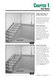
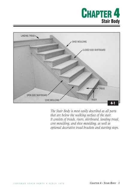
CHAPTER 4Stair BodyLANDING TREADSHOE MOULDINGCLOSED SIDE SKIRTBOARDTREADOPEN SIDE SKIRTBOARDCOVE MOULDINGRISER4-1The Stair Body is most easily described as all partsthat are below the walking surface of the stair.It consists of treads, risers, skirtboard, landing tread,cove moulding, and shoe moulding, as well asoptional decorative tread brackets and starting steps.C O F F M A N S T A I R P A R T S • S I N C E 1 8 7 4CHAPTER 4 - <strong>STAIR</strong> <strong>BODY</strong> 1
SKIRTBOARDSBoth closed side and open side skirtboard layout can be marked with the use of angle gaugesand a framing square (See <strong>Chapter</strong> 3, Page 6). Begin by marking out the necessary number ofrise and run dimensions for your stair.FIRST FLOOR CUTRISE AND RUN DIMENSIONSBOTTOM EDGE4-2CLOSED SIDE SKIRTBOARD LAYOUTAt the bottom of a closed side skirtboard, use a framing square to extend a line from thebottom of the first rise parallel to the tread lines above. This will be the first floor cut.PHOTO 4-2.NOTE: If the first rise on the rough carriage was adjusted for the thickness of the finishedfloor materials (See Photo 3-14), you must make the same adjustment to the first rise ofthe skirtboard.LAST RUNCLOSED SIDE WALL CUTBOTTOM EDGE4-3At the top of the closed side skirtboard extend the last riser line (representing the second floorheader) across the board. This mark will be your second floor closed side wall cut.PHOTO 4-3.2 CHAPTER 4 - <strong>STAIR</strong> <strong>BODY</strong>C O F F M A N S T A I R P A R T S • S I N C E 1 8 7 4
WALL CUT MEASUREMENTMeasure the distance fromthe top of the spacer behindthe rough carriage (See Photo3-23) to the top of thesecond floor subfloor.PHOTO 4-4.SECOND FLOOR SUBFLOORRULER SITTING ON SPACERINSIDE ROUGH CARRIAGE4-4LAST RUNWALL CUTSECOND FLOOR CUTTransfer this measurementto the extended top riserline and use the framingsquare to extend the lineparallel to the tread linesbelow it. This will be yoursecond floor cut (SeePhoto 4-13). PHOTO 4-5.CHECK MEASUREMENT THROUGHOUT <strong>STAIR</strong>TO ASSURE EVEN SKIRTBOARD EXPOSUREC O F F M A N S T A I R P A R T S • S I N C E 1 8 7 4 CHAPTER 4 - <strong>STAIR</strong> <strong>BODY</strong> 34-54-6After making the first floorcut, wall cut, and secondfloor cut, place theskirtboard between thesheetrock and the roughcarriage. NOTE: Sawtoothcuts are not necessarythrough the length of theskirtboard when a spacerhas been installed betweenthe stud wall and thecarriage (See Photo 3-23).Check to make sure that thefloor and wall cuts areaccurate and that theamount of skirtboard shownabove the rough carriage isequal from the top of thestair to the bottom.PHOTO 4-6.
To finish the closed sideskirtboard, mark and cut thebottom to tie into the firstfloor base moulding.PHOTO 4-7.FIRST FLOORBASE MOULDINGCLOSEDSIDE SKIRTBOARDCut the top of the closedside skirtboard to extend tothe back of the landingtread at a height that tiesinto the second floor basemoulding. PHOTO 4-8.FINISHED FLOOR MATERIALC-8590 LANDING TREADSECOND FLOOR BASE MOULDING4-7FINISHED FLOOR MATERIAL4-8An optional cut is to removethe thickness of the finishedfloor material from thebottom of the floor cut inorder that the finish floorcan be inserted under theskirtboard. PHOTO 4-9.CLOSED SIDE SKIRTBOARDThe closed side skirtboardcan now be permanentlyinstalled to thesheetrocked wall.FINISHED FLOOR MATERIAL4-94 CHAPTER 4 - <strong>STAIR</strong> <strong>BODY</strong>C O F F M A N S T A I R P A R T S • S I N C E 1 8 7 4
LAST RUNBOTTOM OF OPEN SIDESKIRTBOARDOPEN SIDE WALL CUT4-10OPEN SIDESKIRTBOARDLAYOUTThe layout and marking ofthe first floor cut on theopen side skirtboard closelyresembles the instructionsfor closed side skirtboards.The differences arise at thetop riser line that wasextended upward on theclosed side skirtboard. Thisline must be extendeddownward to create thewall cut. PHOTO 4-10.With the floor cut and wallcut completed and checkedfor accuracy, use bar clampsto temporarily attach theopen side skirtboard to thesheetrock covering theoutside rough carriage.PHOTO 4-11.4-114-12A line should then bescribed at the bottom of theskirtboard to help assurecorrect placement after allcuts have been made.PHOTO 4-12.NOTE: Only cut the floorand wall cuts at this time. Themarking and cutting of theindividual rise and run markswill follow later in theinstallation process (See<strong>Chapter</strong> 4, Page 8).C O F F M A N S T A I R P A R T S • S I N C E 1 8 7 4 CHAPTER 4 - <strong>STAIR</strong> <strong>BODY</strong> 5
OPTIONAL USE OFSKIRTBOARDLAYOUT TEMPLATEAn optional method ofmarking the closed andopen side skirtboards is withthe use of a skirtboardlayout template. Thesetemplates are easily made atthe job site and will accountfor rough carriages that donot contain exact rise andrun dimensions throughoutthe length of the carriage.For closed side skirtboards,create a short templateusing angle gauges and aframing square set to therise and run of your stair tomake a first floor cut, a wallcut, and a second floor cut(See <strong>Chapter</strong> 4, Pages 2-3). Areference line should beplaced at the top of thetemplate in the center of theboard. PHOTO 4-13.Place the template on thespacer behind the roughcarriage at the bottom of thestair and place a mark onthe wall at the referenceline. Next note any angleadjustments that need to bemade. PHOTO 4-14.Lay the template on theskirtboard, scribe the firstfloor cut line, adjust by thedistance just noted, andtransfer the reference line tothe top of the skirtboard.PHOTO 4-15.SECOND FLOOR CUTWALL CUTNOTE NECESSARYADJUSTMENTSREFERENCE MARKFIRST FLOOR CUTMARK WALL4-134-14TOP EDGETRANSFER MARKSCRIBE FIRST FLOOR CUT4-156 CHAPTER 4 - <strong>STAIR</strong> <strong>BODY</strong>C O F F M A N S T A I R P A R T S • S I N C E 1 8 7 4
NOTE NECESSARY ADJUSTMENTSMARK WALL4-16Repeat the process at the top of the stair by marking the reference line on the wall and bynoting any angle or space adjustments needed between the wall cut and the header and thesecond floor cut and the second floor. PHOTO 4-16. Measure the distance between thereference marks on the wall and transfer the measurement to the skirtboard from theprevious mark (See Photo 4-15). Align the template on the mark and scribe the wall andsecond floor cuts. PHOTO 4-17.A second short template with a wall cut at the top can be used for open side skirtboards.SCRIBE WALL CUTAND SECOND FLOOR CUTTOP EDGETRANSFER MEASUREMENTAND ALIGN TEMPLATE4-17C O F F M A N S T A I R P A R T S • S I N C E 1 8 7 4 CHAPTER 4 - <strong>STAIR</strong> <strong>BODY</strong> 7
CUTTING OF OPEN SIDE SKIRTBOARDThe next step for an open side skirtboard will be the markingand cutting of each individual rise and run. For a morefinished appearance, the skirtboard should be mitered to therisers. The easiest and most efficient way to mark for this cutis with the use of a marking jig. A skirtboard marking jig canbe made from any 4" wide by 18" board that is the samethickness as the riser stock, which is normally 3/4". Simplycut a 7/8" notch into the center of the jig approximately 12"long. A handle shaped into the upper side will ease handling.PHOTO 4-18.SKIRTBOARDMARKING JIG4-18Slide the jig over the top of the skirtboard and push upagainst the rise of the outside rough carriage. PHOTO 4-19.A mark at the front side of the jig on the outside face of theskirtboard will correctly miter into your riser. Remember tocut on the waste side of the line, as you would rather beslightly long than short. PHOTO 4-20.As you work your way up the stair you can also use the jigto mark the tread cuts. PHOTO 4-21.MARKFRONT SIDEPLACE JIG AGAINSTROUGH CARRIAGE4-204-19 4-218 CHAPTER 4 - <strong>STAIR</strong> <strong>BODY</strong>C O F F M A N S T A I R P A R T S • S I N C E 1 8 7 4
FINISHED STRINGER LOWERTHAN ROUGH CARRIAGEBecause any slight crackbetween bottom of the treadand the top of the carriagewill be hidden by the covemoulding (See Photo 4-55),we suggest that you cutalong the inside of the treadline when making this finalcut. This will allow therough carriage to carry theload of the treads.PHOTO 4-22.4-22GUIDETo cut the riser line, useeither a circular or jig sawto make a 45° cut on thewaste side of your line.Because most standardpower saws tilt in only onedirection, left hand stairswill require special sawsthat tilt both left and right.If power saws are used, youmay want to clamp a guideonto the stringer to assist ingetting a clean, straight cut.PHOTO 4-23.45° CUT4-23CHECK FIT OF MITERED JOINTSAfter all riser and tread cutshave been made, temporarilyattach the stringer back tothe wall using the marksthat were previously madeon the sheetrock. Beforeattaching permanently,double-check the accuracyof your cuts with a scrapriser that has been mitered.PHOTO 4-24.4-24C O F F M A N S T A I R P A R T S • S I N C E 1 8 7 4 CHAPTER 4 - <strong>STAIR</strong> <strong>BODY</strong> 9
USE OF DECORATIVETREAD BRACKETSWhen using <strong>Coffman</strong>’sdecorative tread brackets(C-8028 or C-8029), the risermark must be adjusted onthe skirtboard by thethickness of the 1/4" bracketto allow the bracket to bemitered. PHOTO 4-25.Each riser line can bemanually moved into thestair by 1/4" or a skirtboardmarking jig planed to thethickness of the riser stockless the thickness of thebracket (3/4" - 1/4" = 1/2")can be used (See <strong>Chapter</strong> 4,Page 8).To prepare the bracket forinstallation, cut a 45° miteronto the riser edge. PHOTO4-26. Temporarily positiontwo brackets in place andmark the back of the lowerbracket to align with thedrop of the bracket above.PHOTO 4-27.45° CUT4-254-26Trim the brackets to thenecessary height and installwith carpenter’s glue andfinish nails. PHOTO 4-28.NOTE: Because any crackbetween the bottom of thetread and the top of thebracket will be concealed bythe cove moulding(See Photo 4-55), it issometimes easier to achievea better miter at theskirtboard/riser joint whenusing a decorative treadbracket. This fact, coupledwith the desire by somehomeowners for a moredecorative finished stair,makes tread brackets anoption that should beconsidered on every job.10 CHAPTER 4 - <strong>STAIR</strong> <strong>BODY</strong>TRIM TO HEIGHTMARK AND TRIMTO LENGTH4-274-28C O F F M A N S T A I R P A R T S • S I N C E 1 8 7 4
OVERCUT ANGLES4-294-304-31RISERSWith the skirtboards attached, you can now begin to installthe risers. If necessary, rip the risers to a height that isslightly shorter than the total rise. Like the open sideskirtboard earlier (See Photo 4-22), this will allow the roughcarriages to bear the load of treads and will also be hiddenby the cove moulding. On open stairways, it is usually easierto pre-fit the closed side of the riser and then trim themitered open side. Over cut all angles to aid in installation.Plan on making several cuts to allow you to adjust themitered end of the riser until it fits perfectly into theskirtboard. PHOTO 4-29.On closed stairways, a scrap piece of riser, cut shorter thanthe stair opening, can be used to find the correct angle cutfor each side of the riser. Simply trim one side of the scrapriser until the proper angle is found and transfer this cut tothe finished riser. Find the angle for the other side, measurethe opening, and apply the cut at the proper location to theother side of the finished riser. Some filing may be necessary.NOTE: It is critical to the newel installation process that thefirst riser, any riser below an intermediate landing, and thelast riser be plumb. This step will ensure a plumb newelwhich will lead to a tight finished joint between the notchednewel and the riser, a secure installation of the newel, andan easier installation of the rail systems that follow.PHOTO 4-30.When all risers have been pre-fit, they should be nailed orscrewed into the rough carriages. Use carpenter’s glue orconstruction adhesive on the mitered joint and secure withsmall finish nails from both directions. PHOTO 4-31.C-8095 COVE MOULDINGFINISHED TREAD4-32CHECK FITNOTE: If the upper and lower nails or screws are placedwithin 3/4" of the top of the riser and within 1” of thebottom of the riser, they will be hidden by the covemoulding and finished tread. PHOTO 4-32.The last riser on any straight flight of stairs will be installedto the header and must be checked for any bowing that willresult in a crack between the back of the tread and the riser.Check the fit with a tread, shim the riser to fit, and applysecurely with construction adhesive. PHOTO 4-33.Remember that the riser must stay plumb at the newellocation to aid in landing or balcony newel installation(See Photo 4-30).After the risers are installed, you are now ready to pre-fit thefirst tread or starting step.4-33C O F F M A N S T A I R P A R T S • S I N C E 1 8 7 4 CHAPTER 4 - <strong>STAIR</strong> <strong>BODY</strong> 11
STARTING STEPS<strong>Coffman</strong> starting steps areshipped complete with thestarting riser, starting tread,and all necessary shoe andcove mouldings. The curvedend pieces of moulding areshaped into one laminatedpiece to ease the installationprocess and to remove theunsightly joint common totwo-piece curvedmouldings. PHOTO 4-34.C-8010BULLNOSE TREADBULLNOSE RISERSTRAIGHT COVE ANDSHOE MOULDINGCURVED ONE-PIECE COVEAND SHOE MOULDING4-34Because the first rise may beshorter than the remainingrises on a stair (See <strong>Chapter</strong> 3,Page 7), it is often necessaryto rip the bent riser of thestarting step. Set thetablesaw at the necessarywidth and depth. Begin bypushing the flat portion ofthe starting riser throughthe saw. PHOTO 4-35.Rotate the bent portion ofthe riser through the blade,PHOTO 4-36, and continueto push through as youcome out the straightsection at the back of theriser. PHOTO 4-37.4-35NOTE: Because of the risercore blocks, stairs with ashorter than average risemay require that you trimboth sides to achieve thenecessary height.4-364-3712 CHAPTER 4 - <strong>STAIR</strong> <strong>BODY</strong>C O F F M A N S T A I R P A R T S • S I N C E 1 8 7 4
DOWEL BOTTOMSTARTING NEWEL4-38When using doweledstarting newels, the bullnosetread and riser of the startingstep must have the startingnewel attached before beinginstalled. Installation of thetread/riser/starting newelcombination is described morefully in <strong>Chapter</strong> 6, Pages 2-4.PHOTO 4-38.Undoweled, square bottomnewels used as startingnewels will be attached onlyto the starting tread, withthe starting riser installedseparately (See <strong>Chapter</strong> 6, Page 6).Although it is recommendedthat the starting riser restsolidly on the floor, it is notuncommon for the startingstep to be raised off thefloor the thickness of thefinished floor material. Inthese cases, be certain toplace a shim between thebottom core block of thebent riser and the floor foradded support under thestarting newel. PHOTO 4-39.SUPPORT SHIMS4-39C O F F M A N S T A I R P A R T S • S I N C E 1 8 7 4 CHAPTER 4 - <strong>STAIR</strong> <strong>BODY</strong> 13
4-404-41 4-42TREADSOn open stairs, cut the closed side of the tread until the proper angle is achieved against theclosed side skirtboard and trim until the mitered return portion fits snugly to the outsideskirtboard. Some filing may be required to achieve a custom, finished installation. PHOTO 4-40.NOTE: The width of a mitered return tread may need to be adjusted to create a codecompliant overhang (i.e. a 10" run and an 11-1/2" tread would not meet the maximum allowableoverhang of 1-1/4" set by many national codes). To do so, rip the tread on a tablesaw to themitered return joint and complete the cut with a handsaw or jigsaw. PHOTO 4-41. If thisleaves the portion of the return that wraps around the skirtboard too long, cut to length andreshape with sanders or a router equipped with a 1/2" radius roundover bit. PHOTO 4-42.CONSTRUCTION ADHESIVEWhen all the treads are pre-fit, begin final installation byinstalling the first tread or starting step/starting newelcombination. The use of construction adhesive is stronglyrecommended on all wood-to-wood connections. PHOTO 4-43.NOTE: Check Over-the-Post starting newels with a level andshim the starting step as needed. PHOTO 4-44.Treads for closed stairways can be cut in the same manner asclosed risers (See <strong>Chapter</strong> 4, Page 11).4-434-4414 CHAPTER 4 - <strong>STAIR</strong> <strong>BODY</strong>C O F F M A N S T A I R P A R T S • S I N C E 1 8 7 4
NAIL OR SCREWTREADNAILINGJIG4-45 4-46Nail or screw the tread intothe rough carriages and intothe top of the riser alongthe front of the tread.PHOTO 4-45. A treadnailing jig, notched to1-1/2" deep and 1-1/4" tall,can be slid over the nosingto simplify the nailing of thetread into the top of theriser. PHOTO 4-46.SECURE BACK OFRISER TO BACKEDGE OF TREADTo minimize squeaks andensure a tight joint betweenthe back of the tread andthe riser, nail or screw theback of the riser into theback edge of the tread.PHOTO 4-47.4-47If the underside of the stair is not accessible, you must now “glue block” the first tread andriser before installing the second tread. Glue blocks are approximately 4" blocks, square ortriangular, that can be made at the job site from any scrap, lightweight lumber. These blocks,with carpenter’s glue applied to two sides, should be installed at every possible wood-to-woodcontact point on the underside of the stair. Glue blocks should tie the riser to the roughcarriage, the tread to the rough carriage, the tread to the riser, and in the case of the firstriser, the riser to the kick board. This critical step will ensure a solid, squeakless stair builtfor a lifetime of use. PHOTOS 4-48, 4-49 and 4-50. Repeat this process until the last treadis applied.NOTE: The top tread on stairs that cannot be accessed from underneath cannot be glueblocked. Use generous applications of construction adhesive and nail or screw liberally toaccount for lack of glue blocks. Support blocking can be added to the side of the roughcarriages to increase surface contact for gluing.GLUE BLOCKUNDERSIDEOF <strong>STAIR</strong>4-48 4-49 4-50C O F F M A N S T A I R P A R T S • S I N C E 1 8 7 4 CHAPTER 4 - <strong>STAIR</strong> <strong>BODY</strong> 15
APPLYING MITEREDRETURN NOSINGTo assemble a returnedtread in the field, order a<strong>Coffman</strong> C-8080MR MiteredReturn Nosing for eachreturned tread on your job.With the nosing against theside of the skirtboard, alignthe front point of themitered return nosing at thefront of the tread and markfor the necessary cut.PHOTO 4-51.Cut out with a sliding mitersaw and jig saw, applycarpenter’s glue, andpermanently attach withtwo finish nails through theside of the nosing.PHOTO 4-52.This method of installationcan be duplicated foreither single or doublereturned treads.MITERED RETURN NOSING4-51Install finished returnedtread using standardinstallation techniques.PHOTO 4-53.4-52DOUBLE MITEREDRETURN TREAD4-5316 CHAPTER 4 - <strong>STAIR</strong> <strong>BODY</strong>C O F F M A N S T A I R P A R T S • S I N C E 1 8 7 4
C-8590 LANDING TREADDECORATIVE BANDBOARDRETURNED TREAD4-54LANDING TREAD<strong>Coffman</strong> landing tread isoffered in both3-1/2" widths (C-8090) and5-1/4" widths (C-8590). Thewider C-8590 will allow fora greater diversity ofinstallation options and isrecommended in mostsituations (See <strong>Chapter</strong> 5,Balustrade Layout). Apply atall landings and along allbalcony portions of yourstair with constructionadhesive and nails or screws.Some installations will requirethe use of a decorativebandboard under thelanding tread along the edgeof the balcony PHOTO 4-54.The tread nailing jig (SeePhoto 4-46) can also be usedto aid in nailing the landingtread into the center of thebandboard.C-8095 COVE MOULDINGC-8085 SHOE MOULDING4-554-56TRIMMING THE<strong>STAIR</strong> <strong>BODY</strong>To complete the bodyportion of the stair, all thatremains is the covemoulding (C-8095) and theshoe moulding (C-8085) thatwill be used to trim thestair. Cove moulding will beinstalled under the nosingsof the front and sides of thetreads and under all of thelanding tread in the stair.The back of the side piece ofcove moulding under thereturn portion of the treadshould be mitered to length.PHOTO 4-55. Shoemoulding will be installedon top of the closed sidefinished skirtboard,underneath the openskirtboard and bandboardsand along the bottom of thefirst riser. PHOTO 4-56.C O F F M A N S T A I R P A R T S • S I N C E 1 8 7 4 CHAPTER 4 - <strong>STAIR</strong> <strong>BODY</strong> 17
TREAD CAPRISER CAPMITERED RETURN TREAD CAPBULLNOSE STARTING END CAPTREAD AND RISER CAPS4-57<strong>Coffman</strong> tread and riser caps, including bullnose starting end caps, can be used as an economicalternative to full treads and risers when using a carpet runner in the center of the stair.PHOTO 4-57.Carpet-grade subtreads and subrisers will first have to be installed on the rough carriages.Subtreads should be nosed on the front to allow the carpet to roll over the front edge of thetread and ripped to a depth that will allow an approximate 1" overhang. Notches should becut into the overhang to match the width of the caps. PHOTO 4-58.Install subtread using construction adhesive and screws. You are now ready to install thetread and riser caps.SUBTREADNOSEDSUBRISERNOTCHED FOR CAP4-5818 CHAPTER 4 - <strong>STAIR</strong> <strong>BODY</strong>C O F F M A N S T A I R P A R T S • S I N C E 1 8 7 4
MITERED JOINTINSTALLING TREADAND RISER CAPSBeginning at the bottom ofthe stair install all riser capsusing construction adhesiveand nails. As with full risers(See <strong>Chapter</strong> 4, Page 8), openside riser caps should bemitered into the skirtboardor decorative tread bracket.PHOTO 4-59.TREAD CAPTrim the closed side treadcap to fit the skirtboard, cutto the proper depth, andpermanently install withconstruction adhesive andnails. PHOTO 4-60.4-59 4-60For reversible tread caps,use a table saw to make thenecessary cuts and finishcuts with a handsaw orjigsaw PHOTO 4-61.4-624-61For nonreversible treadcaps, trim to length to themitered return portion ofthe cap and cut a 45° angleat the riser/skirtboard jointwith a sliding miter saw. Asmall mitered block canthen be cut to fit from thewaste return nosing, glued,and finish nailed into place.PHOTO 4-62.C O F F M A N S T A I R P A R T S • S I N C E 1 8 7 4 CHAPTER 4 - <strong>STAIR</strong> <strong>BODY</strong> 19
BULLNOSE STARTINGEND CAPS<strong>Coffman</strong>’s bullnose startingend caps are manufacturedin both a left and righthanded C-8011 as well as ina reversible C-8911. TheC-8011 LH or RH startingend caps have a 1" thicktread with a 1/2" slot routedinto the bottom of the capto fit around theriser/skirtboard corner.PHOTO 4-63. Thisconfiguration allows thestep to be used directly fromthe carton with the standardtread caps that are 1/2" thick.1/2" ROUTED SLOT4-631/2" SHIM4-64The 1" thickness of the reversible C-8911 tread, however, must be accounted for in bothrough carriage layout and installation. Either notch the tread with a router to accept thesubtread (See Photo 4-63) or cut a 1/2" shim to fit on top of the first subtread. This shim shouldbe trimmed to fit the subtread from the edge of the starting end cap to the wall. PHOTO 4-64.NOTE: If the closed side tread cap is shimmed up 1/2" to tie into the 1" thickness of theC-8911, the first rise of the rough carriage must be lowered 1/2" to keep each rise on thestair equal. Refer to <strong>Chapter</strong> 3, Page 7, Dropping of Carriage, for more information on tyingfinished tread thickness into the design of the stair.20 CHAPTER 4 - TREADS AND RISERSC O F F M A N S T A I R P A R T S • S I N C E 1 8 7 4