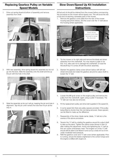
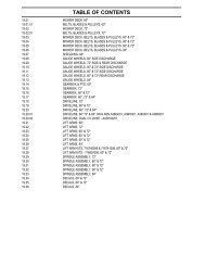
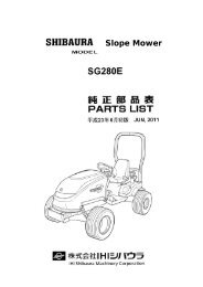
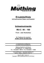
Replacing Gearbox Pulley on VariableSpeed Models1. Drive out spring dowel at bottom of assembly and removeassembly from shaftSlow Down/Speed Up Kit InstallationInstructionsAll fuel and oil should be drained from the mower before commencingthis procedure as the mower will be tipped over. This will avoid the riskof fuel and oil reaching vulnerable parts of the mower.1. Remove the gearbox cover plate from the rear of the mowerhousing (see photo below), and the cover over the ‘V’ belt abovethe housing (where applicable).Photo showsgearbox cover plateremoved to revealthe drive belt.2. Tip the mower on its right side and remove the blade and driverassembly from the crankshaft. You may require a puller to dothis. If so, take care not to damage the crankshaft. Or lose theWoodruff key if it comes off with the driver assembly.2. With new assembly, drive spring dowel into assembly but do notgo into the bore. Slide the assembly onto the shaft and line upthe pin with the hole in the shaft.3. Slacken the gearbox clamp screw (shown below with left rearwheel removed) and rotate the gearbox around its output shaft toloosen the ‘V’ belt.4. Loosen the M8 grub screw on the engine pulley and remove thepulley from the crankshaft, again using a puller if necessary. The‘V’ belt can now also be removed.3. Slide the assembly as far as it will go, keeping the pin and hole inalignment. Tap the pin until it enters the hole then hit pin all theway in.5. Fit the replacement pulley and drive belt supplied in the speed kit.6. In some speed kits there are pulley spacers provided. If the pulleybeing fitted is shorter than the one being removed, these spacerscan be fitted to make up the difference.7. Reassembly of the driver, blade carrier, blade, ‘V’ belt etc is thereverse of the above procedure.8. Tension the ‘V’ belt by rotating the gearbox around its output shaftto take up the slack. Tighten the clamp screw (shown in item 2)after making this adjustment. Avoid over-tightening the ‘V’ belt asthis can cause unnecessary wear. The longest run of the ‘V’ beltshould still be able to be flexed in and out by a total of 6 to 8 mmunder moderate hand pressure.9. Refit the gearbox cover and ‘V’ belt cover (where applicable). Priorto running, ensure the blade is tightened to the correct torque andthe engine is refilled with engine oil.12
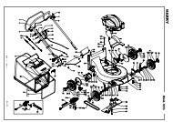
Rear Axle Unit - Rear Wheel DriveModelsDESCRIPTIONAll rear wheel drive mower models have a similar construction,although there are some variations in the components. The outputshaft of the gearbox has a slot at each end to accept sliding pawlswhose ends engage with the three-lobed ramps inside the piniongears. The sliding pawls oscillate back and forth inside the pinions sothe pinion can rotate freely on the shaft in one direction. But rotationin the opposite direction is prevented by the pawls engaging on thesquare faces of the pinion ramps. This engagement transmits the driveto the wheel gears. The action of ‘free-wheeling’ in one direction allowsthe mower to be pushed forward, and to be steered around corners.When the gearbox clutch is engaged, the output shaft rotates thepinions to drive the mower forward. Note that the pinion gears musthave interior ramps of opposite hand, one for each side of the mower.The gears carry the mark ‘RH’ or ‘LH’ inside, adjacent to the ramp,to show whether they are for the Right Hand or Left Hand side of themower. Remember, right and left are as seen by the operator whenstanding at the handle.While the same pawl can be used on either side of the mower, it MUSTbe installed in the slot so that the rounded corners will run smoothly upthe ramps and the square corners will give positive engagement withthe square faces of the pinion ramps.The pinion gear engages with a larger wheel gear, so the wheel axleis parallel to the gearbox output shaft but some distance from it. Thuswhen the rear axle assembly is rotated about the axis of the gearboxoutput shaft, the wheel axle will travel in a circle some distance awayfrom it. This movement of the wheel axle is used to raise and lower theback of the lawnmower. A connecting rod to the front of the mowermoves a similarly offset wheel axle assembly about its rotation point,raising and lowering the front wheels also.MODIFIED PINIONS AND GEARSA manufacturing improvement was made in May 2010. This was achange to a larger tooth profile on the pinions and gears. The originalpinions had 16 teeth and the matching gears had 60 teeth. Now thepinions have 12 teeth and the gears have 45 teeth. Old style pinionsand gears cannot be mixed with the new ones. See the illustrationabove.As the gear ratio is unchanged, and the shaft centre distance is alsounchanged, it would be possible to use an old set on one side ofa mower and a new set on the other, but we recommend fitting acomplete set if any of the old pinions or gears need replacing. Thepawls are unchanged. If you are replacing an old gear with a spacingshoulder behind it, fit spacer No 569479 behind the new gear to bringthe teeth into correct alignment with the pinion.CORRECT PAWL, PINION AND CAP POSITIONSA spring-loaded height adjusting lever mounted on the rear axleassembly permits the mower height to be raised and lowered, andthe lever drops into a notch in the quadrant to hold the mower atthe desired cutting height. A counterbalance spring attached to theconnecting rod takes some of the mower weight to facilitate raisingand lowering the mower.The rear axle assembly has a plate at each end carrying a wheel stubaxle on the outside, and a bearing sleeve on the inside. The inside ofthe bearing sleeve provides a housing for the sealed ballrace of thegearbox output shaft, while the outside of the sleeve carries the plasticpivot bushes on which the axle assembly rotates as the cutting heightis altered.There are two different methods for mounting the rear axle assemblyto the mower housing. In most aluminium housings there is a partcylindrical seat provided for the plastic pivot bushes, and they areheld in place by saddles screwed edgewise into the wall of thehousing. Steel housings, on the other hand, use flanged steel retainercups which fit over the pivot bushes and fit against the outer faces ofthe housing. The cups have threaded inserts for set screws passingthrough the housing wall to clamp the cups in place. Somealuminium housings use the flanged steel cups instead of saddles.(See Step 7 of REMOVING THE REAR AXLE UNIT FROM REARWHEEL DRIVE MOWERS).REMOVING REAR AXLE UNITS FROM REAR WHEEL DRIVEMOWERSPreparation (All models)We strongly advise that all fuel and oil be drained from the mowerbefore commencing this procedure as the mower will be tipped over.This will avoid the risk of fuel and oil reaching vulnerable parts ofthe mower. In any case, this could be a sensible time to make an oilchange.SEE THE NOTE ON ‘POSITIONAL DESCRIPTIONS’ ON PAGE 2.1. Disconnect the counterbalance spring fitted between theconnecting rod and the housing. Take care, as this spring is verystrong. To minimize the spring tension, set the cutting height to itshighest position. Unhook the spring from the housing by passinga strong wire loop around the front hook of the spring, just abovethe housing. With the wire formed into a closed loop, a suitablehandle through the loop will allow the front hook of the spring tobe pulled forward and out of the hole in the housing. Once clearof the housing, the tension on the spring can be slowly releaseduntil it is safe to remove the wire loop.13