
You also want an ePaper? Increase the reach of your titles
YUMPU automatically turns print PDFs into web optimized ePapers that Google loves.
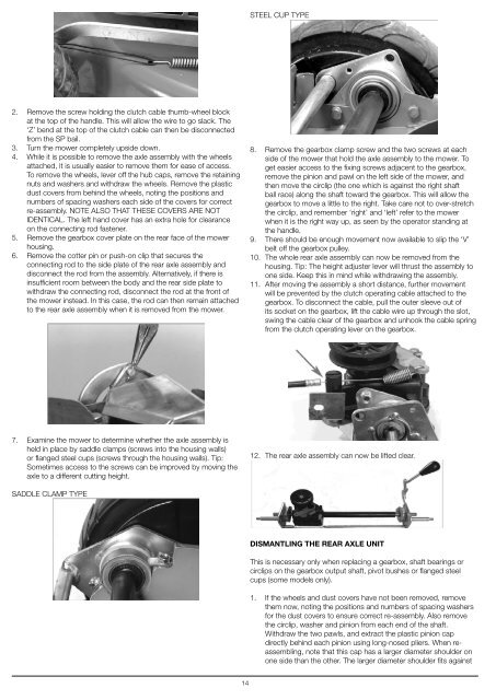
STEEL CUP TYPE2. Remove the screw holding the clutch cable thumb-wheel blockat the top of the handle. This will allow the wire to go slack. The‘Z’ bend at the top of the clutch cable can then be disconnectedfrom the SP bail.3. Turn the mower completely upside down.4. While it is possible to remove the axle assembly with the wheelsattached, it is usually easier to remove them for ease of access.To remove the wheels, lever off the hub caps, remove the retainingnuts and washers and withdraw the wheels. Remove the plasticdust covers from behind the wheels, noting the positions andnumbers of spacing washers each side of the covers for correctre-assembly. NOTE ALSO THAT THESE COVERS ARE NOTIDENTICAL. The left hand cover has an extra hole for clearanceon the connecting rod fastener.5. Remove the gearbox cover plate on the rear face of the mowerhousing.6. Remove the cotter pin or push-on clip that secures theconnecting rod to the side plate of the rear axle assembly anddisconnect the rod from the assembly. Alternatively, if there isinsufficient room between the body and the rear side plate towithdraw the connecting rod, disconnect the rod at the front ofthe mower instead. In this case, the rod can then remain attachedto the rear axle assembly when it is removed from the mower.8. Remove the gearbox clamp screw and the two screws at eachside of the mower that hold the axle assembly to the mower. Toget easier access to the fixing screws adjacent to the gearbox,remove the pinion and pawl on the left side of the mower, andthen move the circlip (the one which is against the right shaftball race) along the shaft toward the gearbox. This will allow thegearbox to move a little to the right. Take care not to over-stretchthe circlip, and remember ‘right’ and ‘left’ refer to the mowerwhen it is the right way up, as seen by the operator standing atthe handle.9. There should be enough movement now available to slip the ‘V’belt off the gearbox pulley.10. The whole rear axle assembly can now be removed from thehousing. Tip: The height adjuster lever will thrust the assembly toone side. Keep this in mind while withdrawing the assembly.11. After moving the assembly a short distance, further movementwill be prevented by the clutch operating cable attached to thegearbox. To disconnect the cable, pull the outer sleeve out ofits socket on the gearbox, lift the cable wire up through the slot,swing the cable clear of the gearbox and unhook the cable springfrom the clutch operating lever on the gearbox.7. Examine the mower to determine whether the axle assembly isheld in place by saddle clamps (screws into the housing walls)or flanged steel cups (screws through the housing walls). Tip:Sometimes access to the screws can be improved by moving theaxle to a different cutting height.12. The rear axle assembly can now be lifted clear.SADDLE CLAMP TYPEDISMANTLING THE REAR AXLE UNITThis is necessary only when replacing a gearbox, shaft bearings orcirclips on the gearbox output shaft, pivot bushes or flanged steelcups (some models only).1. If the wheels and dust covers have not been removed, removethem now, noting the positions and numbers of spacing washersfor the dust covers to ensure correct re-assembly. Also removethe circlip, washer and pinion from each end of the shaft.Withdraw the two pawls, and extract the plastic pinion capdirectly behind each pinion using long-nosed pliers. When reassembling,note that this cap has a larger diameter shoulder onone side than the other. The larger diameter shoulder fits against14