

installation instructions 2-panel vinyl sliding doors - Superior Windows
installation instructions 2-panel vinyl sliding doors - Superior Windows
installation instructions 2-panel vinyl sliding doors - Superior Windows

Create successful ePaper yourself
Turn your PDF publications into a flip-book with our unique Google optimized e-Paper software.
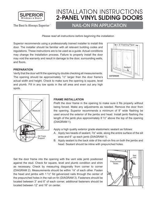
INSTALLATION INSTRUCTIONS2-PANEL VINYL SLIDING DOORSNAIL-ON FIN APPLICATIONPlease read all <strong>instructions</strong> before beginning the <strong>installation</strong>.<strong>Superior</strong> recommends using a professionally trained installer to install thisdoor. The installer should be familiar with all relevant building codes andregulations. These <strong>instructions</strong> are to be used as a guide. Actual conditionsmay change the <strong>installation</strong> process. Failure to properly install the doormay void the warranty and result in damage to the door, surrounding walls,and floors.9” Flashing PaperPREPARATIONVerify that the door will fit the opening by double checking all measurements.The opening should be approximately 1/2” larger than the door frame’sactual width and height. Check to make sure the opening is square, leveland plumb. Fill in any low spots in the sill area and even out any highspots.EXTERIORSealant1MeasureFRAME INSTALLATIONPrefit the door frame in the opening to make sure it fits properly withoutbeing forced. Make any adjustments as needed. Remove the door fromthe opening. <strong>Superior</strong> recommends a minimum of 9” wide flashing beused around the exterior of the jambs and head. Install jamb flashing thelength of the jamb plus approximately 8 1/2” above the top of the opening(DIAGRAM 1).2Sill TrackSupportApply a high quality exterior grade elastomeric sealant as follows:A. Apply two beads of sealant, 3/8” wide, along the entire surface of the sillarea and 6” up each jamb (DIAGRAM 1).B. Apply sealant to the back side of the nail-on fins on both the jambs andhead. Sealant should be inline with prepunched holes.Set the door frame into the opening with the vent side jamb positionedagainst the stud. Check for square, level and plumb condition and shimas necessary. Check by measuring diagonally from corner to corner(DIAGRAM 2). Measurements should be within 1/8” of each other. Fastenthe head and jambs with 1 1/2” 6d galvanized nails through the center ofthe prepunched holes in the nail-on fin (DIAGRAM 3). Fasteners should belocated between 3” and 6” of each corner, additional fasteners should belocated between 12” and 16” on center.PrepunchedHolesNailInto3
EXTERIOR9” Flashing Paper OverNail-on Fin and SealantFRAME INSTALLATION CON’TDo not use an automatic nailer. Caution should be made to avoid bowingframe. Apply an additional bead of sealant to the exterior face of the nailonfin at the door’s head. Bead should be inline with prepunched holesand over the top of all fasteners. Apply 9” wide flashing above the openingbeing sure to imbed the flashing in the sealant. Flashing should extendpast the door by 10” (DIAGRAM 4). Check the sill under the screen track.If it does not make contact or sags, a full length support may be needed(DIAGRAM 2).45 6FIXED PANEL INSTALLATIONLocate the sill riser bar and insert it into the center track of the sill makingsure it butts up against the fixed jamb. Gently tap it down into the sill toensure proper <strong>installation</strong>. Standing on the exterior, lift the fixed <strong>panel</strong> (the<strong>panel</strong> that has not been punched for the handle) and place the <strong>panel</strong> intothe center channel of the head (DIAGRAM 5) and lower it on to the sill riser.NOTE: The glazing bead should face the exterior. Slide <strong>panel</strong> sidewaysinto the jamb as far as it will go (DIAGRAM 6). Install the head cap into thecenter track by gently tapping it into the open space between the vent jamband the fixed <strong>panel</strong>. Repeat his process with the sill cap. Caps are precutto fit. If it appears too long, make sure the fixed <strong>panel</strong> is pushed all the wayinto the jamb. From the interior, secure the fixed <strong>panel</strong> into the jamb with 2- #8 x 1” screws through the wall of the jamb and into the stile of the fixed<strong>panel</strong> (DIAGRAM 7). Locate one screw approximately 2” from the top of the<strong>panel</strong> and the second at the center point.INTERIOR7
FIXED PANEL INTERLOCK INSTALLATION – SERIES 9800 / 9900From the interior, position the interlock clip next to the fixed <strong>panel</strong> with thebottom of the clip resting in sill (DIAGRAM 8). Starting at the bottom andworking up, tap the interlock clip into the groove on the fixed <strong>panel</strong>.Interlock ClipGently TapInsertSeries 9800 / 99008FIXED PANEL INTERLOCK INSTALLATION – SERIES 9100 / 9901From the interior, position the interlock clip next to the fixed <strong>panel</strong> with thebottom of the clip resting on the sill (DIAGRAM 9). Starting at the bottomand working up, tap the interlock clip into the groove on the fixed <strong>panel</strong>.Interlock ClipGently TapInsertSeries 9100 / 99019VENT PANEL INSTALLATIONCheck and remove any debris that could interfere with the <strong>doors</strong> operation.Standing on the interior, lift the vent <strong>panel</strong> into the first channel of the headand lower it onto the track (DIAGRAM 10).10HARDWARE INSTALLATION – SERIES 9800The mortise lock is already installed in the door. Install the handle byproceeding as follows. Insert the thumb actuator into the slot on the mortiselock. Slide the anti-punchout spacer into the hollow of the exterior handle.Position the interior and exterior handles onto the door. Using 2 - #8 x 2”machine screws secure the handles to the door. Screws are installed fromthe interior side. Install the keeper on to the jamb with 2 - #8 x 2 1/2” woodscrews into the elongated holes. Do not tighten. Check operation of thelock once the door locks properly. Install the two remaining screws andtighten all screws (DIAGRAM 11).Series 9800 Keeper11
HARDWARE INSTALLATIONThe mortise lock is already installed in the door. Proceed as follows to installthe handle. Insert the thumb actuator into the slot on the mortise lock. Slidethe anti-punchout spacer into the hollow of the exterior handle. Position theinterior and exterior handles on to the door. Secure the handles to the doorusing 2 - #8 x 2” machine screws. Screws are installed from the interiorside. Install the keeper on to the jamb with 2 - #8 x 2 1/2” wood screws intothe elongated holes which located at the top and bottom of the keeper.Do not tighten. Check operation of the lock once the door locks properly.Install the two remaining screws and tighten all screws (DIAGRAM 12). Ifthe locking hooks are not the right length, they can be adjusted by turningthe slotted screws. One is located directly above the top hook and anotherdirectly below the lower hook.12KeeperFINAL ADJUSTMENTAdjust all door rollers. The adjustment is located at the bottom of theinterlock and lead stiles (DIAGRAM 13). There are two screws at this point.The lower screw is the adjustment screw. It may help to lift up on the <strong>panel</strong>when adjusting. The active <strong>panel</strong> should be parallel to the fixed <strong>panel</strong> andframe when properly adjusted. Open the <strong>panel</strong> so that there is a 1/2” gapvertically between the <strong>panel</strong> and frame. The gap should be the same topto bottom. Readjust the rollers as needed to properly align. Check the lockto make sure it operates properly. It may be necessary to readjust at thistime. Install the rubber bumper into the header channel of the active <strong>panel</strong>where it meets the fixed side jamb. This will act as a stop when the dooris in the full open position. Apply a continuous bead of sealant aroundthe entire perimeter of the door making sure it makes contact with thesubstrate. Do not block weep holes when applying sealant to the sill.13SCREEN INSTALLATIONFrom the exterior, lift the screen into the outside channel of the head andlower onto the sill track. Using a flat screwdriver or putty knife, lift the screen’sspring loaded wheels up and onto the screen track (DIAGRAM 14). Openthe screen so that there is a 1/2” gap vertically between the screen and thedoor frame, (DIAGRAM 15). The space should be the same top to bottom.Adjust the screen rollers as needed to properly align.1 /2”1 /2”Screen Door14INST9900N-0908 ©2010 <strong>Superior</strong> <strong>Windows</strong> & Doors superior-windows.com15
INSTALLATION INSTRUCTIONS3-PANEL VINYL SLIDING DOORSOXO • XOO • OOXOXO DOORSDetermine which fixed <strong>panel</strong> will interlock onto the vent <strong>panel</strong> and which one will have the vent <strong>panel</strong> lockagainst it. For the <strong>panel</strong> that will interlock, follow the standard 2-<strong>panel</strong> <strong>instructions</strong> through FIXED PANELINSTALLATION then proceed as follows.Install the second fixed <strong>panel</strong> into the inside track. Place the OXO adapter next to this <strong>panel</strong> with the screenclip facing the exterior. Beginning at the bottom, gently tap the adapter onto the fixed <strong>panel</strong>. Secure theadapter to the fixed <strong>panel</strong> by drilling 6 - 1/8” pilot holes through the adapter and into the <strong>panel</strong> – two each atthe top, bottom, and center. Secure with the #8 x 1” pan head screws. Place the screen clip next to the frame,beginning at the bottom, gently tap into place (DIAGRAM 1). Return to the standard <strong>installation</strong> <strong>instructions</strong>.XOO / OOX DOORSFollow the standard 2-<strong>panel</strong> <strong>instructions</strong> through FIXED PANEL INSTALLATION, however do not attach aninterlock clip to the first <strong>panel</strong>. Install the second sill riser making sure it fits tightly against the first riser.Place the O/O adapter next to the installed fixed <strong>panel</strong> (DIAGRAM 2). Starting at the bottom and working up,gently tap the adapter onto the <strong>panel</strong>. Secure the adapter to the <strong>panel</strong> by drilling 6 - 1/8” pilot holes throughthe adapter and into the <strong>panel</strong> – two each at the top, middle, and bottom. Secure with #8 x 1” pan headscrews. Install the second fixed <strong>panel</strong> and continue with the standard <strong>installation</strong> <strong>instructions</strong>.DIAGRAM 1INSIDEOXO DOORROLLING PANELOXOAdapter#8x1” Sheet Metal ScrewsJambFIXED PANELw/ groove for Interlock ClipInterlock ClipScreen ClipFIXED PANELw/ like vertical stilesJambXOO / OOX DOOR DIAGRAM 2ROLLING PANELINSIDE#8x1” Sheet Metal ScrewsInterlock ClipJambFIXED PANELw/ groove for Interlock ClipO/OAdapter/Screen StopFIXED PANELw/ like vertical stilesJamb
INSTALLATION INSTRUCTIONS4-PANEL VINYL SLIDING DOORSOXXOFollow the standard 2-<strong>panel</strong> <strong>instructions</strong> throughFIXED PANEL INSTALLATION and continue with the following stepsOXXO ADDITIONAL INSTALLATION STEPSBefore installing the vent <strong>panel</strong>s, place the OXXO adapter onto one vent <strong>panel</strong>. Starting at the bottom andworking up gently, tap the OXXO adapter onto one of the vent <strong>panel</strong>s. (NOTE: Allow 1/4” clearance from thesill so the adapter can move with the vent <strong>panel</strong>.) Secure the adapter to the vent <strong>panel</strong> by drilling 6 - 1/8” holesthrough the adapter and into the vent <strong>panel</strong> – two each at the top, bottom, and center. Secure with #8 x 1”supplied screws (DIAGRAM 1). Return to the standard <strong>installation</strong> <strong>instructions</strong>.OXXO ADDITIONAL SCREEN INSTALLATION STEPSInstall both screens and adjust. Close both screens making sure they meet at the center. Open one screenand place the “L” bracket in the head track with one side against the screen. Secure “L” bracket and closeboth screens (DIAGRAM 2).DIAGRAM 1INSIDEFIXED PANELOXXO DOORROLLING PANELSOXXOAdapter#8x1” Sheet Metal ScrewsInterlockClipInterlockClipFIXED PANELJambJambDIAGRAM 2“L” BracketINSTOXO-1107 ©2010 <strong>Superior</strong> <strong>Windows</strong> & Doors superior-windows.com
INSTALLATION INSTRUCTIONSREVERSING PANEL DIRECTIONXO & OX VINYL SLIDING DOORSPlease read all <strong>instructions</strong> before beginning the <strong>installation</strong>.These <strong>instructions</strong> are an addendum to <strong>Superior</strong>’s standard <strong>vinyl</strong> <strong>sliding</strong> door <strong>installation</strong> <strong>instructions</strong> to assistthe installer when it becomes necessary to switch the direction of the <strong>panel</strong>s (68 high only) during or after<strong>installation</strong>. Please refer to our 2-<strong>panel</strong> <strong>vinyl</strong> <strong>sliding</strong> <strong>doors</strong> <strong>installation</strong> <strong>instructions</strong> to complete all <strong>installation</strong>s.(Instructions are for Series 9800, 9100, 9900 and 9901.)1WheelAssemblyAttachmentScrewAccess Hole ForRoller AdjustmentsVENT PANEL REMOVALBegin by removing the two screws that hold the handles in place. Carefullyset the handles aside, so they are not damaged. Open the <strong>sliding</strong> <strong>panel</strong>at least halfway, the <strong>panel</strong> must be moved far enough to the center toclear the anti-lift clip located in the head. Lift the <strong>panel</strong> up into the headuntil the rollers clear the bottom track and remove to the inside. Set the<strong>panel</strong> firmly on a pair of saw horses or a table with the interior facing upbeing careful not to scratch or damage the <strong>panel</strong>.NOTE: It may be necessary to retract the rollers before removing the<strong>panel</strong>. The roller adjustment screw can be found on the bottom of the<strong>panel</strong> (DIAGRAM 1).HARDWARE REVERSALThe lock assembly on the Series 9800 is held in place by two screws located on the <strong>panel</strong>’s edge. (CAUTION:When these screws are removed the lock assembly must be held in place by hand.) Slide the lock assemblyout and reverse its direction by flipping it end to end. Reinstall the fasteners. Install the handles making sureyou reverse their original direction (thumb turn should be below the handle and screw heads are on theinterior). Remove the keeper from the jamb and reinstall it on the opposite jamb.NOTE: If the <strong>sliding</strong> door utilizes a dual-point lock, you only need to remove and reverse the direction of thehandles. A dual-point lock does not need to be reversed.ROLLER ASSEMBLY REVERSALThere are two screws on the bottom edge of the door (DIAGRAM 1). Remove the wheel assembly attachmentscrew (top screw) and slide the wheel assembly out from the bottom rail. Place the assembly in the rail atthe opposite end of the door (this will become the bottom rail). Secure by replacing the wheel assemblyattachment screw. Repeat this process on the other roller assembly.
FIXED PANEL REMOVALRemove the head and sill cap from the center track. These areused to block the fixed <strong>panel</strong> in position and can be removed bycarefully prying up and out (DIAGRAM 2). Beginning at the top ofthe fixed <strong>panel</strong> and working down, pry the interlock clip off of the<strong>panel</strong> (DIAGRAM 3). Care must be taken to avoid scratching orgouging the <strong>vinyl</strong>. Remove the fixed <strong>panel</strong>. Snap out the sill riserthat is located below the fixed <strong>panel</strong> (DIAGRAM 4).Pry upsill cap.2REINSTALLATION OF DOOR PANELSReturn to <strong>Superior</strong>’s <strong>installation</strong> <strong>instructions</strong> at the fixed <strong>panel</strong> <strong>installation</strong> step.PryInterlock ClipSeries 9800 / 9900Interlock ClipRiserSeries 9100 / 9901Pry34INSTRP-1107 ©2010 <strong>Superior</strong> <strong>Windows</strong> & Doors superior-windows.com