Investigation into a new hybrid forming process: Incremental sheet ...
Investigation into a new hybrid forming process: Incremental sheet ...
Investigation into a new hybrid forming process: Incremental sheet ...

Create successful ePaper yourself
Turn your PDF publications into a flip-book with our unique Google optimized e-Paper software.
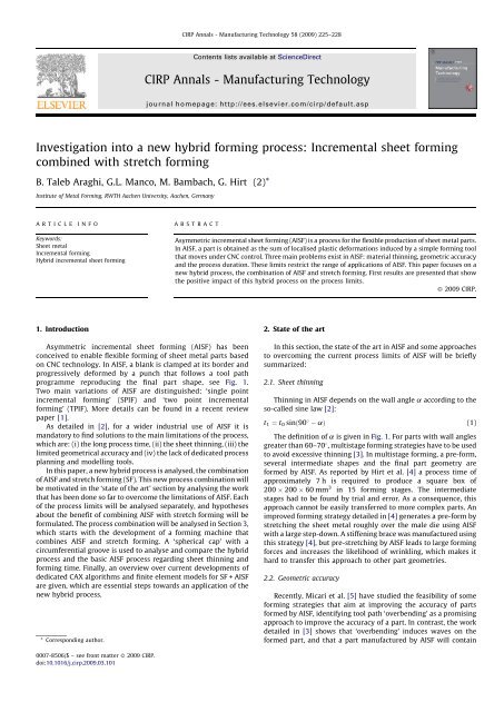
CIRP Annals - Manufacturing Technology 58 (2009) 225–228Contents lists available at ScienceDirectCIRP Annals - Manufacturing Technologyjournal homepage: http://ees.elsevier.com/cirp/default.asp<strong>Investigation</strong> <strong>into</strong> a <strong>new</strong> <strong>hybrid</strong> <strong>forming</strong> <strong>process</strong>: <strong>Incremental</strong> <strong>sheet</strong> <strong>forming</strong>combined with stretch <strong>forming</strong>B. Taleb Araghi, G.L. Manco, M. Bambach, G. Hirt (2)*Institute of Metal Forming, RWTH Aachen University, Aachen, GermanyARTICLEINFOABSTRACTKeywords:Sheet metal<strong>Incremental</strong> <strong>forming</strong>Hybrid incremental <strong>sheet</strong> <strong>forming</strong>Asymmetric incremental <strong>sheet</strong> <strong>forming</strong> (AISF) is a <strong>process</strong> for the flexible production of <strong>sheet</strong> metal parts.In AISF, a part is obtained as the sum of localised plastic deformations induced by a simple <strong>forming</strong> toolthat moves under CNC control. Three main problems exist in AISF: material thinning, geometric accuracyand the <strong>process</strong> duration. These limits restrict the range of applications of AISF. This paper focuses on a<strong>new</strong> <strong>hybrid</strong> <strong>process</strong>, the combination of AISF and stretch <strong>forming</strong>. First results are presented that showthe positive impact of this <strong>hybrid</strong> <strong>process</strong> on the <strong>process</strong> limits.ß 2009 CIRP.1. Introduction2. State of the artAsymmetric incremental <strong>sheet</strong> <strong>forming</strong> (AISF) has beenconceived to enable flexible <strong>forming</strong> of <strong>sheet</strong> metal parts basedon CNC technology. In AISF, a blank is clamped at its border andprogressively deformed by a punch that follows a tool pathprogramme reproducing the final part shape, see Fig. 1.Two main variations of AISF are distinguished: ‘single pointincremental <strong>forming</strong>’ (SPIF) and ‘two point incremental<strong>forming</strong>’ (TPIF). More details can be found in a recent reviewpaper [1].As detailed in [2], for a wider industrial use of AISF it ismandatory to find solutions to the main limitations of the <strong>process</strong>,which are: (i) the long <strong>process</strong> time, (ii) the <strong>sheet</strong> thinning, (iii) thelimited geometrical accuracy and (iv) the lack of dedicated <strong>process</strong>planning and modelling tools.In this paper, a <strong>new</strong> <strong>hybrid</strong> <strong>process</strong> is analysed, the combinationof AISF and stretch <strong>forming</strong> (SF). This <strong>new</strong> <strong>process</strong> combination willbe motivated in the ‘state of the art’ section by analysing the workthat has been done so far to overcome the limitations of AISF. Eachof the <strong>process</strong> limits will be analysed separately, and hypothesesabout the benefit of combining AISF with stretch <strong>forming</strong> will beformulated. The <strong>process</strong> combination will be analysed in Section 3,which starts with the development of a <strong>forming</strong> machine thatcombines AISF and stretch <strong>forming</strong>. A ‘spherical cap’ with acircumferential groove is used to analyse and compare the <strong>hybrid</strong><strong>process</strong> and the basic AISF <strong>process</strong> regarding <strong>sheet</strong> thinning and<strong>forming</strong> time. Finally, an overview over current developments ofdedicated CAX algorithms and finite element models for SF + AISFare given, which are essential steps towards an application of the<strong>new</strong> <strong>hybrid</strong> <strong>process</strong>.* Corresponding author.In this section, the state of the art in AISF and some approachesto overcoming the current <strong>process</strong> limits of AISF will be brieflysummarized:2.1. Sheet thinningThinning in AISF depends on the wall angle a according to theso-called sine law [2]:t 1 ¼ t 0 sinð90 aÞ (1)The definition of a is given in Fig. 1. For parts with wall anglesgreater than 60–708, multistage <strong>forming</strong> strategies have to be usedto avoid excessive thinning [3]. In multistage <strong>forming</strong>, a pre-form,several intermediate shapes and the final part geometry areformed by AISF. As reported by Hirt et al. [4] a <strong>process</strong> time ofapproximately 7 h is required to produce a square box of200 200 60 mm 3 in 15 <strong>forming</strong> stages. The intermediatestages had to be found by trial and error. As a consequence, thisapproach cannot be easily transferred to more complex parts. Animproved <strong>forming</strong> strategy detailed in [4] generates a pre-form bystretching the <strong>sheet</strong> metal roughly over the male die using AISFwith a large step-down. A stiffening brace was manufactured usingthis strategy [4], but pre-stretching by AISF leads to large <strong>forming</strong>forces and increases the likelihood of wrinkling, which makes ithard to transfer this approach to other part geometries.2.2. Geometric accuracyRecently, Micari et al. [5] have studied the feasibility of some<strong>forming</strong> strategies that aim at improving the accuracy of partsformed by AISF, identifying tool path ‘overbending’ as a promisingapproach to improve the accuracy of a part. In contrast, the workdetailed in [3] shows that ‘overbending’ induces waves on theformed part, and that a part manufactured by AISF will contain0007-8506/$ – see front matter ß 2009 CIRP.doi:10.1016/j.cirp.2009.03.101
226B.T. Araghi et al. / CIRP Annals - Manufacturing Technology 58 (2009) 225–228Fig. 1. Process principle and variations.considerable residual stresses as a consequence of the cyclicloading and unloading during <strong>forming</strong>.2.3. Forming timeAISF is an incremental <strong>forming</strong> <strong>process</strong>. The time to manufacturea part is determined by the length of the tool path and theaverage travelling speed of the <strong>forming</strong> tool. Bambach [2] showsthat the <strong>process</strong> time required to manufacture a conical frustum ofheight h, bottom radius r=hand top radius 2r scales quadraticallywith h: assuming an average speed of 500 mm/s and a step-downof 0.2 mm for the tool path (cf. [2]), the <strong>forming</strong> time is alreadygreater than 1 day for a conical frustum of 1 m height.2.4. Finite element modellingAn overview of <strong>process</strong> models for AISF is given in [1,3]. Inparticular [3], analyses the CPU time required to simulate the<strong>forming</strong> of the conical frustum mentioned in the precedingparagraph on a single <strong>process</strong>or machine using a dynamic explicitcode. The FEA takes almost 10 days using tool path with a stepdownof 0.5 mm, and more than 20 days with a step-down of0.2 mm. This makes FEA prohibitive for larger parts.3. Hybrid AISF: stretch <strong>forming</strong> + AISFAlthough it is not inconceivable that ways will be found in thefuture to overcome the <strong>process</strong> limits of AISF and to enable modelbased<strong>process</strong> planning, an alternative <strong>process</strong> will be analysed inthis paper: the combination of AISF and stretch <strong>forming</strong>. Theconcept of the <strong>new</strong> <strong>hybrid</strong> <strong>process</strong> is illustrated in Fig. 2, whichindicates that stretch <strong>forming</strong> is used to create a pre-form in a first<strong>forming</strong> step. Stretch <strong>forming</strong> will not yield the final part geometry(otherwise the <strong>process</strong> combination would not be necessary).Hence, features such as pockets, corrugations or grooves that arenot formed during SF are formed using AISF.For the discussion to follow, it is useful to introducedesignations for the surface area of the <strong>sheet</strong> in contact withthe die after stretch <strong>forming</strong>, G SF , and its compliment, the surfacearea of the <strong>sheet</strong> that is not in contact with the die after stretch<strong>forming</strong>, denoted by G P0 . G P0 is available to form those partfeatures by AISF that cannot be formed by stretch <strong>forming</strong>. Thesefeatures cover a surface area G P , which is the area of the die that isnot in contact with the <strong>sheet</strong> metal after stretch <strong>forming</strong>. Thefollowing advantages are expected from the combination of AISFand SF:1. The <strong>process</strong> time of AISF increases with the surface area coveredby the tool path. The <strong>process</strong> time for stretch <strong>forming</strong> scales withthe total height of the part. Hence, the combination of AISF andSF is expected to have a shorter <strong>process</strong> time for shallow partswith a large surface area.2. For a given part, AISF and SF yield a different distribution of<strong>sheet</strong> thinning. If a pre-form can be produced by SF that leavesmore <strong>sheet</strong> thickness for part features such as pockets (G P0 ) thanwould be available if the same pre-form is produced by AISF, the<strong>process</strong> combination should yield less thinning in the pocketareas compared to AISF. Thus, the <strong>process</strong> combination shouldoffer <strong>new</strong> possibilities to overcome the thinning limits of AISF.3. Stretch <strong>forming</strong> is known to yield parts with a good accuracy dueto the tensile state of stress [6]. AISF could benefit from stretch<strong>forming</strong> in two ways: (i) by creating a pre-form using SF thatwould be more accurate than a pre-form manufactured by AISF.(ii) By superimposing tensile stresses during AISF, i.e. byapplying stretch <strong>forming</strong> simultaneously to AISF in order toreduce the residual stresses induced by the cyclic bending andunbending.4. In the same way as the <strong>forming</strong> time is reduced, the time neededfor the simulation of the <strong>process</strong> should be smaller for SF + AISFcompared to AISF. Hence, <strong>process</strong> planning and optimisationwould become more viable for the <strong>process</strong> combination than forAISF.The statements 1–4 do not hold for arbitrary parts. It will benecessary to identify part geometries for which the <strong>process</strong> doesoffer these advantages. Due to the restricted space, only thehypotheses 1, 2 and 4 are tested in this paper. A hemispherical basegeometry with circumferential groove is used to analyse thepossible benefits of the <strong>process</strong> combination compared to pureAISF. As detailed above, the machine set-up will be discussed firstbefore the experimental tests are given.4. Process investigation4.1. Experimental set-upFig. 3 shows an AMINO DNLC-RB <strong>forming</strong> machine in which theoriginal hydraulic control system of the frame was replaced by fourscrews jacks driven by a servo motor. The screw movements arecontrolled by a closed-loop control system. With this set-up, adownward force of 50 kN can be exerted in order to performstretch <strong>forming</strong> experiments on soft materials, e.g. aluminiumalloys.4.2. Experimental testsFig. 2. Principle of the <strong>process</strong> combination.As mentioned above, a hemispherical part with circumferentialgrooves serves as benchmark part for the analysis of the <strong>sheet</strong>
B.T. Araghi et al. / CIRP Annals - Manufacturing Technology 58 (2009) 225–228 227Fig. 3. The experimental set-up.thinning induced by the combined <strong>process</strong>. Two experiments willbe presented:1. The <strong>forming</strong> of a section of a hemisphere without pockets wasconsidered in order to analyse the differences in material flowinduced by AISF and SF. The aim was to analyse <strong>sheet</strong> thinningusing a simple part for which both AISF and stretch <strong>forming</strong> canbe treated analytically.2. The <strong>forming</strong> of a section of a hemisphere with a groove aroundthe circumference is analysed to show the benefit of the <strong>process</strong>combination of AISF and SF compared to pure AISF both in termsof <strong>sheet</strong> thinning and <strong>forming</strong> time.A cap of a hemisphere was formed by AISF and by stretch<strong>forming</strong> using a die of 240 mm radius and 1 mm AA1050-O <strong>sheet</strong>s.The <strong>forming</strong> depth was 25 mm, which was sufficient to show thedifferent thinning behaviour of AISF and SF. The measuredthickness distributions are given in Fig. 4. The <strong>sheet</strong> thickness inAISF decreases in radial direction with increasing wall angle, inaccordance with the sine law, Eq. (1).Sheet thinning in stretch <strong>forming</strong> over a hemispherical punchhas been analysed e.g. in [7]. Under frictionless conditions, themaximum amount of thinning occurs at the pole. With non-zerofriction, the maximum thinning can be found at a certain distancefrom the pole. After the maximum, the <strong>sheet</strong> thinning drops inradial direction, which is in contrast to the course of <strong>sheet</strong> thinningobtained by AISF. Two conclusions can be drawn from this result:1. Stretch <strong>forming</strong> can be used to induce thinning in areas that wouldnot be deformed by AISF, in this case in the pole. Hence, thecombination of AISF and SF offers the possibility to achieve a morehomogeneous thickness distribution compared to either SF or AISF.2. There is a certain point along the radius where AISF and SFinduce the same amount of thinning. Beyond that point, lessthinning is generated by SF than by AISF. If a pocket is lyingbeyond that point, more material would be available to form thepocket when a pre-form made by SF is used.From the theory of stretch <strong>forming</strong> over a hemispherical punchit follows that the position of maximum thinning in SF and theradial thickness distribution changes with the <strong>forming</strong> depth. Thepoint at which AISF and SF yield equal thickness reduction isshifted radially outwards for greater <strong>forming</strong> depths.Fig. 5. Comparison of AISF and SF + AISF for a spherical cap with a groove.In order to verify the second statement, a section of ahemisphere with a circumferential pocket was formed (Fig. 5)using a male aluminium die and DC06 mild steel <strong>sheet</strong>s with a<strong>sheet</strong> thickness of 0.7 mm. In the case of the <strong>hybrid</strong> SF + AISF<strong>process</strong>, a pre-form is created by stretching the <strong>sheet</strong> over the dieto a <strong>forming</strong> depth of 80 mm. After that, the circumferential grooveis formed by AISF. To have comparable conditions to stretch<strong>forming</strong>, the AISF <strong>process</strong> is performed in two stages: first, a preformis created that corresponds to the pre-form created by SF. In asecond <strong>forming</strong> step, the pocket area is created. For the AISFoperations, both in <strong>hybrid</strong> and in pure AISF, a punch diameter of30 mm and a tool step-down of 0.1 mm were used.Fig. 6 shows the comparison of the thickness distributionobtained with the <strong>hybrid</strong> <strong>process</strong> and pure AISF along a radialsection. Both for AISF and SF + AISF, the maximum thicknessreduction was measured in the groove. The maximum measuredthinning is smaller for SF + AISF and the distribution of the thicknessalong the section is more uniform than in the case of pure AISF.It is worth mentioning that the stretch <strong>forming</strong> unit does notoffer enough force to manufacture a complete hemisphere bystretch <strong>forming</strong> of steel <strong>sheet</strong>s. Hence, only a spherical cap wasconsidered, and the groove had to be placed in an area where theadvantage of the <strong>process</strong> combination is not overly pronounced.4.3. Process modellingA finite element model was set-up in LS-DYNA for the <strong>forming</strong> ofthe grooved sphere both for pure AISF and the combined <strong>process</strong>. Inthe FE model for SF + AISF, the <strong>sheet</strong> was meshed with 13,500 shellelements for the first <strong>forming</strong> stage, i.e. the stretch <strong>forming</strong>.Automatic remeshing was applied in the AISF <strong>forming</strong> step whichyielded approximately 30,000 elements at the end of the simulation.The CPU time for the simulation of the stretch <strong>forming</strong> step was 2 h,while the simulation of the <strong>forming</strong> of the groove took approximately6 days on a two <strong>process</strong>or machine. Fig. 7 shows the distribution ofmajor surface strains measured on the formed part using a ‘gomARGUS’ system in comparison with the numerical results.The numerical and experimental results show a similardeformation pattern. The comparison of the results along a radialsection line in Fig. 7 shows that the FEA predicts well the strainsfound in the experiment.In the simulation of pure AISF, a fine mesh with 30,000 elementshas to be used from the beginning. Due to the length of the toolFig. 4. Comparison of thickness reduction induced by AISF and stretch <strong>forming</strong>.Fig. 6. Comparison of thickness for pure AISF and AISF + SF.
228B.T. Araghi et al. / CIRP Annals - Manufacturing Technology 58 (2009) 225–228Fig. 8. Comparison of FEA and experiments for AISF.Fig. 7. Comparison of FEA and experiments for SF + AISF.path, 39 days were needed to simulate the whole AISF <strong>process</strong>.Fig. 8 shows a comparison of measured and simulated majorstrains along a radial section, similar to Fig. 7. Trials showed thatthe simulation cannot be sped up by applying more mass scaling orusing less elements without losing accuracy.The results show that SF + AISF has the advantage that thesimulation of the stretch <strong>forming</strong> can be completed in a relativelyshort time, even for a larger part, which makes it possible tosimulate and optimise at least the first <strong>forming</strong> stage.4.4. CAX developmentIn order to save time through the <strong>process</strong> combination of AISFand SF compared to pure AISF, the time needed for the stretch<strong>forming</strong> and the time needed to form the remaining features usingAISF must be minimised. However, the areas G, G P0 and G P shownin Fig. 2 are not known a priori, but are the result of the stretch<strong>forming</strong> operation and the springback after <strong>forming</strong>. For aminimum <strong>forming</strong> time per part, it is necessary to identify theregions which have to be formed by AISF. Since the prediction ofthe part shape after SF concerning the thickness distribution andgeometry is not possible analytically for complicated shapes, theutilisation of FEA is indispensable.To detect the sections that need AISF <strong>process</strong>ing, the <strong>process</strong>chain depicted in Fig. 9 was developed, which enables to optimisethe <strong>process</strong> time and provides the NC-codes for both SF and AISF.First, the target part is transferred to Unigraphics NX. With NX, theNC-path for SF is generated and transferred to LS-DYNA. The stretch<strong>forming</strong> simulation in LS-DYNA yields the part geometry and <strong>sheet</strong>thickness distribution. This information is transferred back to NX. Analgorithm that detects deviations between the simulated geometryand the target geometry was implemented in UG NX. This algorithmidentifies the areas that need to be deformed by AISF and creates theNC-path programmes for the <strong>forming</strong> of these areas. This approachwas used to optimise the tool paths for the benchmark part. The<strong>forming</strong> time using AISF was 35 min, which could be reduced to20 min in the combined <strong>process</strong>.4.5. Summary and outlookA <strong>new</strong> <strong>hybrid</strong> <strong>process</strong>, the combination of AISF and stretch<strong>forming</strong> was put forward and investigated in this paper. It can beconcluded that with the <strong>process</strong> combination of AISF and SF: A noticeable reduction of production time compared to AISF ispossible, especially when the areas that need to be <strong>process</strong>ed byAISF are identified in advance. In comparison to AISF a more uniform thickness distributionwith a reduced amount of maximum thinning can be achieved. Process planning based on FEA seems to be more viable than forAISF.Future research will focus on the effect of the <strong>process</strong>combination of SF and AISF on the geometrical accuracy and the<strong>forming</strong> limits. The latter is important when part features such aspockets have to be formed from a pre-stretched <strong>sheet</strong>. From anapplication point of view it seems important to consider industrialparts in the future.AcknowledgmentsThe authors would like to thank the German ResearchFoundation (DFG) for the support of the depicted research withinthe Cluster of Excellence ‘‘Integrative Production Technology forHigh Wage Countries’’.Parts of this research and development are funded by theGerman Federal Ministry of Education and Research (BMBF) withinthe Framework Concept ‘‘Research for Tomorrow’s Production’’(fund number: 02PU2104) and managed by the Project ManagementAgency Forschungszentrum Karlsruhe (PTKA), Productionand Manufacturing Technologies Division (PFT).ReferencesFig. 9. CAX <strong>process</strong> chain.[1] Jeswiet J, Micari F, Hirt G, Bramley A, Duflou J, Allwood J (2005) AsymmetricSingle Point <strong>Incremental</strong> Forming of Sheet Metal. Annals of the CIRP 54(2):623–650.[2] Bambach M (2008) Process Strategies and Modelling Approaches for Asymmetric<strong>Incremental</strong> Sheet Forming, Umformtechnische Schriften Band, 139. Shaker Verlag,Aachen.[3] Hirt G, Ames J, Bambach M, Kopp R (2004) Forming Strategies and ProcessModelling for CNC <strong>Incremental</strong> Sheet Forming. Annals of the CIRP 52(1):203–206.[4] Hirt G, Ames J, Bambach M (2005) A New Forming Strategy to Realise PartsDesigned for Deep Drawing by <strong>Incremental</strong> CNC Sheet Forming. Steel Research71(2):160–166.[5] Micari F, Ambrogio G, Filice L (2007) Shape and Dimensional Accuracy in SinglePoint <strong>Incremental</strong> Forming: State of the Art and Future Trends. Journal ofMaterials Processing Technology 191(1–3):390–395.[6] Lange K (1990) Umformtechnik. Handbuch für Industrie und Wissenschaft Band, 3.Springer-Verlag, Blechbear-beitung.[7] Chakrabarty J (2000) Applied Plasticity. Springer.