Class 3 Compressor Manual - Stellar Industries, Inc.
Class 3 Compressor Manual - Stellar Industries, Inc.
Class 3 Compressor Manual - Stellar Industries, Inc.

Create successful ePaper yourself
Turn your PDF publications into a flip-book with our unique Google optimized e-Paper software.
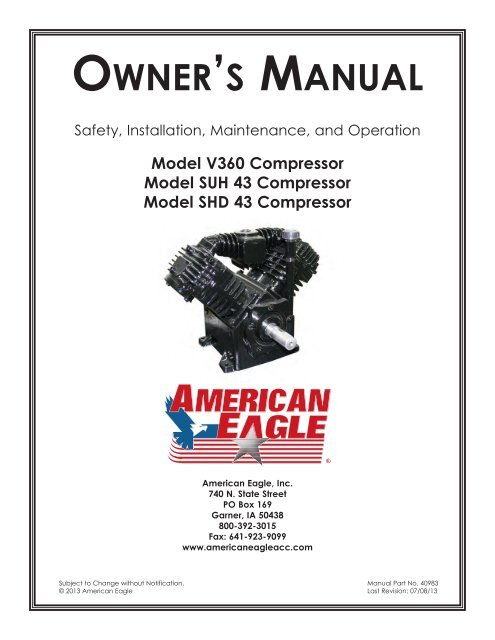
OWNER’S MANUALSafety, Installation, Maintenance, and OperationModel V360 <strong>Compressor</strong>Model SUH 43 <strong>Compressor</strong>Model SHD 43 <strong>Compressor</strong>American Eagle, <strong>Inc</strong>.740 N. State StreetPO Box 169Garner, IA 50438800-392-3015Fax: 641-923-9099www.americaneagleacc.comSubject to Change without Notification.© 2013 American Eagle<strong>Manual</strong> Part No. 40983Last Revision: 07/08/13
<strong>Class</strong> 3 <strong>Compressor</strong> <strong>Manual</strong> RevisionsDate of Revision01/26/10Section RevisedAssemblyDrawingsDescription of RevisionUpdated SHD-43 <strong>Compressor</strong> Assembly to reflectengineering changes.
ii<strong>Class</strong> 3 <strong>Compressor</strong> Owner’s <strong>Manual</strong>IntroductionAmerican Eagle <strong>Compressor</strong>s are designedto provide safe and dependable service fora variety of operations. With proper use andmaintenance, American Eagle <strong>Compressor</strong>swill operate at peak performance for manyyears.This manual contains information vital to thesafe use and efficient operation of this unit.Following the information provided within thismanual can ensure the longevity of thecompressor. Carefully read and study theoperator’s manual before using the unit.Failure to adhere to the instructions couldresult in property damage or even seriousbodily injury to the operator or others closeto the compressor.A copy of this manual is provided with everycompressor and shall remain with thecompressor at all times. Informationcontained within this manual does not coverall maintenance, operating, or repairinstructions pertinent to all possible situations.This manual is not binding.American Eagle reserves the right tochange, at any time, any or all of the items,components, and parts deemed necessaryfor product improvement orcommercial/production purposes. This rightis kept with no requirement or obligation forimmediate mandatory updating of thismanual.This product manual is not intended as atraining manual for beginners or unskilledoperators. This manual offers guidelines forcorrect and safe usage of the compressor,maintenance, and troubleshooting. If moreinformation is required or technicalassistance is needed, please contact AETechnical Support.Some sections of this manual containinformation pertaining to all American Eaglemanufactured compressors and may or maynot apply to your specific model.If this manual becomes damaged,misplaced, or unreadable at any point, or ifyou feel that any part of this manual isunclear or incorrect, please contact AETechnical Support at 800-321-3741 or emailat service@americaneagleacc.comFor Technical Questions, Information, Parts, or Warranty, Call Toll-Free at800-321-3741Hours: Monday - Friday, 8:00 a.m. - 5:00 p.m. CSTOr email at the following addresses:Technical Questions, and InformationOrder PartsWarranty Informationservice@americaneagleacc.comparts@americaneagleacc.comwarranty@americaneagleacc.com
SafetySafety 1This manual contains vital information for the safe use and efficientoperation of this unit. Carefully read the operators manual before startingthe unit. Failure to adhere to the instructions could result in serious bodilyinjury or property damage.Every American Eagle <strong>Compressor</strong> willprovide safe and dependable service ifoperated according to instructions. Readand understand the safety precautionsgiven in this manual and on the decalsattached to the shields. Failure to do so canresult in personal injury or equipmentdamage.Operators and maintenance personnel mustalways comply with the safety precautions.These precautions are given here for yoursafety. Review them carefully beforeoperating the compressor and beforeperforming maintenance or repairs.Supervising personnel should developadditional precautions relating to thespecific work area and local safetyregulations.PrecautionsAlways wear safety equipment such asgoggles, ear plugs and head protection atall times when operating the compressor.Do not inspect or clean the compressorwhile the hydraulic power source isconnected. Accidental engagement of thetool can cause serious injury.Before performing any maintenance on thecompressor, place a warning tag on thehydraulic power source or disconnect thehoses from the compressor motor to preventaccidental startup of the compressor.Always connect hoses to the compressorbefore energizing the hydraulic powersource. Be sure all hose connections aretight, both air and hydraulic.Establish a training program for all operatorsto ensure safe operation.Do not operate the compressor unlessthoroughly trained or under the supervisionof an instructor.Do not operate the compressor if it isdamaged, improperly adjusted or notcompletely or properly assembled.Never operate the compressor with any ofthe guards removed.Do not attempt to adjust or disable thecompressors air pressure relief valve. Thisvalve limits the air pressure to 150 PSI.The surface of the air compressor and theplumbing between the compressor and thecooler may reach temperatures above 150degrees. Touching these surfaces duringoperation can cause burns.The air taken in by the air compressor mustbe free of flammable fumes and vapors.<strong>Compressor</strong> speed should not exceed 1300RPM.Use and operate this air compressor only infull compliance with all pertinent O.S.H.A.requirements and all Federal, State andLocal codes or requirements.
2 <strong>Class</strong> 3 <strong>Compressor</strong> Owner’s <strong>Manual</strong>Specifications• Cast Iron Crankcase Casting<strong>Compressor</strong> System Description• Heavy Ductile Iron Crankshaft• Cast Aluminum Cylinder Head• High Temperature Precision Pistons• Stainless Steel Reed Valves• Heavy Duty Journal Bushings• Micro-honed Connecting Rods• Tapered Roller Bearings• Pressure Lubricated System• Oil Pressure Gauge• Pulsation ManifoldSHD-43 Drive System Description• 11 GPM Hydraulic System• 1650 PSI System Pressure• 2500 PSI Pressure Relief Setting• All Steel Plumbing W/ JIC Fittings• 361 CFM, 12 Volt Cooler Fan• Direct Drive Coupling• 12 VDC Solenoid Control Valve• 165 Sq. In., 300 BTU Cooler• 6061 Aluminum Manifold• Air Pressure Control Valve• Model:• Weight:• Delivery:General SpecificationsV360C70 lbs (SHD-43: 165 lbs)23 CFM @ 100 PSI• Maximum Working Pressure:150 PSI• Dimensions: 26”L x 18.25”W x 18”H• Electrical• Oil Capacity:• Cylinders:• Maximum <strong>Compressor</strong> Speed12 VDC1 QuartFour Cylinder(Single Stage)1300 RPM
OperationOperation 3General Operation NotesEach compressor is bench tested under load at the factory to ensure proper break-in andoperation. While it is not necessary to follow any break-in procedure, the following checksshould be made before putting the unit into service and periodically during use.Before Start-UpCheck the oil level in the compressor with the dipstick on the unit. If oil is needed, useAmerican Eagle synthetic compressor oil (P/N C0087) or an equivalent synthetic oil. Note:There may be oil left in the crankcase from the factory bench test. Overfilling may causethe compressor to back blow oil. Always check the oil level and fill to the designatedmarking on the dipstick before putting the unit into service.Check the air intake filters on each head to make certain that they are clean andunobstructed. Dirty air filters are a possible cause of reduced air output.To use the compressor, start the engine and engage the hydraulic system with thecompressor toggle switch. Through the hydraulic valve manifold, the system will nowfunction automatically. Once engaged, adjust the engine speed control to ensure that thecompressor speed does not exceed 1300 RPM under load.SHD-43 Operation NotesIf adjustment is necessary for cable operated speed controls, loosen the jam nut on thecable end, make the adjustment and retighten the jam nut.For electronic operated speed controls, adjust speed adjustment screw as needed to setRPM.For setting engine RPM through the chassis ECM, contact local chassis dealer.When the air pressure falls below 120 PSI, the 12 volt electric solenoid opens allowinghydraulic oil to flow to the hydraulic drive motor then back to the manifold and throughthe oil cooler assembly. Once the air pressure reaches 150 PSI the solenoid closesshutting off the oil flow to the motor and diverts the oil to the oil cooler.With the compressor engaged, the main cooling system, which consists of an oil cooler,electric fan motor and fan continually runs drawing ambient air through the cooler finsand across the fan assembly discharging heated air past the compressor and out thecover assembly.
4 <strong>Class</strong> 3 <strong>Compressor</strong> Owner’s <strong>Manual</strong>MaintenanceThe following table is a list of routine maintenance items, including service intervals. Serviceintervals are listed as hours, days, or weeks, whichever occurs first. American Eaglerecommends that these service intervals be followed.Service IntervalsMaintenance operation Daily Weekly Monthly HourlyDrain air tanksCheck crankcase oil levelCheck fittings and airlinesCheck hydraulic fluid levelInspect and clean air intake filtersClean and operate safety valvesClean cooling fins on radiatorInspect check valveInspect and clean compressor valves 6Replace hydraulic filter 6Replace air filters 3Tighten all fittings and fasteners 3Check all electrical connections 3Check compressor reed valves 250Inspect and clean air check valve 250CHANGE CRANKCASE OIL (see footnote below)Under normal operating conditions, oil changes are required every 3 months. When operating in adirty environment, change the oil more frequently as your particular operating condition dictates.USE AE SYNTHETIC COMPRESSOR OIL P/N C0087.COMPRESSOR CRANKCASE CAPACITY IS 1 QUART.General preventative maintenance includes maintaining proper fluid level in both systems and thegeneral cleanliness of the equipment. Proper fluids according to the specifications are required.
InstallationInstallation 5<strong>Compressor</strong> InstallationComponent InstallationThis section pertains to the installation of the air compressor, PTO, pump and other relateditems. The instructions are intended as a guide to assist you with particular installation.These instructions will provide only general information.Pulsation Chamber AssemblyTorque Value: 31 FT. LBS.Torque and Procedure ChartProcedure: See Head Installation Procedure SectionHead AssemblyTorque Value: 34 FT. LBS.65Procedure: Assemble head on the cylinder with head boltsstarted only, not tight. Working in the pattern shown, torquethree times, increasing the torque each time as follows:First Torque: 10 FT. LBS.Second Torque: 20 FT. LBS.Third Torque: 34 FT. LBS.After five hours of use re-torque bolts to 34 ft-lbs.21Cylinder Assembly3 4Torque Value: 20 FT. LBS.Procedure: After assembling cylinder over pistons and setting into place, tighten (6) capscrews finger tight. In a criss-cross pattern, tighten bolts evenly so all bolts are hand snug.Again in a criss-cross pattern torque each bolt to 20 Ft-lbs., checking each bolt twice.After five hours of use, re-torque bolts to 20 Ft-lbs.Connecting Rod AssemblyTorque Value: 18 FT. LBS.Procedure: Assemble rod onto the crankshaft taking care to align the machined surfacestogether and tighten cap screws finger tight. Tighten bolts until hand tight and torque to18 Ft-lbs. Check twice the torque reading before final assembly of the cylinders.
6 <strong>Class</strong> 3 <strong>Compressor</strong> Owner’s <strong>Manual</strong>SHD-43 InstallationPump Assembly:The pump assembly may either be installed directlyon the PTO or as an optional method, may bedriven by a driveline from the PTO. Pumpmanufacturers provide specific installationinformation for their products and should beconsulted if questions arise.PTO Assembly:Check with the PTO manufactures representativefor specific instructions regarding your particularmake, model, and year of vehicle. As some trucksmay require modification of the transmission crossmember and the exhaust system, themanufacturer’s instructions should be followed toinsure proper installation of the PTO.<strong>Compressor</strong> Assembly:Prepare the mounting location of the compressorby locating and drilling four (4) holes, 7/16”diameter as per the mounting pattern of the aircompressor base. Using four (4) 3/8” x 1.25 GR-5cap screws, 3/8” flat washers, and 3/8” nyloc nuts,secure the compressor in place. The compressor isair cooled, and must have a clean supply ofcooling air to the fan with minimum restrictions.Adequate space must be provided for propercirculation of air.Electrical Connections:From the air pressure switch there are two (2) wires,red and black, running to the outside of thecompressor housing. Connect the black wire to thevehicle frame or other suitable ground. Mount asingle throw toggle switch in a convenient locationand connect the red wire from the compressor tothis switch. Connect the other switch terminal to afuse holder and then to a 12-volt power supply. Athird wire is required from the air compressor switchwhen connecting the speed control into thesystem. (See drawing below)FANGNDCPRSRSPD CTRLLINEMOTORPRESSURESWITCHHYDRAULICMANIFOLDElectric speed control:An optional electric or electronic speed controlmust be used to maintain proper operating speedof the air compressor. The engine speed control willautomatically increase from idle to preset speedwhen engaged and decrease when disengaged.The electric cable pull speed control AmericanEagle P/N 25740 is used on most gasoline engines.The electronic speed controls are used only on Ford7.3 and 6.0L diesel engines. Proper installationinstructions are provided with each system.Hydraulic System:The hydraulic system consists of the pump, oilreservoir, filters and hoses. Installed on thecompressor is a valve block assembly that controlsthe flow to the hydraulic motor. To this block, a 1/2”high-pressure hose must be attached. This hosecomes from the hydraulic pumps pressure side. A3/4” minimum low-pressure return line is connectedto the oil cooler outlet and is routed to the oilreservoir. American Eagle recommends a sufficientsized reservoir be provided which includes theproper suction and return filters. The cooler on thecompressor is designed and sized to cool the aircompressor efficiently. An auxillary oil cooler isrequired when additional hydraulically operatedequipment are added to the hydraulic system.Pressure on the return line exceeding 200 PSI canand will cause damage to the filter, cooler, andcomponents of the compressor hydraulic system.Return LinePressureLineCBACBACOMPRESSOR (12V INPUT)GROUNDSPEED CONTROL
Pressure Setting InstructionsInstallation 7Kick Out (Step 1)Pressure SettingAdjustmentScrew(145-150 psi)-+Kick On (Step 2)Pressure SettingAdjustmentScrew(115-120 psi)-+Note: Turning adjustment screws clockwiseincreases psi settings. Turning adjustment screwscounterclockwise decreased psi settings.Pressure Setting Instructions:1. Always set the kick out pressure setting first. 145 psi minimum/150 psi maximum.2. After kick out pressure is set, adjust the kick on screw setting at 115 psi minimum/120psi maximum.3. Cycle compressor to verify correct settings.4. For questions about this procedure, please contact <strong>Stellar</strong> Customer Service.
8 <strong>Class</strong> 3 <strong>Compressor</strong> Owner’s <strong>Manual</strong>Assembly DrawingsCrankcase Group (Tapered Shaft)193016372814152627329543273433182811 10113222140122320246363925353138917CRANKCASE GROUPITEM PART DESCRIPTION QTY.1 0485 CAP SCR 0.31-18X1.25 HHGR5 42 5813 CAP SCR 0.31-18X0.75 SH 53 5817 ROLL PIN 0.19X.50 14 5819 GAUGE OIL PSI 1.5 15 5820 OIL PUMP DRIVE SLEEVE V480/V360/200 16 5821 BEARING CARRIER OIL PUMP V360/V480 17 5822 GASKET BEARING CARRIER-V480 (.015) 58 5825 BEARING SEAL V480 19 5826 BEARING CARRIER CLUTCH PLT V480 110 6031 SCREW 0.31-18X1.00 SHC 111 6034 SCREW 0.31-18X1.00 SHC 412 22209 ROLL PIN 0.19X.63 113 22626 PORT PLATE COVER 114 22686 HANDLE DIPSTICK OIL CHECK V480 1ITEM PART DESCRIPTION QTY.15 22839 DIPSTICK (V230/V360) 116 22868 BREATHER CPRSR .50NPT NY8 117 50389 WASHER 0.885X1.115X0.064 COPPER 118 C0041 O'RING-112 119 C0049 CRANKSHAFT V360 TAPER 120 C0050 OIL PUMP 121 C0052 PORT PLATE MACHINED 122 C0054 PORT PLATE COVER GASKET (SMALL) 123 C0055 OIL INTAKE PLUG 124 C0057 O'RING 2-115 FOR OIL PICKUP TUBE 125 C0058 OIL INTAKE FILTER SCREEN 126 C0059 OIL PUMP TRANSFER BUSHING 127 C0060 SPRING OIL PUMP 128 C0062 BREATHER BODY 1ITEM PART DESCRIPTION QTY.29 C0855 BEARING CONE 130 C0856 BEARING CONE LM67048 131 C1163 BEARING CUP (LM67010) 132 C1164 BEARING CUP (L44610) 133 C1174 CRANK CASE V480/360 134 C4703 KEY WOODRUFF 5/32 X 3/4 #8 135 C4841 PLUG 0.38 NPT SQ HD BLK 136 C5416 TUBE OIL INTAKE .38ODX3.00 137 C5929 FTG 8-8 FP-FP CPLR STRAIGHT BLK 138 C6271 FRONT PL GASKET 339 C6273 SNAP RING PISTON PIN N5000-62 140 C6275 PORT PLATE GASKET 1
Crankcase Group (Straight Shaft)Assembly Drawings 918173714153129203716227284830101232254013111221241933636252639353432389CRANKCASE GROUPITEM PART DESCRIPTION QTY.1 0485 CAP SCR 0.31-18X1.25 HHGR5 42 5813 CAP SCR 0.31-18X0.75 SH 53 5817 ROLL PIN 0.19X.50 14 5819 GAUGE OIL PSI 1.5 15 5820 OIL PUMP DRIVE SLEEVE V480/V360/200 16 5821 BEARING CARRIER OIL PUMP V360/V480 17 5822 GASKET BEARING CARRIER-V480 (.015) 58 5825 BEARING SEAL V480 19 5826 BEARING CARRIER CLUTCH PLT V480 110 6031 SCREW 0.31-18X1.00 SHC 111 6034 SCREW 0.31-18X1.00 SHC 412 22209 ROLL PIN 0.19X.63 113 22626 PORT PLATE COVER 114 22686 HANDLE DIPSTICK OIL CHECK V480 1ITEM PART DESCRIPTION QTY.15 22833 CRANKSHAFT V360 S 116 22839 DIPSTICK (V230/V360) 117 22868 BREATHER CPRSR .50NPT NY8 118 23047 KEY FLYWHEEL 1/4 119 50389 WASHER 0.885X1.115X0.064 COPPER 120 C0041 O'RING-112 121 C0050 OIL PUMP 122 C0052 PORT PLATE MACHINED 123 C0054 PORT PLATE COVER GASKET (SMALL) 124 C0055 OIL INTAKE PLUG 125 C0057 O'RING 2-115 FOR OIL PICKUP TUBE 126 C0058 OIL INTAKE FILTER SCREEN 127 C0059 OIL PUMP TRANSFER BUSHING 128 C0060 SPRING OIL PUMP 1ITEM PART DESCRIPTION QTY.29 C0062 BREATHER BODY 130 C0855 BEARING CONE 131 C0856 BEARING CONE LM67048 132 C1163 BEARING CUP (LM67010) 133 C1164 BEARING CUP (L44610) 134 C1174 CRANK CASE V480/360 135 C4841 PLUG 0.38 NPT SQ HD BLK 136 C5416 TUBE OIL INTAKE .38ODX3.00 137 C5929 FTG 8-8 FP-FP CPLR STRAIGHT BLK 138 C6271 FRONT PL GASKET 339 C6273 SNAP RING PISTON PIN N5000-62 140 C6275 PORT PLATE GASKET 1
10 <strong>Class</strong> 3 <strong>Compressor</strong> Owner’s <strong>Manual</strong>Cylinder Group111045616928123712I T E M123456789101112P A R TD E S C R I P T I O NC 0047C Y L I N D E R G A S K E TC 0070R O D C O N N E C T I N G V 360C 2018P I S T O N 2 . 63 O DC 0045C Y L I N D E R V 360C 1569P I S T O N P I NC 627360366037S N A P R I N G P I S T O N P I N N 5000- 62R I N G O I L V 360 F L E X D I V I D E RR I N G C P R S N V 360 S Q G R O O V EC 0065R I N G C P R S N0522W A S H E R 0 . 31 L O C KC 0922C A P S C R 0 . 31- 18X 1 . 00 H H G R 536367CYLINDER GROUPR I N G O I L V 360 R I N G R A I LQ T Y .222124242664
Head GroupAssembly Drawings 1187 6510131112943151421PN 5740ITEM PART DESCRIPTION QTY.1 C0043 GASKET VALVE PLATE 143/230/360 12 24103 VALVE PLATE SUB ASM O/S 13 C0310 GASKET HEAD 143/230/360/480 14 5808 HEAD A/C AL V480 O/S 15 C0291 O'RING-214 VITON 9009-75 16 C0040 WASHER HD BOLT STL 17 5828 WASHER LONG HD BOLT (BRASS) 18 C1582 CAP SCR 0.38-16X3.00 SH HEAD BOLT 29 C1586 CAP SCR 0.38-16X1.75 SH HEAD BOLT 410 C0297 FILTER SCREEN 111 C0296 FILTER FOAM 112 C0294 FILTER RETAINER 113 C0715 FILTER FOAM 114 C0300 SCREW #10-32X0.88 NF 315 23875 WASHER #10 STAR CPRSR 3Manifold DischargeITEM PART DESCRIPTIONQTY.1 6071 MANIFOLD V360 DISCHARGE 12 C1166 0.44 X 1.00 PULSATION TANK BOLT 43 6000 PLUG 0.75 NPT SQ HD CS BLK 14 5797 DRAIN COCK-V480 1
12 <strong>Class</strong> 3 <strong>Compressor</strong> Owner’s <strong>Manual</strong>Head Options#5808Aluminum Air CooledImbedded Filter & 3/4”Threaded NPT Discharge#15195Cast Iron Air Cooled3/4” Threaded Intake Porton Top of Head with3/4” Discharge Port#C1632Aluminum Water Cooled3/4” Threaded Inlet & 3/4”Threaded NPT Discharge#3897Cast Iron Air Cooled3/4” Threaded Inlet & 3/4”Threaded NPT Discharge#22996Cast Iron Air CooledImbedded Filter & 3/4”Threaded NPT Dischargewith Head Unloader Ports#23039Cast Iron Air Cooled3/4” Threaded Inlet & 3/4“Threaded NPT Dischargewith Head Unloader Ports#C1631Aluminum Water CooledImbedded Filter & 3/4”Threaded NPT Discharge
Optional Head UnloaderAssembly Drawings 13PN 23200ITEM PART DESCRIPTION QTY. ITEM PART DESCRIPTION QTY.1 22591 BODY HEAD UNLOADER CPRSR 1 6 0220 CAP SCR 0.25-20 X 1.50 HHGR5 52 22599 GASKET UNLOADER 1 7 22596 CAP SCR 0.38-16X4.00 SH HEAD BOLT 13 22593 PISTON HEAD UNLOADER CPRSR 2 8 C0040 WASHER HD BOLT STL 14 22598 O'RING 2-116 HEAD UNLOADER CPRSR 4 9 22597 SPRING PLUNGER PIN UNLOADER CPRSR 25 22592 COVER HEAD UNLOADER CPRSR 1 10 22594 PIN PLUNGER HEAD UNLOADER CPRSR 2
14 <strong>Class</strong> 3 <strong>Compressor</strong> Owner’s <strong>Manual</strong>Flywheel Options2299712” - B GROOVE2283814” - DUAL GROOVE
Clutch OptionsAssembly Drawings 15C47057” DUAL VC47046” DUAL VC47236” - 8 GROOVESERPENTINE81986” - 8 GROOVE24V SERPENTINE57936” - 8 GROOVE12V SERPENTINEC47757” SINGLE V57746” - 6 GROOVE12V SERPENTINEC4762STRAIGHT BORE
16 <strong>Class</strong> 3 <strong>Compressor</strong> Owner’s <strong>Manual</strong>SUH-43 <strong>Compressor</strong> AssemblyCOMPRESSOR ASSEMBLYITEM PART DESCRIPTIONQTY. ITEM PART DESCRIPTIONQTY.1 C1084 CPRSR V360CWI6NP1 10 C4703 KEY WOODRUFF 5/32 X 3/4 #8 12 C2279 FTG HOSE BARB 0.50 HOSE X 0.50 MNPT 2 11 D1267 FTG .75X90 DEG ST EL BRASS 44164 13 C6235 FTG BRASS ELL 90 DEG A/C 2 12 C4692 FTG 0.75 JIC-ML NPT 12CTX 90 DEG EL 14 25196 HOSE 0.63X12.001 13 C0863 SWITCH PRES COMPRESSOR15 C4665 HOSE CLAMP #8 SS2 14 C5559 FTG ADAPT 1/8ML-1/4FM NPT 1404-2-4 16 23878 NIPPLE 0.75X4.00 SS 304 1 15 C5576 FTG 0.25 HEX NIPPLE 17 D1266 FTG 0.75 ELBOW BRASS 1 16 SEE PAGE 15 FOR CLUTCH OPTIONS8 D1264 FTG 0.75-CLOSE RED BRASS NIPPLE 1 17 D1345 FTG CPRSN 0.12NPT/0.25 TUBE 19 5480 VALVE CHECK 0.75 STANDARD 1 18 25449 TUBE AIR .25X9.00 SUH-43 1
SHD-43 <strong>Compressor</strong> AssemblyAssembly Drawings 17595655299365035373432315740 583049462432542442714153310364744184851174538602039212426285113535452121823119221716ITEM PART DESCRIPTION QTY.1 B0820 BASE WLDMNT SHD 60 12 19644PCBRKT MOTOR MOUNT 19644POWDERCOAT13 14265 CPRSR V360CT66NP 14 C3480 COUPG HYD CPRSR TAPER 15 C4779 COUPG SPIDER SUL 99 BLUE URETHANE 16 C4781 COUPLING LOVEJOY 5/8 17 C6353 WASHER 0.38 FLAT GR8 128 C0944 CAP SCR 0.38-16X1.75 HHGR5 29 0347 NUT 0.38-16 HH NYLOC 610 0523 WASHER 0.38 LOCK 1011 0335 CAP SCR 0.38-16X1.25 HHGR5 812 B0682 BRKT COOLER MOUNT SHD60 113 0351 CAP SCR 0.38-16X1.00 HHGR5 614 C1129 COOLER OIL 115 C6145 FTG 90 DEG 316 C3558 MANIFOLD BLOCK SHD60 117 C6379 FTG SWIVEL NUT ELBOW 12-C6X-S 118 C4766 TUBE ASM 0.75 MANIF TO CLR SHD60 119 C2322 PLUG 1/2 STR THRD 8-P5ON-S 120 0521 WASHER 0.25 LOCK 2ITEM PART DESCRIPTION QTY.21 0483 CAP SCR 0.25-20 X 3.50 HHGR5 222 C4914 VALVE RELIEF CP-200-1-B-0-A-C 123 C4499 VALVE SOLND 124 C4961 PLUG STR HOLLOW HEX 0.38 6-HP5ON 125 C4671 FTG 8-12 C50X JIC 90 DEG 126 C4501 FTG 8 C50X 90 DEG ELL 127 C2297 TUBE ASM 0.50 MANIF TO MOTOR SHD60 128 C4498 FTG ORB/JIC STRT CONNT 12-F5OX-S 129 C4954 TUBE ASM 0.50 MANIF TO MOTOR SHD60 130 8278 FTG ST L 0.75 MNPT/0.125 FNPT SPL 131 4581 NIPPLE 0.75X4.00 BRASS 132 5480 VALVE CHECK 0.75 STANDARD 133 C6150 ST EL ML/FM PIPE 2102-12-12 134 D1345 FTG CPRSN 0.12NPT/0.25 TUBE 135 8276 FTG ML ELBOW 0.25 MNPT/0.125 MNPTSPL 136 C0863 SWITCH PRES COMPRESSOR 137 15046 TBE AIR .25X9.00 138 12180 FILTER MANIFOLD SHD60 CPRSR 139 C4794 NIPPLE O'RING 45 4603-12-12 240 14600 HOSE SUCTION 0.75 X 13.00 241 13638 FTG HOSE BARB 0.75 HOSE X 0.75 90DG 242 13577 CLAMP UNI 1.19 O.D. 5019 443 13529 FILTER AIR SHD60 144 0482 CAP SCR 0.25-20 X 3.00 HHGR5 245 0333 NUT 0.25-20 HHGR5 NYLOC 246 0340 WASHER 0.25 FLAT 447 D1465 WASHER 0.31-0.178 THICK 148 C4570 CAP SCR 0.31-24X0.75 HH NF 149 C0081 CLAMP 0.50 BLK VINYL 150 C5616 CLAMP ROMEX 0.50 151 C6359 FAN 12.00 PULL 12 VOLT 152 5290 WASHER #8 SAE FLAT ZP 653 D0076 NUT #6-32 HH NYLOC 254 D0075 SCREW #6-32X2.75 RH HD MACHINE 255 C4695 HOOD F/G SHD60 156 C0922 CAP SCR 0.31-18X1.00 HHGR5 457 0343 WASHER 0.31 USS FLAT ZINC 458 0342 NUT 0.31-18 HH NYLOC 459 D0993 DECAL SHD43 260 51841 MOTOR HYD SHD60 & SHD43 1.93 CID 1
18 <strong>Class</strong> 3 <strong>Compressor</strong> Owner’s <strong>Manual</strong>Hydraulics/ElectricalSHD-43 Control KitFANGNDCPRSRLINESPD CTRLMOTORPRESSURESWITCHHYDRAULICMANIFOLDCBACBACOMPRESSOR (12V INPUT)GROUNDSPEED CONTROL
PN 30533Multiple ComponentsHydraulics/Electrical 19Typical Hydraulic Circuit for Single Stage Pump withTypical Hydraulic Circuit for Tandum (Two Part) Pump withPN 30532Multiple Components
20 <strong>Class</strong> 3 <strong>Compressor</strong> Owner’s <strong>Manual</strong>Typical Hydraulic Circuit for <strong>Compressor</strong>with Auxiliary CoolerHYDRAULICRESERVOIRFILTER SCREENFILTERAUXILIARYCOOLERSUCTION PORTSINGLEHYDRAULICPUMPCOMPRESSORRETURNPRESSURE
Replacement PartsReplacement Parts 21Overhaul Kit - P/N: 5381Consisting of: Gasket Set (1)Ring Set (1)O-Ring (2)Valve Plate (2)Bearing Oil Seal (1)Oil- 1 QtInner Filter (2)Outer Filter (2)Gasket Set Complete - P/N: C0361Ring Set Complete - P/N: C0069Valve Plate Assembly - P/N: C0314Consisting of: Valve Plate (1)Top Head Gasket (1)Bottom Head Gasket (1)Crankshaft With Bearings:Tapered Shaft - P/N: 23872Straight Shaft - P/N: 23871Canister Filter - P/N: 22867Call 800-321-3741 to Order
22 <strong>Class</strong> 3 <strong>Compressor</strong> Owner’s <strong>Manual</strong>TroubleshootingProblemGeneral TroubleshootingPossible CauseSolution<strong>Compressor</strong> runs hot<strong>Compressor</strong> does not run<strong>Compressor</strong> runs too slow<strong>Compressor</strong> will not stopAir output too low(air pressure okay)<strong>Compressor</strong> cycles(air not being used)Air Output low(Air Pressure Low)Air pressure too lowAir pressure too highHigh crankcase oil usageBlowing oil from crankcasebreatherNo lubricating oil pressureCheck compressor rotation<strong>Compressor</strong> reed valvesDirty intake filterLow oil LevelCheck valve leakingNo 12 Volt Power to <strong>Compressor</strong>Air reservoir fullHydraulic lines not connectedCouplers or hoses blockedAir load against compressorHydraulic pump not workingHydraulic motor not workingCheck valve leaking<strong>Compressor</strong> reed valvesCheck for hose leaksHydraulic flow too lowHydraulic motor wornPower unit relief set too lowHydraulic system too hotSpeed control not workingAir pressure switch set wrongLeaking hoses or fittingsLow compressor speedAir filter dirtyAirlines leakingCheck valve pluggedLeaks in air lineAir pressure switch set wrongDirt in solenoid valveDirty air filterIntake reed valves malfunctionInsufficient torque on head boltsAir pressure switch set wrongAir line leakAir consumption exceeds<strong>Compressor</strong> capacityIntake or exhaust valves damagedPressure switch not operatingInternal contaminationPressure switch not adjustedOil level too highOil leaksPiston rings worn or brokenBlown head gasketPiston rings worn or brokenOil level in crankcase too highHole in pistonAir lock in oil pumpNo oil in crankcasePump suction blockedCheck fittings on hydraulic motorInspect, clean or replace valvesClean filter assemblyLevel Add oil if neededDisassemble, clean, and re-installCheck FuseDrain and activate pressure switchConnect linesLocate and remove restrictionRelieve air pressureCheck flow and pressure settingsInspect and repairDisassemble, clean, and reinstall or replaceInspect, clean or replace valvesTighten any hose fitting leakingCheck and reset flowReplace with new motorReadjust relief valveReservoir too small. Add cooler to system.Check power supply and readjustCheck points and setting on switchTighten all fittings and hosesRefer to compressor too slowClean or Replace FiltersRetighten hosesRemove and clean check valveTighten hoses and fittingsCheck cut-in and cutout settingsRemove and cleanInspect and clean filterIf air back-flows from air filter, reed valve is faulty andneeds to be replaced.Tighten bolts to required torqueReadjust high pressure settingInspect and tighten loose hosesCheck air demand for items using the air supplyInspect and replaceInspect and cleanInspect and cleanReadjust to lower pressureCheck oil level and drain if neededInspect and repair gaskets or sealsReplace ringsReplace gasketReplace ringsCheck oil level and drainReplace pistonLoosen oil gauge while compressor is running. Whenoil begins to flow from fitting, tighten oil gauge.Check oil level and addRemove oil intake plug and inspect intake and screen.Clean blockage.
Troubleshooting 23SHD-43 TroubleshootingIf symptoms of poor performance develop, the following chart can be used as a guide toinvestigate and correct the problem. When diagnosing faults in operations of the aircompressor, always check that the hydraulic power source is supplying the correcthydraulic flow and pressure that is listed in the compressor specification section of thismanual. Note: To Operate, the American Eagle SHD-43 <strong>Compressor</strong> needs 10 GPM and1800 PSI System Pressure.Problem<strong>Compressor</strong> locks up at 110psi and higher while underload:Note: When checkinghydraulic pump flow, makesure the air tank is closedand the compressor isrunning.<strong>Compressor</strong> will notoperate:Possible CauseWeak Hydraulic Motor.Faulty Hydraulic Pump.Oil Pressure is low.Air receiver is full.12 Volt power is not going to the lineside of the pressure switch.Faulty Pressure Switch.Hydraulic Lines not installed correctly.Air Couplers or hoses are blocked.Inline Check-Valve is leaking.Faulty Solenoid Valve.<strong>Compressor</strong> is locked up.Hydraulic motor malfunctioning.Hydraulic pump malfunctioning.SolutionIf the Hydraulic pump is supplying therecommended amount of fluid to the hydraulicmotor, replace the hydraulic motor.If the pump pressure is below the recommendedGPM, replace the Hydraulic pump if necessary.If the oil pressure gauge is reading in the redarea, the oil pressure is low. See the Low OilPressure entry in this troubleshooting section.Drain and activate pressure switch.If there is no power going to the line side of thepressure switch, trace the wire back to thepower source.If there is no power going to the solenoid valve,replace the pressure switch.Reinstall hydraulic lines.Locate and remove restriction.Disassemble, clean, and reinstall or replace.If there is power going to the pressure switch,press down on the solenoid valve bypass button.If the compressor starts to operate, replace thesolenoid valve.Remove the coupler and lovejoy between thecompressor pump and the hydraulic motor. Turnthe compressor over by hand. If the compressorturns over freely, the pump is ok. This indicatesthere is a possible hydraulic problem.Inspect and repair.Check flow and pressure settings.
24 <strong>Class</strong> 3 <strong>Compressor</strong> Owner’s <strong>Manual</strong>Problem<strong>Compressor</strong> runs hot:<strong>Compressor</strong> runs too slow:<strong>Compressor</strong> hesitates orstumbles at restart (115 PSI):Note: <strong>Compressor</strong> kicks outat 150 PSI and kicks backin at 115 PSINo lubricating oil pressure:Possible CauseDirty intake filter.Low oil Level.Inline check-valve leaking.Blown Head or Reed Valve Gasket.Malfunctioning reed valve.Speed control not working.Check for air hose leaks.Hydraulic system too hot.Power unit relief set too low.Hydraulic motor worn.Hydraulic flow too low.Malfunctioning reed valves.Weak Hydraulic Pump.Weak Hydraulic Motor.No oil in crankcase.Pump suction blocked.Air lock in oil pump.Oil pump pin is broken.Malfunctioning oil pump.SolutionClean filter assembly.Add oil if needed.Disassemble, clean, and re-install.Replace Gasket.Inspect, clean or replace valves.Check power supply and readjust.Tighten any hose fitting leaking.Reservoir too small. Add cooler to system.Readjust relief valve.Replace with new motor.Check and reset flow.Inspect, clean, or replace valves.If the hydraulic pump pressure is below therecommended GPM to the hydraulic motor, thehydraulic pump could be weak and needs to bereplaced.If the hydraulic pump is supplying therecommended GPM to the hydraulic motor, thehydraulic motor could be weak and needs to bereplaced.Add oil.Remove oil intake plug and inspect intakescreen. Clean blockage.Loosen oil gauge while the compressor isrunning. When oil begins to flow, tighten thegauge.Replace pin.If the oil pressure gauge indicator is reading inthe red area, use a 1/4” lock washer and point itflat. Remove the oil pump housing cover andplace the lock washer inside the oil pumptransfer bushing so it is between the pump springand the transfer bushing. If oil pressure is still low,add one more lock washer. If two lock washersdon’t increase the oil pressure, replace the oilpump.
Troubleshooting 25ProblemAir Output low:(Air Pressure Low)Air pressure too low:Air pressure too high:High crankcase oil usage:Blowing oil from crankcasebreather:<strong>Compressor</strong> will not stop:Possible CauseDirty air filter.Insufficient torque on head bolts.Intake reed valves malfunction.Air line leaking.Air consumption exceeds <strong>Compressor</strong>capacity.Air pressure switch set incorrectly.Intake or exhaust reed valvesdamaged.Pressure switch not functioningcorrectly.Internal contamination.Pressure switch not adjustedcorrectly.External oil leaks.Oil level too high.Piston rings worn or broken.Oil level in crankcase too high.Blown head gasket.Piston rings worn or broken.Hole in piston.Air pressure switch set incorrectly .Leaking air hoses or fittings.Inspect and clean filter.Tighten bolts to required torque.If air back-flows from air filter, reed valve is faultyand needs to be replaced.Inspect and tighten loose hoses.Check air demand for items using the air supply.Readjust high pressure setting.Inspect and replace.Inspect and clean.Inspect and clean.Readjust to lower pressure.Inspect and repair gaskets or seals.Check oil level and drain if needed.Replace rings.Check oil level and drain.Replace gasket.Replace ring.Replace piston.Check points and setting on switch.Tighten all fittings and hoses.
4-91+)5 )/3- >)99)5;: 796,91;;-5 15:;9)99)5;@ 7-916, :0)33 +6=-9;0- .6336>15/ #>-3=- 465;0 >)99)5;@ 65 7)9;: )5,#>-3=- 465;0 9-7)19 3)*69 1.-;14- >)99)5;@ 65 :31,-: )5, 0)9,>)9-#0- >)99)5;@ 7-916, :0)33 *-/15 .964 ;0- ,);- 9-+69,-, *@ 4-91+)5 )/3- ): ;0- 15:-9=1+- ,);- #01: ,);- >133 *- ,-91=-, .964 ;0- +6473-;-,>)99)5;@ 9-/1:;9);165 +)9, 5 ;0- -=-5; ) >)99)5;@ 9-/1:;9);165 +)9, 1: 56; 9-+-1=-, *@ 4-91+)5 )/3- ;0- .)+;69@ :017 ,);- >133 *- +6479-::69: >133 *- 1::